

Product Description
Mi-Wave’s 955 Series microwave and millimeter-wave E-band RF power amplifiers are engineered to deliver stable gain, reliable output power, and predictable performance at very high frequencies. These amplifiers are designed for laboratory, system integration, and fielded environments where precise RF behavior, thermal stability, and repeatable performance are essential.
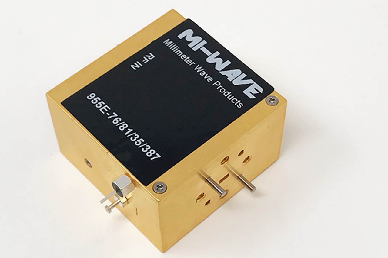
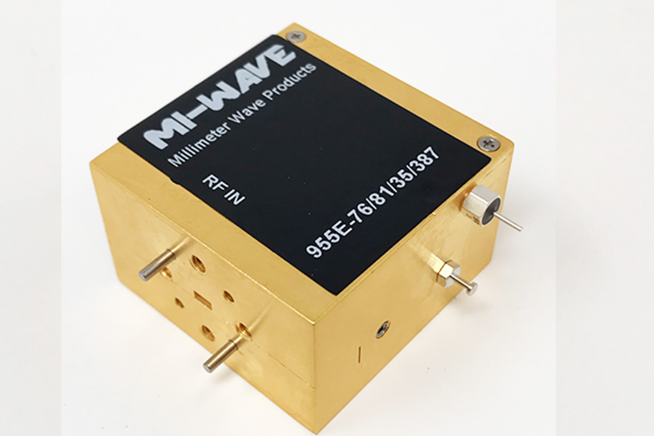
A representative model in the series is the 955E-76/81/35/387 RF Power Amplifier, operating over a 76 GHz to 81 GHz frequency range within the E-band (71–86 GHz). This amplifier provides 30 dB typical small-signal gain, with up to 36 dB gain across the operating band, making it suitable for high-frequency transmit and driver-stage applications in E-band systems.
The amplifier delivers +26 dBm typical output power at P1dB and +28.8 to +29 dBm typical saturated output power (Psat). A typical noise figure of 2.8 dB (3.0 dB over band) is notably low for an E-band power amplifier, supporting improved signal quality in applications where phase noise and spectral cleanliness remain important. A WR-10 waveguide interface enables low-loss interconnection across the E-band frequency range.
Specifications
| Parameter | Specification |
|---|---|
| Model | 955E-76/81/35/387 |
| Configuration | RF Power Amplifier |
| Frequency Range | 76 GHz to 81 GHz |
| Band | E-Band |
| Small Signal Gain | 30 dB typical |
| Output Power (P1dB) | +26 dBm typical |
| Noise Figure | 2.8 dB typical |
| Connector | WR-12 Waveguide, UG-387/U Flange |
| Series | 955 Series |
*Actual product may be different from the image shown per customers specifcations
*All data presented is collected from a sample lot.
* Actual data may vary unit to unit, slightly.
*All testing was performed under +25 °C case temperature.
*Consult factory to confirm if material, plating, size, shape, orientation and any electrical parameter is critical for the application as website information is for reference only.
*Millimeter Wave Products, Inc. reserves the right to change the information presented on website without notice as we continue to enhance the performance and design of our products.
Interested in this Amplifier or other Mi-Wave solutions?
The standard models shown represent only part of Mi-Wave’s broader product capabilities.
Custom configurations are available to support specific frequency bands, interfaces, and application requirements, enabling optimized solutions for specialized RF, microwave, and millimeter-wave systems.
Key Features & Performance Benefits
Wide Frequency Coverage
Supports microwave and millimeter-wave frequency bands with configurations tailored to specific application requirements.
High Output Power Options
Designed to deliver stable output power suitable for transmit chains, signal injection, and system-level testing.
Excellent Linearity
Optimized for low distortion, supporting wideband modulation schemes and multi-carrier operation.
Stable Gain and Gain Flatness
Maintains consistent amplification across the operating band, improving system predictability and calibration.
Clean Spectral Performance
Low spurious output and harmonic control help preserve spectral integrity and meet regulatory requirements.
Flexible Integration
Compatible with RF upconverters, frequency synthesizers, and signal generators for modular system architectures.
Thermally Robust Designs
Engineered for reliable operation under continuous-wave and high-duty-cycle conditions.
Multiple Packaging Options
Available in configurations suitable for laboratory use, rack-mount systems, and embedded RF platforms.
How Amplifiers Work & How to Select the Right RF Amplifier
RF, microwave, and millimeter-wave amplifiers increase the power level of an electrical signal while preserving the signal’s information content and overall integrity. In high-frequency systems, amplifiers are used to overcome transmission losses, improve signal strength, increase communication range, and deliver sufficient RF power to antennas, waveguide systems, and downstream components.
At a basic level, an amplifier takes a low-level RF input signal and uses DC bias power to generate a larger version of that same signal at the output. The amount of amplification is referred to as gain and is typically measured in decibels (dB). Depending on the application, amplifiers may be optimized for low noise, high linearity, wide bandwidth, or high output power.
Amplifiers are commonly used throughout RF signal chains, including receiver front ends, driver stages, transmit systems, radar platforms, satellite communications systems, electronic warfare architectures, and RF test environments. In many systems, the amplifier is one of the most critical active components because its performance directly affects signal quality, range, efficiency, and system reliability.
How Amplifiers Work
An RF amplifier works by using external DC power to increase the amplitude of an incoming RF signal. The input signal controls the behavior of active semiconductor devices within the amplifier, allowing the output signal to contain significantly more RF power than the original input while maintaining the same modulation and information content.
Most RF amplifiers contain multiple amplification stages. Early stages typically focus on gain and signal conditioning, while later stages provide the majority of the output power. Additional matching networks, bias circuits, thermal management structures, and filtering elements help optimize stability, efficiency, bandwidth, and RF performance.
As frequencies increase into microwave and millimeter-wave bands, amplifier design becomes more challenging because small electrical or mechanical variations can affect gain, impedance matching, phase stability, and output power. Careful RF design and precision manufacturing are critical for maintaining stable high-frequency operation.
High power amplifiers are often used near the final stage of the transmit chain, where they provide the RF energy needed to drive antennas, waveguide systems, and long-distance communication links. Low noise amplifiers (LNAs), by comparison, are typically positioned near the receiver front end to amplify weak incoming signals while adding minimal noise.
Key Amplifier Performance Parameters
Several important electrical characteristics determine how an amplifier will perform within an RF or microwave system. These parameters help engineers evaluate whether an amplifier is suitable for a specific frequency band, power level, or application requirement.
Frequency Range: Defines the operating band where the amplifier maintains specified performance. Selecting an amplifier with sufficient bandwidth is critical for maintaining stable gain and output power across the desired frequency range.
Gain: Gain describes how much the amplifier increases the signal level between the input and output. Higher gain can improve signal strength but may also affect system stability and noise performance.
Output Power: Output power determines how much RF energy the amplifier can deliver to a load or antenna. Common specifications include P1dB, saturated output power (Psat), and linear operating power.
Linearity: Linearity measures how accurately the amplifier reproduces the input signal without distortion. This becomes especially important for wideband modulation schemes, radar pulse fidelity, and multi-carrier communication systems.
Noise Figure: Noise figure describes how much additional noise the amplifier introduces into the signal path. Lower noise figure is especially important in receiver and low-level signal applications.
VSWR & Impedance Matching: Proper impedance matching minimizes reflected power and helps maintain amplifier stability and efficiency throughout the RF chain.
Thermal Performance: High-power amplifiers generate heat during operation. Proper cooling and thermal management are critical for maintaining long-term reliability and stable RF performance.
How to Select the Right RF Amplifier
Selecting the correct RF, microwave, or millimeter-wave amplifier involves more than simply choosing the highest gain or output power. The amplifier must properly integrate into the complete RF signal chain while meeting the electrical, thermal, mechanical, and environmental requirements of the application. Careful amplifier selection helps ensure stable system performance, signal integrity, efficiency, and long-term reliability.
Because amplifiers directly affect transmit power, receiver sensitivity, signal quality, and overall link performance, engineers typically evaluate several key parameters together rather than relying on a single specification.
Determine the Operating Frequency Range
The first step in amplifier selection is identifying the required operating frequency range and bandwidth. The amplifier must support the intended RF band while maintaining stable gain, output power, and VSWR performance across the full frequency range.
Operating near the edge of an amplifier’s specified bandwidth may result in degraded gain flatness, reduced output power, or increased reflections. For broadband systems, engineers often select amplifiers with additional frequency margin to maintain consistent performance.
Calculate Required Gain
Gain determines how much the amplifier increases the signal level between the input and output. Proper gain selection requires evaluating the entire RF chain and accounting for all insertion losses and downstream component requirements.
- Cable and waveguide loss
- Filter insertion loss
- Diplexer or OMT loss
- Connector loss
- Antenna gain
- Mixer conversion loss
- Required drive level for downstream stages
Too little gain may prevent the system from reaching required output levels, while excessive gain can create instability, compression, or unwanted distortion.
Evaluate Output Power Requirements
Output power is one of the most important amplifier selection criteria. The required power level depends on the system application, transmission distance, atmospheric loss, antenna gain, and desired Effective Isotropic Radiated Power (EIRP).
- P1dB: The point where gain compresses by 1 dB
- Psat: Maximum saturated output power
- Linear Output Power: Usable output power before significant distortion occurs
- Peak vs Continuous Power: Especially important in pulsed radar systems
Consider Linearity Requirements
Applications using complex modulation schemes or precision radar pulses may require amplifiers operating below saturation to preserve signal fidelity and minimize distortion products.
Review Noise Figure Requirements
For low-level receive systems, noise figure becomes a critical parameter. Low noise amplifiers are often positioned near the antenna or receiver front end to preserve weak incoming signals and improve overall receiver sensitivity.
Check VSWR & Impedance Matching
Proper impedance matching helps minimize reflected power and maintain stable amplifier operation. Poor matching conditions can reduce efficiency, increase standing waves, and potentially damage high-power output stages.
Many high-power systems integrate isolators or circulators to protect amplifiers from reflected energy caused by mismatched loads or antenna reflections.
Evaluate Thermal Management
High-power amplifiers generate substantial heat during operation. Thermal performance directly affects amplifier reliability, efficiency, gain stability, and operational lifetime.
- Passive heat sinks
- Forced-air cooling
- Conduction cooling
- Liquid cooling
- Thermal interface materials
Review Mechanical & RF Interface Requirements
Amplifiers are available with a variety of RF interfaces depending on operating frequency and power level, including coaxial connectors, waveguide flanges, WR-series interfaces, and custom transitions.
Consider Environmental Conditions
Environmental operating conditions such as temperature extremes, vibration, airborne operation, outdoor deployment, and cooling availability should all be considered during amplifier selection.
By carefully evaluating these parameters, engineers can select an amplifier that delivers the required RF performance, efficiency, reliability, and long-term operational stability for microwave and millimeter-wave applications.
Power Amplifier (PA) Calculators
These calculators support PA output level planning, compression headroom (P1dB margin), linearity planning (IIP3/OIP3 and IM3 estimates), EIRP estimates, and quick thermal dissipation approximations for RF, microwave, and millimeter-wave transmit chains.
Jump to: Output Level · P1dB Margin · IIP3 ↔ OIP3 · IM3 Estimate · EIRP · Thermal · dBm ↔ W
1) Output Level Estimator (Pin + Gain − Loss)
Estimate PA output level from input power, small-signal gain, and total losses (attenuators, cables, filters).
2) P1dB Margin (Compression Headroom)
Compute headroom between your estimated output power and the PA 1 dB compression point (P1dB).
3) IIP3 ↔ OIP3 Converter (With Gain)
Convert between input IP3 (IIP3) and output IP3 (OIP3) using gain. Enter any two fields and compute the third.
4) Two-Tone IM3 Estimate (Using OIP3)
Estimate third-order intermodulation (IM3) for a two-tone test. Planning approximation: IM3(dBc) ≈ 2·(OIP3 − Pout_per_tone).
5) EIRP Calculator (Pout + Antenna Gain − Loss)
Compute EIRP from PA output power, antenna gain, and total RF losses (feed, waveguide, radome).
6) Thermal Dissipation Estimate (Pout and Efficiency)
Estimate DC power and heat dissipation from RF output and efficiency. If you have PAE or drain efficiency, enter it as a percent.
7) dBm ↔ Watts Converter
Convert between dBm and Watts for RF power levels. Enter either field and compute the other.
Typical Applications for Microwave & Millimeter-Wave Power Amplifiers
Mi-Wave 955 Series microwave and millimeter-wave power amplifiers are used in a wide range of RF transmit, signal conditioning, and system-integration applications where stable output power, linear amplification, and spectral integrity are required.
Satellite Communication (SatCom)
Power amplifiers are critical in satellite uplink chains to boost RF signals prior to transmission.
Common SatCom applications include:
-
Satellite uplink transmit chains
-
VSAT and gateway terminals
-
Ground station and teleport infrastructure
-
Integration with RF upconverters and BUC architectures
-
High-throughput satellite (HTS) systems
Stable gain and controlled output power support clean uplink spectra and regulatory compliance.
Radar and Sensing Systems
In radar platforms, microwave and mmWave power amplifiers provide the necessary transmit power for signal generation and injection.
Typical radar applications include:
-
Surveillance and tracking radar transmitters
-
FMCW and pulse-Doppler radar systems
-
Ground-based, airborne, and maritime radar platforms
-
Radar signal injection and calibration
High linearity and gain stability improve range performance and target detection accuracy.
Point-to-Point Microwave and Millimeter-Wave Links
Power amplifiers support long-distance and high-capacity wireless links.
Applications include:
-
Microwave and mmWave backhaul links
-
Fixed wireless access (FWA) systems
-
Private and critical infrastructure networks
-
High-throughput point-to-point radio systems
Clean amplification helps maintain link margin and spectral efficiency.
5G and Millimeter-Wave Wireless Development
Microwave and mmWave power amplifiers are widely used in development and validation of next-generation wireless systems.
Applications include:
-
5G FR2 base station and small cell testing
-
mmWave transmitter development
-
Beamforming and MIMO system validation
-
Wireless backhaul and access research
Linear amplification is essential for wideband modulation and EVM performance.
RF Test, Measurement, and Research
In laboratory and production environments, power amplifiers provide controlled RF output levels.
Typical uses include:
-
RF and mmWave test benches
-
Signal source amplification
-
Device and subsystem characterization
-
Automated test equipment (ATE)
Repeatable performance supports accurate testing and validation workflows.
Microwave & Millimeter-Wave Power Amplifier FAQ
These quick answers cover microwave and millimeter-wave RF power amplifiers used in satellite communications (SatCom), radar, point-to-point radio, 5G/mmWave systems, telemetry, electronic warfare, and RF test and measurement applications.
Quick Answers
What does an RF power amplifier do?
An RF power amplifier increases the power level of an RF, microwave, or millimeter-wave signal so it can be efficiently transmitted by an antenna or injected into a system under test. It is typically the final active stage in a transmit signal chain.
How is a power amplifier different from a BUC?
A power amplifier provides RF gain only. A Block Upconverter (BUC) integrates an RF upconverter and a power amplifier into a single unit, combining frequency translation and amplification for satellite uplink applications.
Why is linearity important in microwave power amplifiers?
High linearity minimizes distortion, intermodulation products, and spectral regrowth. This is critical for wideband modulation, multi-carrier signals, low EVM, and regulatory compliance in modern RF systems.
Can power amplifiers be used with RF synthesizers?
Yes. Power amplifiers are commonly paired with RF synthesizers, signal generators, and frequency upconverters to increase output power while maintaining frequency accuracy and spectral purity.
What frequency bands do Mi-Wave power amplifiers cover?
Mi-Wave power amplifiers support a wide range of microwave and millimeter-wave bands, including X-band, Ku-band, Ka-band, Q-band, V-band, and higher frequencies depending on configuration.
More Technical Questions
What determines the required output power of an RF power amplifier?
What is gain flatness and why does it matter?
What is the difference between a driver amplifier and a power amplifier?
Are these power amplifiers suitable for continuous-wave (CW) operation?
How does linearity affect EVM and spectral performance?
Can Mi-Wave provide custom power amplifier designs?
Glossary of RF & Microwave Power Amplifier Terms
Core Power Amplifier Definitions
RF Power Amplifier (PA)
An active RF device that increases the power level of an input signal to drive an antenna, load, or next system stage. RF power amplifiers are used in microwave and millimeter-wave transmit chains for satellite communications, radar, telemetry, wireless infrastructure, and test systems.
Microwave Power Amplifier
A power amplifier designed to operate in microwave frequency bands such as X-, Ku-, Ka-, Q-, V-, and W-band. These amplifiers are optimized for high gain, stability, and controlled output power at high frequencies.
Millimeter-Wave Power Amplifier
A power amplifier operating above 30 GHz, typically used in Ka-band and higher frequency systems. Millimeter-wave amplifiers support applications such as SatCom, radar, 5G/mmWave, and scientific research.
Power, Gain, and Linearity
Small-Signal Gain
The amplification provided by a power amplifier when operating below compression. Specified in dB, small-signal gain defines how much the input signal is increased under linear conditions.
Output Power
The RF power delivered by the amplifier at its output port, typically specified in dBm or watts. Output power requirements are driven by link budgets, antenna gain, and regulatory constraints.
1 dB Compression Point (P1dB)
The output power level at which the amplifier gain decreases by 1 dB from its linear value. P1dB defines the maximum usable linear output power of the amplifier.
Saturated Output Power (Psat)
The maximum output power an amplifier can deliver when driven fully into saturation. Psat is often used in constant-envelope or CW applications where linearity is less critical.
Linearity
The ability of an amplifier to amplify signals without distortion. High linearity reduces spectral regrowth, intermodulation products, and adjacent-channel interference in wideband and multi-carrier systems.
Third-Order Intercept Point (IP3 / OIP3)
A measure of amplifier linearity indicating resistance to third-order intermodulation distortion. Higher IP3 values indicate better performance in multi-tone and wideband applications.
Noise and Spectral Performance
Noise Figure (NF)
A measure of how much noise an amplifier adds to the signal. While more critical in LNAs, noise figure still impacts overall system performance in low-power or sensitive transmit chains.
Harmonics
Unwanted signals generated at integer multiples of the fundamental frequency. Harmonics are minimized through amplifier design and output filtering to maintain spectral compliance.
Spurious Emissions
Unwanted discrete spectral components caused by nonlinear behavior or circuit interactions. Low spurious output is critical for regulatory compliance and interference mitigation.
Bandwidth and Frequency Characteristics
Operating Frequency Range
The frequency span over which the amplifier meets specified performance parameters such as gain, output power, and stability.
Instantaneous Bandwidth
The frequency range the amplifier can support at a given operating point without retuning. Wide instantaneous bandwidth enables broadband and multi-carrier operation.
Gain Flatness
The variation in gain across the operating frequency band. Good gain flatness ensures consistent signal amplitude and simplifies system calibration.
Impedance, Matching, and Interfaces
Input Return Loss (S11)
A measure of impedance matching at the amplifier input. Higher return loss indicates better matching and reduced signal reflection.
Output Return Loss (S22)
A measure of impedance matching at the amplifier output, affecting power transfer and load stability.
VSWR (Voltage Standing Wave Ratio)
A ratio describing impedance mismatch. Lower VSWR values indicate better matching and improved amplifier efficiency and reliability.
Connector Interface
The RF interface used to connect the amplifier, such as SMA, N-type, waveguide flange, or coaxial connectors, depending on frequency and power level.
Power, Control, and Thermal Management
DC Power Supply
The electrical input required to operate the amplifier, commonly specified by voltage and current. Power amplifiers may operate from single-supply or multi-supply rails.
Biasing
The method of setting operating voltages and currents for the amplifier’s active devices. Proper biasing ensures stable gain, linearity, and long-term reliability.
Thermal Management
The removal of heat generated during operation using heatsinks, conduction cooling, or forced air. Effective thermal design is essential for maintaining performance and preventing damage.
Duty Cycle
The percentage of time the amplifier is transmitting at a given power level. Duty cycle affects thermal loading and average power dissipation.
Packaging and Deployment
Module
A compact, self-contained amplifier assembly designed for integration into larger RF systems or subsystems.
Rack-Mount Amplifier
A power amplifier packaged for laboratory, ground station, or data-center environments.
Ruggedized Amplifier
An amplifier designed for harsh environments, including outdoor, airborne, mobile, or defense applications, with extended temperature and mechanical tolerance.
System-Level Considerations
Transmit Chain
The sequence of RF components leading from signal generation through amplification and transmission. Power amplifiers are typically the final active stage before the antenna.
Spectral Compliance
Meeting regulatory limits for emissions, harmonics, and adjacent-channel power. Power amplifier performance directly impacts compliance.
Reliability and MTBF
Long-term operational stability and mean time between failures. Critical for mission-critical and continuous-operation systems.
| MIWV P/N | Description | Low Frequency (GHz) | High Frequency (GHz) | Gain (dB) | Output Power P1dB (dBm) | Output Power Psat (dBm) | Input/Output Port | DC Bias | LINK |
|---|---|---|---|---|---|---|---|---|---|
| 955-0.5/20/40/20/SMAFHF | WideBand Power Amplifier | 0.5 | 20 | 40 | +16.5 | 21.5 | SMA-F | +12V (Max) | |
| 955-1/26/40/30/KF | WideBand Power Amplifier | 1 | 26 | 36 | +26 | +30 | 2.92mmF (K) | +18V (Max) | |
| 955-6/8/60/40/KF | 6-8 GHz High Power Amplifier | 6 | 8 | 60 | +38 | +40 | 2.92mmF (K) | +26V (Max) | |
| 955-18/40/25/24/KF | Crossband Power Amplifier | 18 | 40 | 25 | 20 | 24 | 2.92mm Female (K) | +12V | |
| 955A-24/26/40/45/KFH | Ka-band Power Amplifier | 24 | 26 | 40 | +40 | +45 | 2.92mmF (K) | +24V (Max) | |
| 955A-24/30/40/45/KFH | Ka-band Power Amplifier | 24 | 30 | 40 | 45 | 2.92mm K Female Coaxial Connector | +28V | ||
| 955(34)-25.25/27.5/38/45/595 | WR34 Power Amplifier | 25.25 | 27.5 | 36.5 | +41.5 | +45.0 | WR34 Waveguide / UG-595/U | +30V (Max) | |
| 955A-26/28/35/43/599 | Ka-band Power Amplifier | 26 | 28 | 35 | 43 | WR-28 Waveguide, UG-599/ K Female | +20-25V | ||
| 955-26.5/50/30/20/1.85mmF | 26.5-50 GHz Power Amplifier | 26.5 | 50 | 38 | +25 | +28 | 1.85mmF | +8V (Max) | |
| 955AF-22/27/KFH | Ka-band Power Amplifier | 26.5 | 40 | 22 | 27 | 28 | 2.92mm K Female Coaxial Connector | +12-15V | |
| 955AF-30/18/599H | Ka-band Power Amplifier | 26.5 | 40 | 30 | 18 | WR-28 waveguide, UG-599/U Flange | +8V | ||
| 955AF-30/31/599H | Ka-band Power Amplifier | 26.5 | 40 | 30 | 31 | WR-28 waveguide, UG-599/U Flange | +12-+15V | ||
| 955AF-40/36/599H | Ka-band Power Amplifier | 26.5 | 40 | 40 | 36 | WR-28 waveguide, UG-599/U Flange | +6V | ||
| 955A-27/31/35/43/KF | Ka-band Power Amplifier | 27 | 31 | 35 | +42.5 | 2.92mmF (K) | +24V (Max) | ||
| 955A-28/29/30/36/KFH | Ka-band Power Amplifier | 28 | 29 | 40 | 32 | 36 | WR-28 Waveguide, UG-599/U Flange | +21-24V | |
| 955A-29.3/40/41.5/KF/599HAC | Ka-band Power Amplifier | 29.3 | 40 | 41.5 | WR-28,UG-599/K Female | 100 ~ 120V | |||
| 955A-32/38/38/42.5/599 | Ka-band Power Amplifier | 32 | 38 | 38 | 42.5 | WR-28 waveguide, UG-599/U Flange | +30V | ||
| 955A-33/36.5/38/42.5/599 | Ka-band Power Amplifier | 32 | 36 | 45 | 42.5 | WR-28 waveguide, UG-599/U Flange | +30V | ||
| 955A-33/37/38/40/KFH | Ka-band Power Amplifier | 33 | 37 | 38 | 40 | 2.92mm K Female Coaxial Connector | +30V | ||
| 955BF-30/20/383H | Q-band Power Amplifier | 33 | 50 | 30 | 20 | WR-22 waveguide, UG-383/U Flange | +8V | ||
| 955B-35/48/30/27/383H | Q-band Power Amplifier | 35 | 48 | 30 | 25 | 27 | WR-22 waveguide, UG-383/U Flange | +8V | |
| 955B-35/48/30/27/383H | Q-band Power Amplifier | 35 | 48 | 30 | 25 | 27 | WR-22 Waveguide wiith UG-383/U Flange | +8V | |
| 955A-37/44/40/43/KFH | Ka-band Power Amplifier | 37 | 44 | 40 | 43 | 2.92mm K Female Coaxial Connector | +28V | ||
| 955A-37/44/40/45/KFH | Ka-band Power Amplifier | 37 | 44 | 40 | 45 | 2.92mm K Female Coaxial Connector | +28V | ||
| 955B-37/48.2/30/27/1.85mmFH | Q-band Power Amplifier | 37 | 48.2 | 30 | 27 | 1.85mm Female Coaxial Connector | +6V | ||
| 955B-40/50/35/36/383 | U-band Power Amplifier | 40 | 50 | 39 | +28 | +32 | WR22 Waveguide with UG-383 | 19V (Max) | |
| 955U-44.1/35/33/383 | U-band Power Amplifier | 40 | 48.2 | 35 | 30 | 33 | WR-19 Waveguide, UG-383/U-M Flange | +6V | |
| 955UF-25/29/1.85mmF | U-band Power Amplifier | 40 | 60 | 25 | 29 | 1.85mm Female Coaxial Connector | +8-+12V | ||
| 955UF-35/22/383 | U-band Power Amplifier | 40 | 60 | 35 | 22 | WR-19 Waveguide, UG-383/U-M Flange | +8V | ||
| 955UF-25/30/383 | U-band Power Amplifier | 40 | 60 | 25 | +25 | +30 | WR19 with UG/383-U-M | +8 VDC (Max) | |
| 955U-41/42/25/30/383FS | U-band Power Amplifier | 41 | 42 | 40 | +30 | +33 | 2.4mm Female Coaxial Connector | +12 VDC (Max) | |
| 955B-43/46/30/33/2.4mmFH | Q-band Power Amplifier | 43 | 46 | 30 | 29 | 33 | 2.4mm Female Coaxial Connector | +10V (Max) | |
| 955B-43/46/30/33/2.4mmFH | Q-band Power Amplifier | 43 | 46 | 30 | 33 | 2.4mm Female Coaxial Connector | +8V | ||
| 955U-45.5/51.4/46/36/383 | U-band Power Amplifier | 45.5 | 51.4 | 50 | +30 | +36 | WR-19 Waveguide, UG-383/U-M Flange | +19 VDC (Max) | |
| 955U-46/54/35/36/383 | U-band Power Amplifier | 46 | 54 | 35 | +36 | WR-19 Waveguide, UG-383/U-M Flange | +16 VDC (Max) | ||
| 955U-47/52.4/40/37/383 | U-band Power Amplifier | 47 | 52.4 | 40 | 37 | WR-19 Waveguide, UG-383/U-M Flange | +28V | ||
| 955U-47/52.4/40/40/383 | U-band Power Amplifier | 47 | 52.4 | 40 | 40 | WR-19 Waveguide, UG-383/U-M Flange | +28V | ||
| 955U-47.2/48.2/35/39/383 | U-band Power Amplifier | 47.2 | 48.2 | 35 | 37 | 39 | WR-19 Waveguide, UG-383/U-M Flange | +28V | |
| 955U-47.088/47.09/12/24/383 | U-band Power Amplifier | 47.088 | 47.09 | 12 | +24.5 | +27 | WR-19 Waveguide, UG-383/U-M Flange | +12 VDC (Max) | |
| 955U-49/51/40/45/383H | U-band Power Amplifier | 49 | 51 | 40 | 37 | 45 | WR-19 Waveguide, UG-383/U-M Flange | +28V | |
| 955U-49/51/45/47/383H | U-band Power Amplifier | 49 | 51 | 45 | 43 | 47 | WR-19 Waveguide, UG-383/U-M Flange | +28V | |
| 955U-49/51/45/47/383H | U-band Power Amplifier | 49 | 51 | 45 | 43 | 47 | WR-19 Waveguide, UG-383/U-M Flange | +28V | |
| 955B-50/25/27/2.4mmFH | Q-band Power Amplifier | 49.5 | 50.5 | 25 | 27 | 30 | 2.4mm Female Coaxial Connector | +6V | |
| 955B-50/40/44/383H | Q-band Power Amplifier | 49.5 | 50.5 | 40 | 44 | 47 | WR-22 Waveguide with UG-383/U Flanges | +28V | |
| 955V-50/25/20/2.4mmF | V-band Power Amplifier | 49.5 | 50.5 | 25 | 20 | 23 | 2.4mm Female Coaxial Connector | +6V | |
| 955U-50/66/22/15/383 | U-band Power Amplifier | 50 | 66 | 22 | 15 | WR-19 Waveguide, UG-383/U-M Flange | +8V | ||
| 955U-50/67/20/20/1.85mmF | U-band Power Amplifier | 50 | 67 | 20 | 20 | 1.85mm Female Coaxial Connector | +6V | ||
| 955V-50/68/35/18/385 | V-band Power Amplifier | 50 | 68 | 35 | 18 | WR-15 waveguide, UG-385/U Flange | +6V | ||
| 955V-50/70/28/15/385 | V-band Power Amplifier | 50 | 70 | 28 | 15 | WR-15 waveguide, UG-385/U Flange | +6V | ||
| 955VF-25/25/385H | V-band Power Amplifier | 50 | 75 | 25 | 25 | WR-15 waveguide, UG-385/U Flange | +6V | ||
| 955VF-35/15/385 | V-band Power Amplifier | 50 | 75 | 35 | 15 | WR-15 waveguide, UG-385/U Flange | +6V | ||
| 955VF-40/385 | V-Band Power Amplifier | 50 | 75 | 40 | 9 | 12 | WR-15 waveguide, UG-385/U Flange | +6V | |
| 955V-55/65/30/24/385 | V-band Power Amplifier | 55 | 65 | 30 | 22 | 24 | WR-15 waveguide, UG-385/U Flange | +6V | |
| 955V-57/68/25/26/385 | V-band Power Amplifier | 57 | 68 | 25 | 26 | WR-15 waveguide, UG-385/U Flange | +6V | ||
| 955V-57/70/25/30/385 | V-band Power Amplifier | 57 | 70 | 25 | 30 | WR-15 waveguide, UG-385/U Flange | +8V | ||
| 955V-60/25/31.5/385 | V-band Power Amplifier | 59 | 61 | 25 | 31.5 | WR-15 waveguide, UG-385/U Flange | +6V | ||
| 955V-60/25/31.5/385H | V-band Power Amplifier | 59 | 61 | 25 | +28.0 | 31.5 | WR-15 waveguide, UG-385/U Flange | +18V | |
| 955EF-25/15/387 | E-band Power Amplifier | 60 | 90 | 25 | 15 | WR-12 waveguide, UG-387/U Flange | +8V | ||
| 955EF-25-15-387 | E-band Power Amplifier | 60 | 90 | 30 | 15 | WR-12 waveguide, UG-387/U Flange | +6V -12V MAX | ||
| 955EF-30/15/387 | E-band Power Amplifier | 60 | 90 | 30 | 15 | WR-12 waveguide, UG-387/U Flange | +8V -12V MAX | ||
| 955EF-30/20/387 | E-band Power Amplifier | 60 | 90 | 27 | +21.1 | +22.5 | WR12 with UG-387/U | ;+12V (Max) | |
| 955E-67.5/35/30/387H | E-band Power Amplifier | 64 | 71 | 35 | 27 | 30 | WR-12 waveguide, UG-387/U Flange | +6V | |
| 955E-67.5/35/30/387H | E-band Power Amplifier | 65 | 70 | 35 | 27 | 30 | WR-12 waveguide, UG-387/U Flange | +6V | |
| 955E-70/95/20/16/387 | E-band Power Amplifier | 70 | 95 | 20 | 15 | 16 | WR-12 waveguide, UG-387/U Flange | +6V | |
| 955E-71/76/25/30/387 | E-band Power Amplifier | 71 | 76 | 25 | 30 | WR-12 waveguide, UG-387/U Flange | +6V | ||
| 955E-71/76/30/32.5/387 | E-band Power Amplifier | 71 | 76 | 30 | 30.5 | 32.5 | WR-12 waveguide, UG-387/U Flange | +5V | |
| 955E-71/86/25/33/387 | E-band Power Amplifier | 71 | 86 | 25 | +33 | WR12 with UG-387/U | +2.4V (Max) | ||
| 955WF-35/15/387H | W-band Power Amplifier | 75 | 110 | 35 | 10 | 15 | WR-10 Waveguide, UG-387/U-M Flange | +6V | |
| 955E-76/81/30/29/387 | E-band Power Amplifier | 76 | 81 | 30 | 26 | 29 | WR-12 waveguide, UG-387/U Flange | +12V | |
| 955E-76/81/35/387 | E-band Power Amplifier | 76 | 81 | 35 | +28.1 | +29.1 | WR12 with UG-387/U | +8V (Max) | |
| 955E-81/86/25/30/387 | E-band Power Amplifier | 81 | 86 | 25 | 30 | WR-12 waveguide, UG-387/U Flange | +6V | ||
| 955E-81/86/30/32.5/387 | E-band Power Amplifier | 81 | 86 | 30 | 30.5 | 32.5 | WR-12 waveguide, UG-387/U Flange | +5V | |
| 955E-81/86/35/30/387 | E-band Power Amplifier | 81 | 86 | 35 | 30 | WR-12 waveguide, UG-387/U Flange | +13 - +14V | ||
| 955W-89/97/25/24/387H | W-band Power Amplifier | 89 | 97 | 25 | 24 | 27 | WR-10 Waveguide, UG-387/U-M Flange | +12-+15V | |
| 955W-92/96/20/28/387 | W-band Power Amplifier | 92 | 96 | 20 | 28 | WR-10 Waveguide, UG-387/U-M Flange | +6V | ||
| 955W-92/96/25/30/387 | W-band Power Amplifier | 92 | 96 | 25 | 27.5 | 30 | WR-10 Waveguide, UG-387/U-M Flange | +6V | |
| 955W-94/15/387 | W-band Power Amplifier | 92 | 96 | 12 | 32.5 | WR-10 Waveguide, UG-387/U-M Flange | +6V | ||
| 955W-94/20/32.5/387 | W-band Power Amplifier | 92 | 96 | 20 | 32.5 | WR-10 Waveguide, UG-387/U-M Flange | +6V | ||
| 955W-94/25/27/387 | W-band Power Amplifier | 92 | 96 | 25 | 27 | WR-10 Waveguide, UG-387/U-M Flange | +6V | ||
| 955W-94/30/26/387 | W-band Power Amplifier | 92 | 96 | 30 | 26 | 28 | WR-10 Waveguide, UG-387/U-M Flange | +6V | |
| 955W-94/30/30/387H | W-band Power Amplifier | 92 | 96 | 30 | 30 | WR-10 Waveguide, UG-387/U-M Flange | +6V | ||
| 955W-94/30/37/387 | W-band Power Amplifier | 92 | 96 | 30 | 37 | WR-10 Waveguide, UG-387/U-M Flange | +6V | ||
| 955W-94/35/33/387 | W-band Power Amplifier | 92 | 96 | 35 | 33 | WR-10 Waveguide, UG-387/U-M Flange | +18V | ||
| 955W-94/35/35/387 | W-band Power Amplifier | 92 | 96 | 35 | 35 | WR-10 Waveguide, UG-387/U-M Flange | +13 - +14V | ||
| 955W-93/95/20/30/387 | W-band Power Amplifier | 93 | 95 | 20 | 30 | WR-10 Waveguide, UG-387/U-M Flange | +6-+12V |
Interested in this product or other Mi-Wave solutions?
Contact our team to discuss your frequency range, interface needs, and application requirements.
Custom configurations are available for specialized RF, microwave, and millimeter-wave systems.
Return to High Power Amplifers Page
Return to Amplifiers
Return to Products Page