

Products> Antenna Products > Waveguide Probe Antennas
Product Description
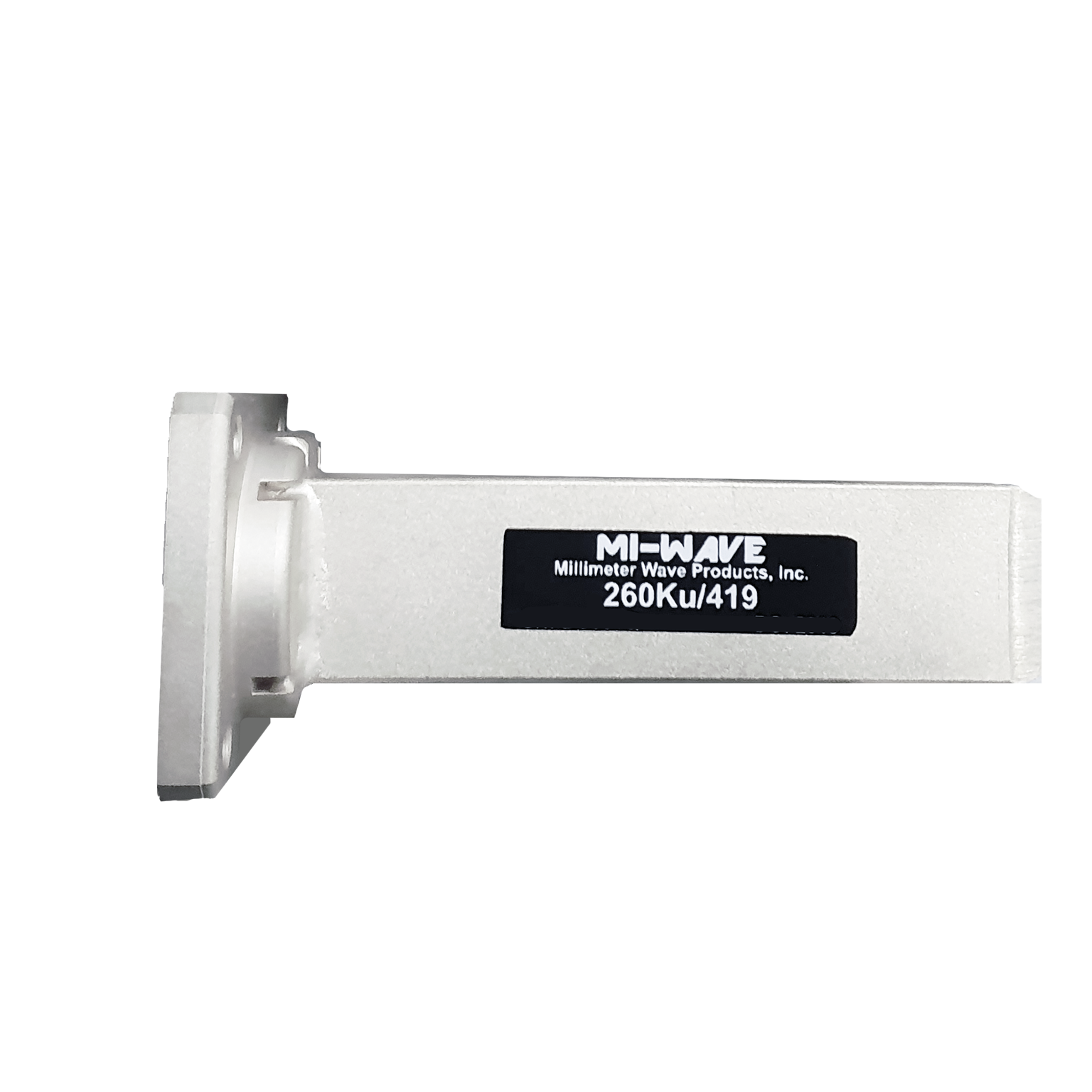
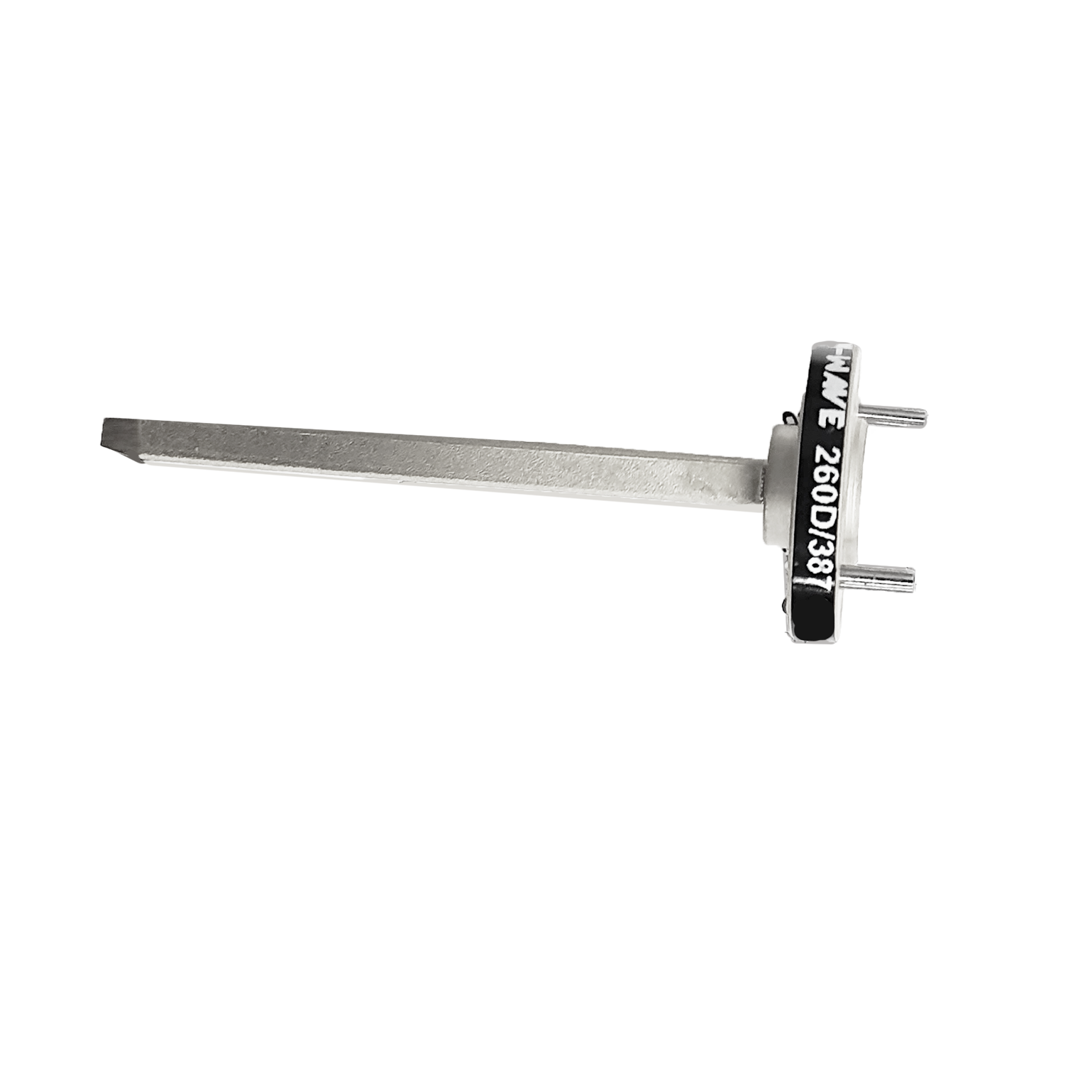
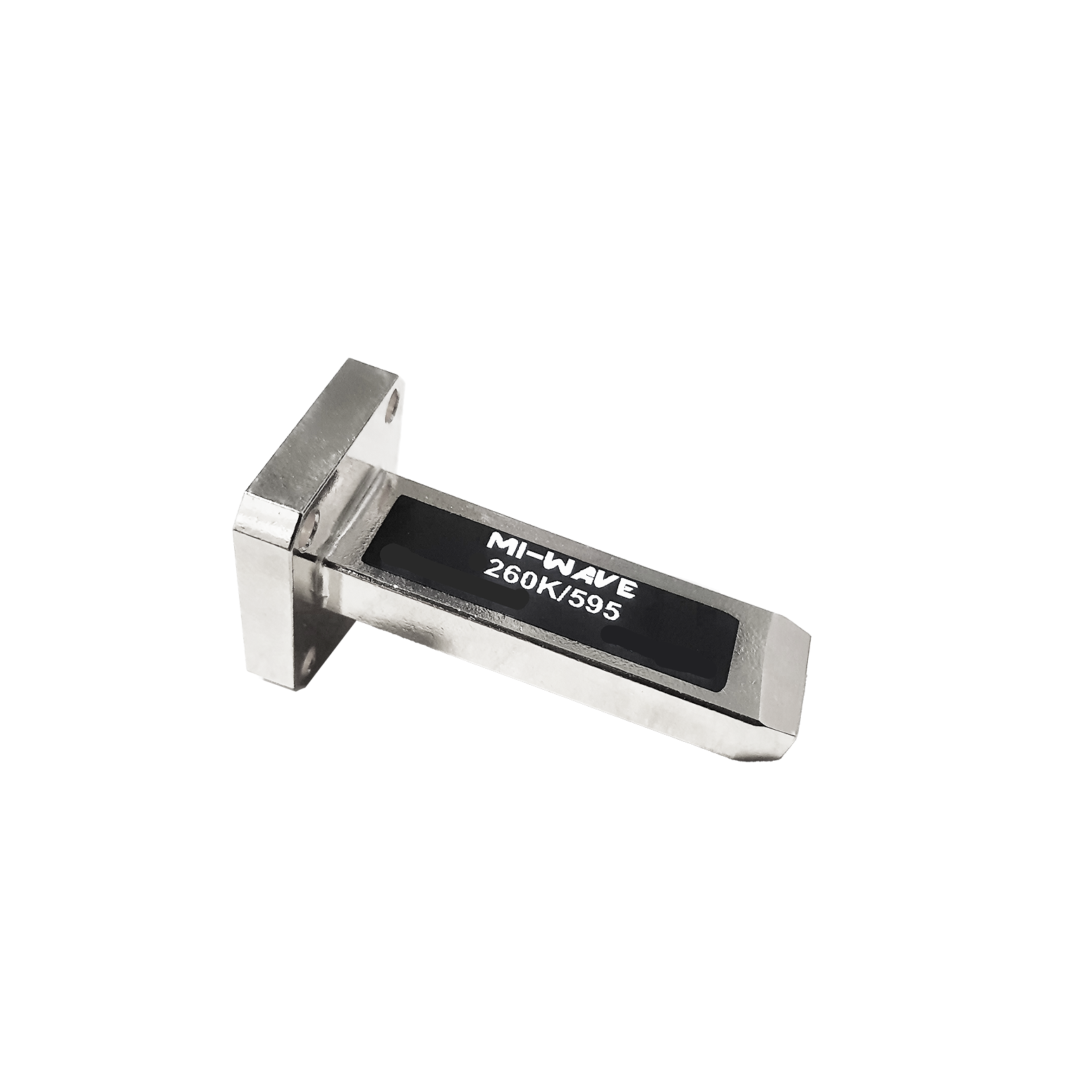
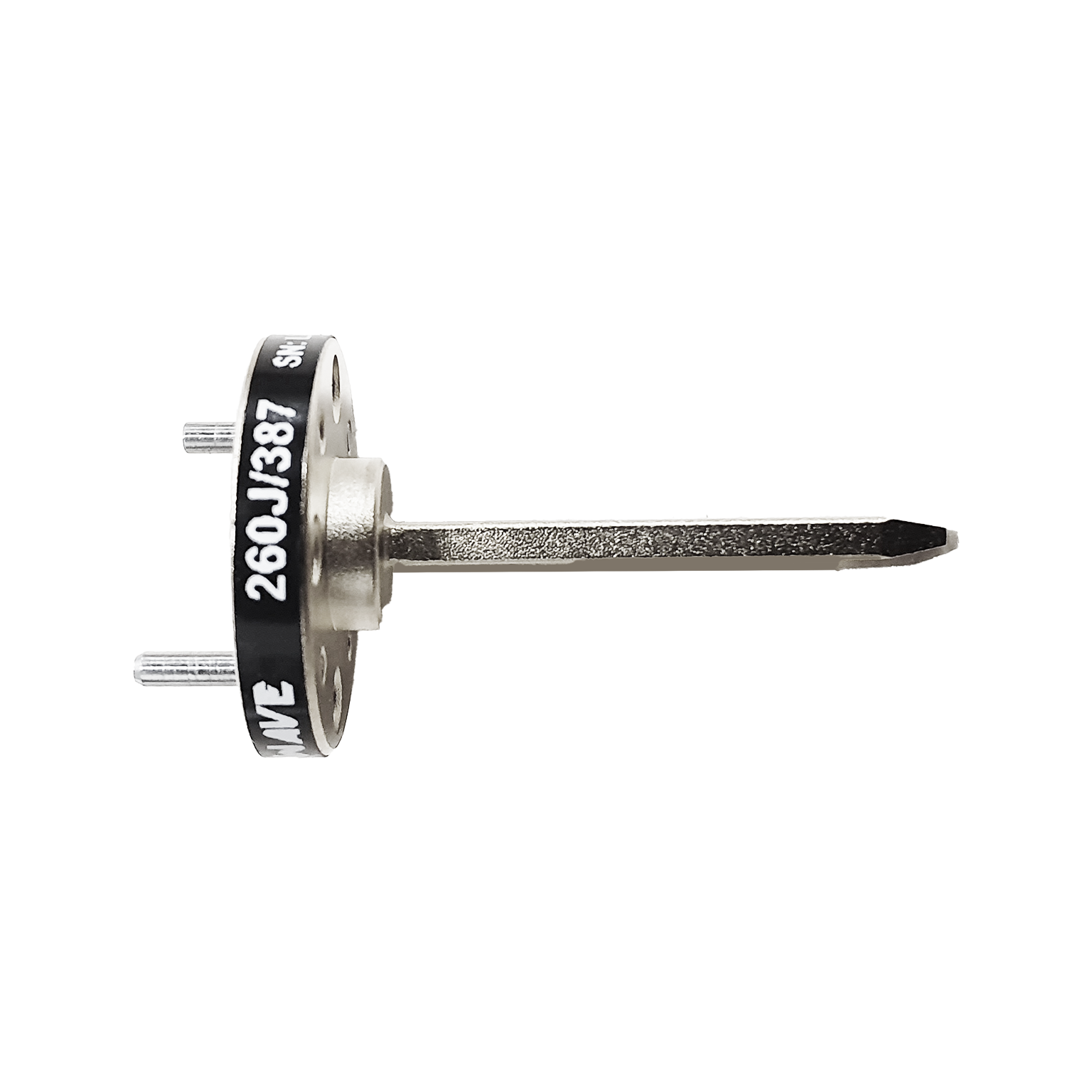
Mi-Wave’s Waveguide Probe Antennas, including the 260 Series, are precision-engineered antennas designed to deliver high directivity, low gain variation, and consistent electrical performance across a broad frequency range from 8.2 GHz to 500 GHz.
These antennas are built for RF, microwave, and millimeter-wave systems that require wideband operation, stable performance, and reliable measurement accuracy. Their design supports demanding environments where repeatable electrical characteristics, low insertion loss, and robust mechanical construction are essential.
Waveguide probe antennas are well suited for testing and measurement, communications systems, radar platforms, and advanced research applications. Available in multiple frequency bands and compatible with standard waveguide flange interfaces, they provide flexible integration into high-frequency RF systems while maintaining strong performance across a wide operating range.
Designed with high power handling and dependable mechanical construction, Mi-Wave’s 260 Series Probe Waveguide Antennas offer a reliable solution for engineers and system designers working in high-frequency applications where precision and durability are critical.
The standard models shown represent only part of Mi-Wave’s broader probe antenna capabilities. Custom configurations are available to support specific frequency bands, interfaces, and application requirements, enabling optimized solutions for specialized RF, microwave, and millimeter-wave systems.

| Model | Band | Low Frequency (GHz) | High Frequency (GHz) | Gain (db) | Length (Inches) | Port | LINK |
|---|---|---|---|---|---|---|---|
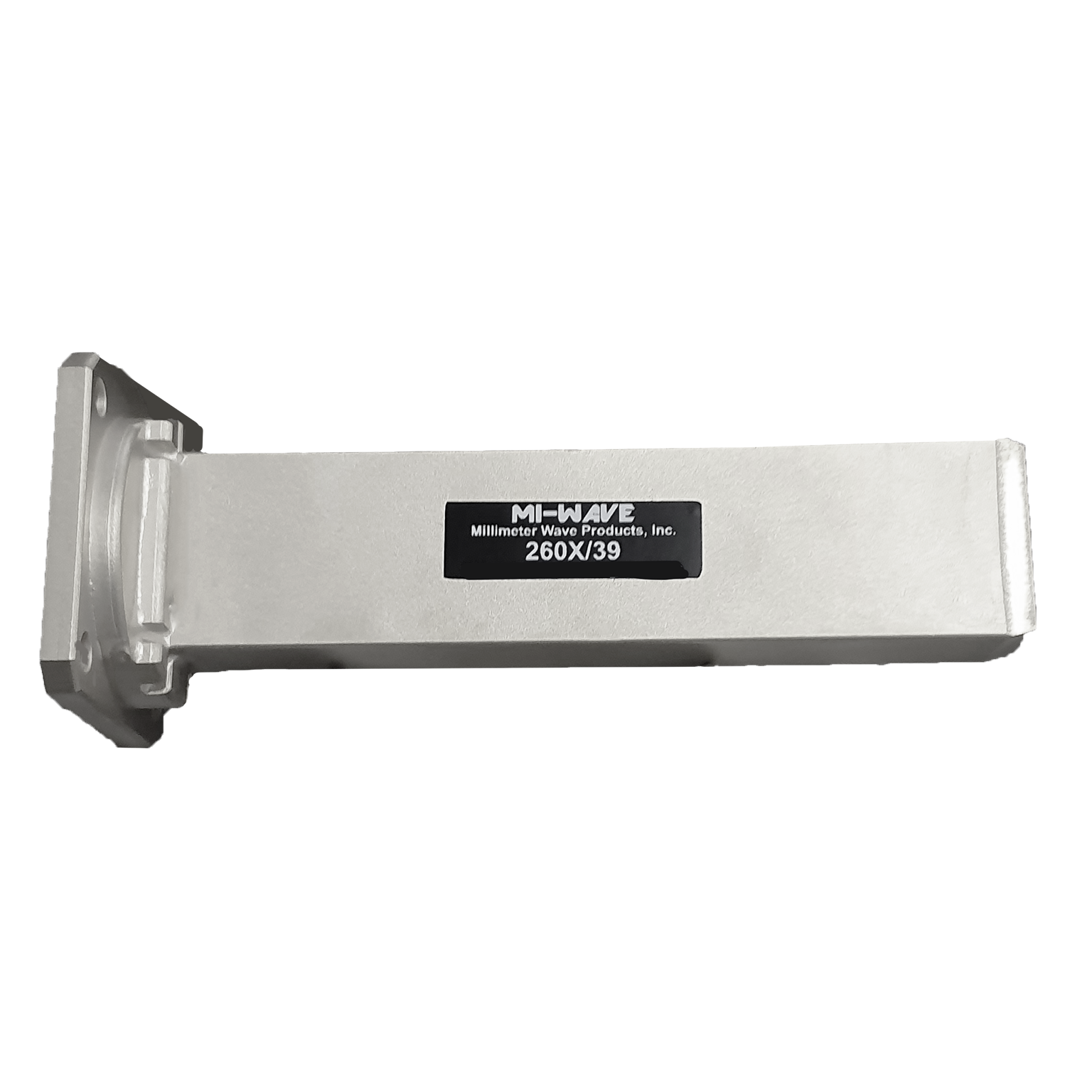
| 260X/39 | X-Band | 8.2 | 12.4 | 5.2 | 4.5 | WR-90 Waveguide Flange UG-39 | |
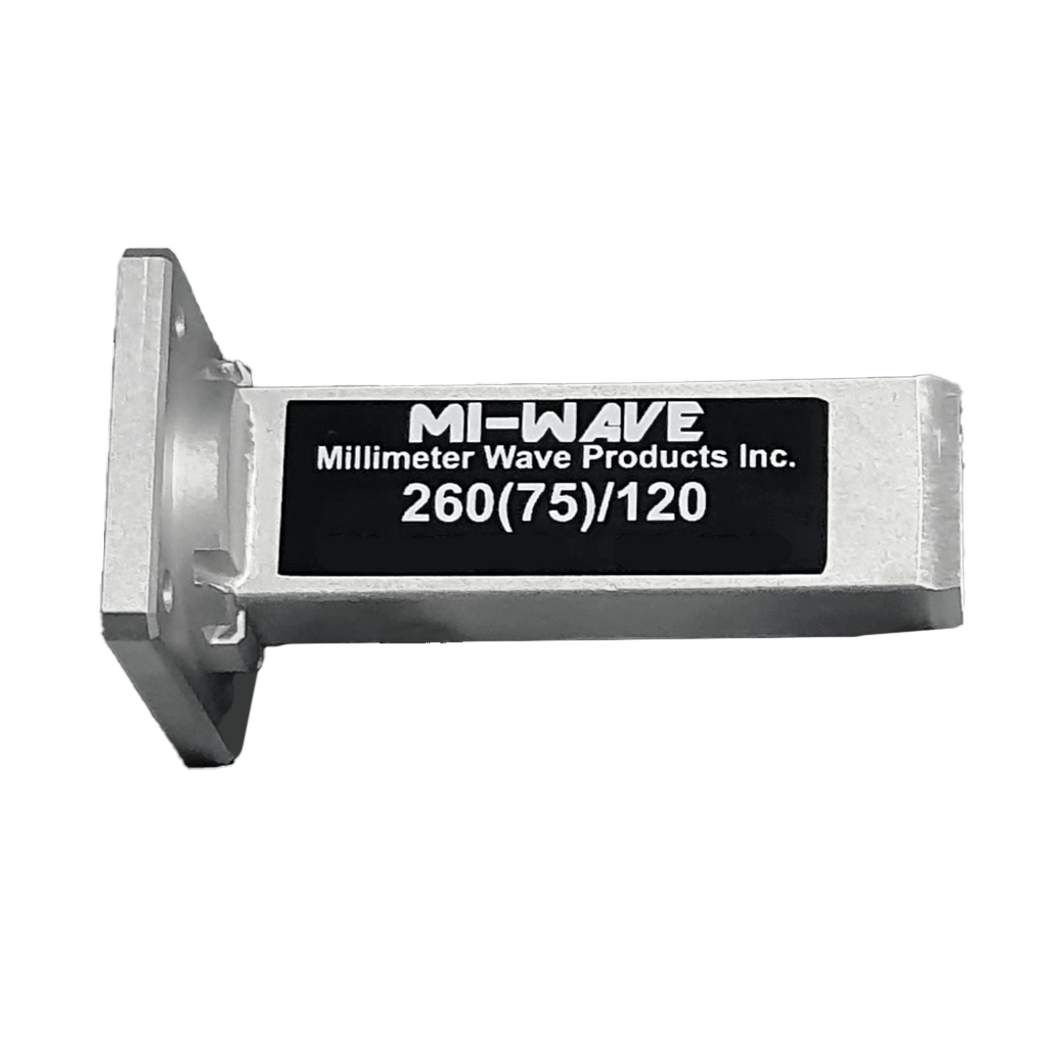
| 260(75)/39 | WR-75 | 10 | 15 | 5.0 | 4 | WR-75 Waveguide Flange UNBR-120/U | |
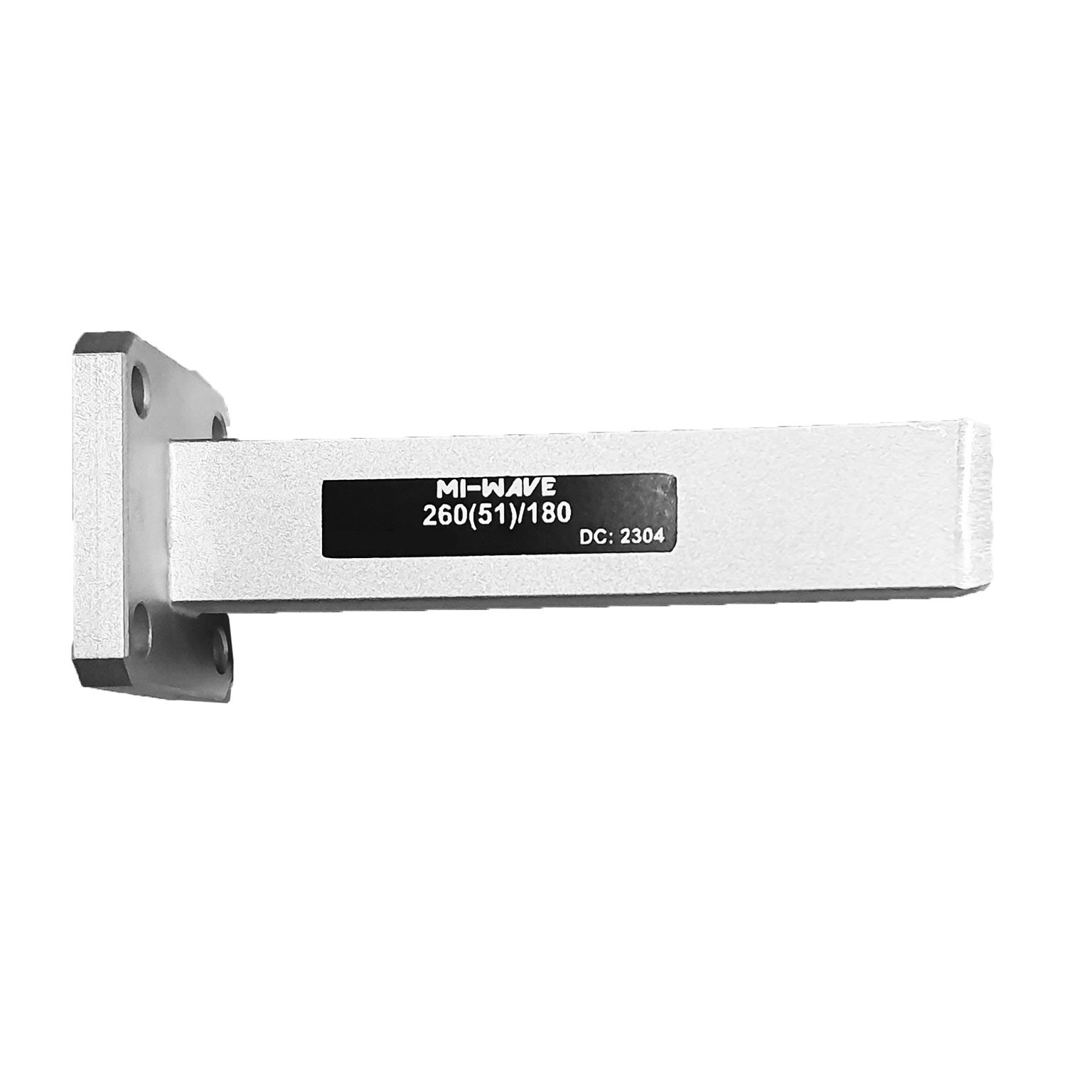
| 260(51)/180 | WR-51 | 15 | 22 | WR-51 Waveguide Flange UBR180 | |||
| 260K/595 | K-Band | 18 | 26.5 | 4.6 | 4.72 | WR-42 Waveguide Flange UG-595/U | |
| 260(34)/595 | WR-34 | 22 | 33 | 5.0 | 4 | WR-34 Waveguide Flange UG-595/U | |
| 260A/599 | Ka-Band | 26.5 | 40 | 4.9 | 2 | WR-28 Waveguide Flange UG-599/U | |
| 260B/383 | Q-Band | 33 | 50 | 4.9 | 2 | WR-22 Waveguide Flange UG-383/U | |
| 260U/383 | U-Band | 40 | 60 | 5 | 2 | WR-19 Waveguide Flange UG-383/U-M | |
| 260V/385 | V-Band | 50 | 75 | 4.9 | 2 | WR-15 Waveguide Flange UG-385/U | |
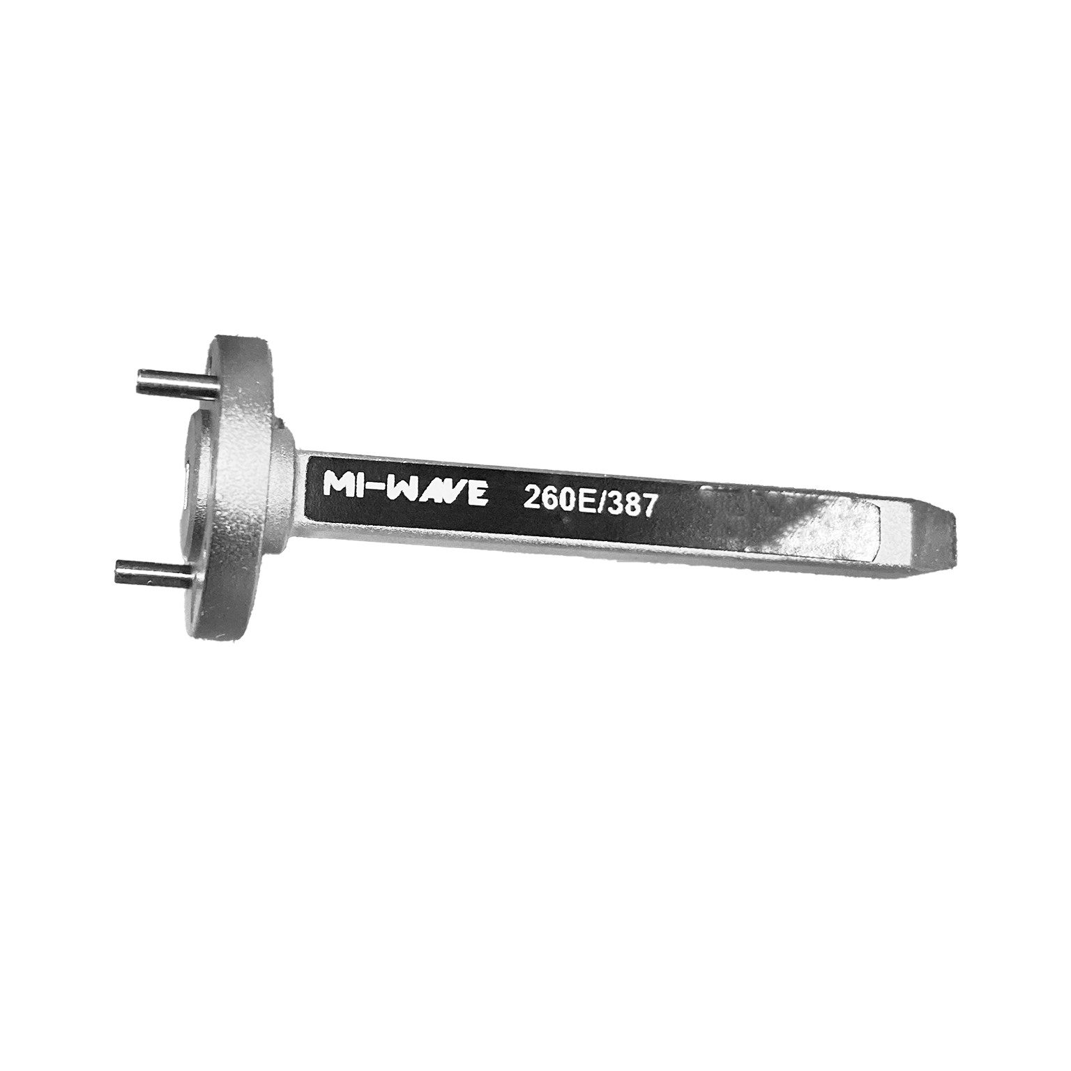
| 260E/387 | E-Band | 60 | 90 | 4.8 | 2 | WR-12 Waveguide Flange UG-387/U | |
| 260W/387 | W-Band | 75 | 110 | 4.8 | 2 | WR-10 Waveguide Flange UG-387/U-M | |
| 260F/387 | F-Band | 90 | 140 | 4.9 | 2 | WR-08 Waveguide Flange UG-387/U-M | |
| 260G/387 | G-Band | 140 | 220 | 4.9 | 1.5 | WR-05 Waveguide Flange UG-387/U-M | |
| 260H/387 | H-Band | 170 | 260 | 4.9 | 1.25 | WR-04 Waveguide Flange UG-387/U-M | |
| 260J/387 | J-Band | 220 | 325 | 4.9 | 1.5 | WR-03 Waveguide Flange UG-387/U-M | |
| 260(2.8)/387 | WR-2.8 | 260 | 400 | 4.9 | WR-2.8 Waveguide Flange UG-387/U-M | ||
| 260(2.2)/387 | WR-2.2 | 325 | 500 | 4.9 | WR-2.2 Waveguide Flange UG-387/U-M |
*All data presented is collected from a sample lot.
* Actual data may vary unit to unit, slightly.
*All testing was performed under +25 °C case temperature.
*Consult factory to confirm if material, plating, size, shape, orientation and any electrical parameter is critical for the application as website information is for reference only.
*Millimeter Wave Products, Inc. reserves the right to change the information presented on website without notice as we continue to enhance the performance and design of our products.
Key Features & Performance Benefits
Extremely Wide Frequency Coverage
Waveguide probe antennas are available across an exceptionally broad frequency range from 8.2 GHz to 500 GHz, making them suitable for RF, microwave, and millimeter-wave systems that span multiple bands and advanced high-frequency applications.
High Directivity Performance
These antennas provide strong directional characteristics that support precise signal transmission and reception in measurement, communication, radar, and research environments.
Low Gain Variation
Waveguide probe antennas are designed to maintain consistent electrical performance across their operating range, helping engineers achieve repeatable results in test, calibration, and system integration applications.
Low Insertion Loss
Efficient waveguide-based construction helps minimize signal loss, supporting improved system performance and more accurate measurement results in high-frequency RF environments.
High Power Handling Capability
These antennas are built to support demanding RF conditions where reliable high-power performance is required, making them suitable for both laboratory and operational system use.
Consistent Electrical Performance
Precision manufacturing and controlled waveguide geometry help ensure stable, repeatable behavior across frequency bands, which is critical in test and measurement systems.
Standard Waveguide Interface Compatibility
Available with standard waveguide flange interfaces, these antennas can be integrated more easily into existing RF, microwave, and millimeter-wave systems.
Robust Mechanical Construction
Waveguide probe antennas are designed for dependable operation in demanding environments, with mechanical durability that supports long-term use in laboratory, production, and field applications.
Ideal for High-Frequency Testing and Measurement
Their combination of wideband performance, low variation, and stable electrical behavior makes them especially useful in applications requiring accurate signal characterization and repeatable measurements.
Custom Configurations Available
Mi-Wave offers custom probe antenna solutions for specific frequency bands, interfaces, mechanical requirements, and specialized applications, providing added flexibility for advanced RF system design.
Applications
Mi-Wave Waveguide Probe Antennas are used in RF, microwave, and millimeter-wave systems that require high directivity, low gain variation, and reliable wideband performance. Their stable electrical characteristics and broad frequency coverage make them well suited for applications involving testing, measurement, communications, radar, and advanced research.
These antennas support engineers and system designers working in environments where repeatability, frequency coverage, and robust performance are critical.
Testing and Measurement
Waveguide probe antennas are widely used in RF and microwave test environments where precise and repeatable electrical performance is essential.
Typical testing and measurement applications include:
- RF system characterization
- Antenna measurement and validation
- Component and subsystem testing
- Calibration setups
- Laboratory signal probing and verification
Their stable performance and low gain variation support more accurate and repeatable results in test environments.
Radar Systems
Waveguide probe antennas are used in radar-related applications where high-frequency performance, directivity, and reliable signal behavior are important.
Common radar applications include:
- Radar subsystem testing
- Radar calibration and verification
- Signal transmission and reception in experimental radar setups
- Millimeter-wave radar research
- High-frequency sensing systems
Their dependable performance makes them useful in both development and validation workflows.
Communications Systems
These antennas are suitable for communication systems operating across microwave and millimeter-wave bands where wideband compatibility and directivity are required.
Typical communications applications include:
- High-frequency RF links
- Microwave and mmWave communication systems
- Signal transmission testing
- Communication subsystem validation
- Experimental wireless systems
Their broad coverage and standard waveguide compatibility support flexible system integration.
RF and Microwave Laboratory Research
Waveguide probe antennas are commonly used in research environments where engineers need broadband frequency coverage and precise signal control.
Typical research applications include:
- Microwave and millimeter-wave experimentation
- RF propagation studies
- Advanced material and component testing
- Academic and government research programs
- Prototype system evaluation
These antennas provide a practical solution for high-frequency development and investigative testing.
Advanced Millimeter-Wave Applications
Because they are available up to 500 GHz, waveguide probe antennas are especially valuable in advanced high-frequency applications.
Common mmWave applications include:
- Submillimeter-wave measurement systems
- Terahertz-adjacent RF research
- High-frequency instrumentation
- Precision probing in advanced labs
- Experimental sensing and detection systems
Their extended frequency coverage supports engineers working at the leading edge of RF and millimeter-wave technology.
Frequently Asked Questions (FAQ)
What is a waveguide probe antenna?
A waveguide probe antenna is a waveguide-based antenna designed to transmit or receive RF energy with high directivity and stable electrical performance across a defined frequency range.
What are the advantages of waveguide probe antennas?
Waveguide probe antennas offer wide frequency coverage, high directivity, low gain variation, low insertion loss, and robust mechanical construction, making them ideal for demanding RF and millimeter-wave applications.
What frequencies do waveguide probe antennas support?
Mi-Wave’s waveguide probe antennas are available from 8.2 GHz to 500 GHz, supporting a broad range of microwave and millimeter-wave applications.
What are waveguide probe antennas used for?
Waveguide probe antennas are commonly used in:
- RF testing and measurement
- Communications systems
- Radar systems
- Microwave and millimeter-wave laboratories
- Advanced research applications
Why are waveguide probe antennas useful in measurement systems?
Their consistent electrical performance, low gain variation, and low insertion loss make them especially useful in measurement systems where repeatability and accuracy are important.
Are waveguide probe antennas suitable for very high frequencies?
Yes. These antennas are designed for operation up to 500 GHz, making them suitable for advanced microwave, millimeter-wave, and other high-frequency research environments.
What determines performance in a waveguide probe antenna?
Performance depends on factors such as frequency band, waveguide size, mechanical precision, insertion loss, directivity, and interface compatibility.
Are these antennas compatible with standard waveguide systems?
Yes. Waveguide probe antennas are available with standard waveguide flange interfaces, making them easier to integrate into existing RF systems.
Can waveguide probe antennas be customized?
Yes. Mi-Wave offers custom configurations for specific frequency bands, interfaces, and application requirements.
Are waveguide probe antennas suitable for radar and communications systems?
Yes. Their combination of directivity, wideband performance, and stable electrical behavior makes them well suited for both radar and communications applications.
What makes waveguide probe antennas reliable in demanding environments?
Their precision engineering, robust construction, and controlled electrical performance help ensure dependable operation in laboratory, production, and advanced RF environments.
RF Wavelength Calculator
Calculate wavelength for probe antenna operation across microwave and mmWave frequencies.
Formula: λ = 0.3 / f(GHz)
Approximate Beamwidth
Estimate beamwidth for probe antennas based on aperture characteristics.
Formula: Beamwidth ≈ 70 λ / D
Approximate Antenna Gain
Estimate gain based on effective aperture size and efficiency.
Formula: G = 10 log10 [ η (πD / λ)² ]
Free Space Path Loss
Estimate signal loss over distance for RF and mmWave systems.
Formula: FSPL = 92.45 + 20log(f) + 20log(d)
Glossary of Waveguide Probe Antenna Terms
This glossary provides detailed definitions of key terms related to waveguide probe antennas used in RF, microwave, and millimeter-wave systems. These antennas are commonly used in testing, measurement, communications, radar, and high-frequency research applications where precision, repeatability, and wideband performance are critical.
Antenna Fundamentals
Waveguide Probe Antenna
A waveguide-based antenna that uses a probe or transition element to radiate or receive electromagnetic energy. These antennas provide controlled directivity, stable performance, and are commonly used in high-frequency measurement and test environments.
Waveguide
A hollow metallic structure designed to guide electromagnetic waves with minimal loss, particularly at microwave and millimeter-wave frequencies.
Probe (RF Probe)
A conductive element inserted into a waveguide or transmission structure to couple RF energy into or out of the system.
Antenna Aperture
The physical opening through which electromagnetic energy is radiated or received. Aperture size directly affects gain and beamwidth.
Radiation Pattern
A graphical representation of how an antenna radiates energy in space, typically showing main lobe and sidelobes.
Main Lobe
The region of the radiation pattern where the majority of energy is concentrated.
Sidelobes
Secondary lobes in the radiation pattern that represent unwanted radiation directions.
Back Lobe
Radiation emitted in the opposite direction of the main beam, often minimized in high-performance antennas.
Electrical Performance Terms
Antenna Gain (dBi)
A measure of how effectively an antenna directs energy compared to an isotropic radiator.
Directivity
The ability of an antenna to focus energy in a specific direction, independent of losses.
Gain Variation
The change in antenna gain across its operating frequency range. Low variation is critical for consistent measurement results.
Insertion Loss
The reduction in signal power as it passes through an RF component or interface.
Return Loss (dB)
A measure of reflected power due to impedance mismatch. Higher return loss indicates better matching.
VSWR (Voltage Standing Wave Ratio)
A ratio that describes impedance matching quality. Lower VSWR indicates better performance.
Impedance Matching
The process of ensuring maximum power transfer between components by minimizing reflections.
Phase Stability
The consistency of signal phase over frequency or time, important in measurement and phased systems.
Group Delay
The variation of signal delay with frequency, affecting signal integrity in wideband systems.
Power Handling
The maximum RF power an antenna can handle without degradation or damage.
Noise Floor
The level of background noise in a system, which can impact measurement sensitivity.
RF and Frequency Terms
Radio Frequency (RF)
Electromagnetic frequencies typically ranging from kHz to hundreds of GHz used for communication and sensing.
Microwave Frequencies
Typically defined as frequencies from 1 GHz to 30 GHz.
Millimeter-Wave (mmWave)
Frequencies from approximately 30 GHz to 300 GHz, where wavelengths are in the millimeter range.
Submillimeter-Wave
Frequencies above 300 GHz, often used in advanced research and specialized sensing applications.
Terahertz (THz)
Frequencies typically above 300 GHz up to several THz, used in cutting-edge imaging and spectroscopy systems.
Frequency Band
A defined range of frequencies allocated for specific applications.
Bandwidth
The range of frequencies over which an antenna or system operates effectively.
Wavelength (λ)
The physical distance between repeating points of a wave, inversely proportional to frequency.
Waveguide and Interface Terms
Waveguide Size (WR Designation)
Standardized dimensions of waveguides (e.g., WR-90, WR-10) corresponding to specific frequency ranges.
Flange Interface
A standardized mechanical connection used to join waveguide components.
UG / CPR / Cover Flanges
Different types of waveguide flange standards used for mechanical and electrical connections.
Mode (TE, TM)
The pattern of electromagnetic field distribution within a waveguide. TE (Transverse Electric) is most common.
Cutoff Frequency
The lowest frequency at which a waveguide mode can propagate.
Single-Mode Operation
Operation where only the dominant mode propagates, ensuring clean signal transmission.
Mode Conversion
Unwanted transformation between modes that can introduce distortion or loss.
Measurement and Test Concepts
Calibration
The process of comparing measurements against known standards to ensure accuracy.
Reference Antenna
A known, calibrated antenna used as a benchmark in measurement systems.
Near-Field Measurement
Testing performed close to the antenna, often requiring mathematical transformation to far-field data.
Far-Field Measurement
Testing performed at a sufficient distance where the radiation pattern is fully developed.
Dynamic Range
The range between the smallest and largest measurable signal levels.
Repeatability
The ability to achieve consistent measurement results under the same conditions.
Measurement Uncertainty
The degree of confidence in a measurement result.
Performance and Efficiency
Aperture Efficiency (η)
The ratio of effective radiating area to physical aperture area.
Effective Aperture (Ae)
The area over which an antenna effectively captures or transmits energy.
Spillover Loss
Energy that does not properly propagate through the intended path, reducing efficiency.
Ohmic Loss
Losses due to resistance in conductive materials.
Surface Roughness Effects
At high frequencies, surface imperfections can increase losses and degrade performance.
Thermal Stability
The ability of an antenna to maintain performance across temperature variations.
Materials and Construction
Conductive Materials
Typically aluminum, copper, or plated metals used to minimize RF loss.
Dielectric Materials
Non-conductive materials that may be used in certain antenna designs or supports.
Surface Finish
The quality of the metal surface, which impacts high-frequency performance.
Mechanical Tolerance
The allowable variation in dimensions during manufacturing.
Precision Machining
High-accuracy fabrication required for millimeter-wave and submillimeter-wave components.
Applications and Systems
Test and Measurement Systems
Systems used to evaluate RF components, antennas, and subsystems.
Radar Systems
Systems that use RF signals for detection, ranging, and tracking.
Communications Systems
Systems that transmit and receive information using RF signals.
EMC Testing
Electromagnetic compatibility testing to ensure systems do not interfere with each other.
Research and Development (R&D)
Experimental and developmental work in laboratories, universities, and government programs.
High-Frequency Instrumentation
Equipment designed for operation at microwave, millimeter-wave, and higher frequencies.
Frequency Bands (Typical)
- X-Band: 8–12 GHz
- Ku-Band: 12–18 GHz
- Ka-Band: 26–40 GHz
- Q-Band: 33–50 GHz
- V-Band: 50–75 GHz
- W-Band: 75–110 GHz
- D-Band: 110–170 GHz
- Submillimeter / THz Range: 170–500 GHz
")
")
")


")
")
")
")
")


Select Your Frequency Band
Click on the frequency band you’re interested in for more specific waveguide probe antennas information.
Choose Mi-Wave for Your High-Frequency Antenna Needs
Mi-Wave’s probe waveguide antennas provide reliable, high-precision solutions for demanding RF and millimeter-wave applications. Our deep expertise, product quality, and custom capabilities make us the go-to partner for engineers and advanced system developers.
Get in touch today to discuss your frequency band, application, or custom design needs.
What This Product Does
Broadband Waveguide Radiation for RF and Millimeter-Wave Systems
Probe waveguide antennas are precision RF components designed to efficiently convert guided electromagnetic energy within a rectangular waveguide into free-space radiation, or to receive radiated signals and couple them back into a waveguide transmission line. This process enables reliable signal transmission and reception across microwave and millimeter-wave frequency bands, supporting high-performance RF systems with minimal loss.
By directly coupling RF energy from the waveguide to an open radiating aperture, probe waveguide antennas provide high radiation efficiency, stable impedance matching, and predictable radiation patterns. This makes them ideal for applications requiring accurate signal characterization, antenna testing, and system validation.
At high frequencies, particularly in microwave, millimeter-wave, and sub-terahertz bands, traditional antenna technologies can experience excessive insertion loss, signal distortion, and reduced power handling. Waveguide probe antennas address these challenges by utilizing a hollow metallic waveguide structure, which supports low-loss signal propagation, improved power handling, and superior electromagnetic performance compared to coaxial or planar antenna designs.
Why Frequency Range Matters
Covering an exceptionally wide frequency range from 8 GHz to 500 GHz, Mi-Wave’s probe waveguide antennas support a broad spectrum of RF and millimeter-wave applications, including:
-
Microwave frequency bands used in radar systems, satellite communications (SatCom), electronic warfare, and wireless communications
-
Millimeter-wave and sub-THz bands critical for 5G and 6G research, high-resolution imaging, spectroscopy, automotive radar, scientific instrumentation, and advanced RF testing
This wideband capability allows engineers and researchers to maintain consistent electrical performance, stable gain, and repeatable measurement results across multiple frequency bands. As a result, system designers can reduce the need for multiple antenna types, streamline test setups, and simplify high-frequency system architectures.
Typical Uses and Applications
Probe waveguide antennas are widely used in RF, microwave, and millimeter-wave test and measurement environments, including:
-
Antenna pattern measurements, gain verification, and near-field and far-field testing
-
RF, microwave, and mmWave system calibration
-
Radar, remote sensing, and target measurement systems
-
High-frequency and broadband wireless communications
-
Development, validation, and verification of transmitters, receivers, and transceiver modules
-
Laboratory research, aerospace testing, and defense applications
These antennas provide accurate signal coupling, reliable transmit and receive performance, and repeatable measurement accuracy across a wide spectrum of operating frequencies.
Key Features and Performance Benefits
-
Ultra-wide frequency coverage from 8.2 GHz to 500 GHz
-
Consistent electrical performance across microwave and millimeter-wave bands
-
Low gain variation for accurate measurements
-
High directivity and excellent power handling
-
Precision waveguide probe design for low loss and high efficiency
-
Multiple standard waveguide flange interface options
-
Custom probe antenna configurations available for specific frequency bands and applications
-
Rugged construction suitable for laboratory, production, and field environments