
Mi-Wave’s 555 Series Bi-Directional Couplers are precision broadband waveguide components designed for accurate sampling and monitoring of both forward and reflected RF energy across microwave and millimeter-wave frequency bands. These couplers are commonly used in RF measurement systems, balanced mixer architectures, signal monitoring applications, and high-frequency subsystem integration where controlled signal sampling and stable broadband performance are required.
The 555 Series uses a broadband broadwall waveguide design to provide reliable coupling performance across standard waveguide bands from 18 GHz to 220 GHz. Coupling values are available in 3 dB, 6 dB, 10 dB, 20 dB, 30 dB, and 40 dB configurations, allowing engineers to select the appropriate sampling level for specific system requirements.
Mi-Wave’s 556 Series utilizes a split-block construction with multi-hole directivity techniques for improved broadband coupling performance and stable RF characteristics.
The 3 dB coupler configurations are especially useful in balanced mixer systems where broadband RF and LO power division is required to feed both sides of a balanced mixer assembly.
The standard models shown represent only part of Mi-Wave’s broader product capabilities. Custom configurations are available to support specific frequency bands, interfaces, and application requirements, enabling optimized solutions for specialized RF, microwave, and millimeter-wave systems.
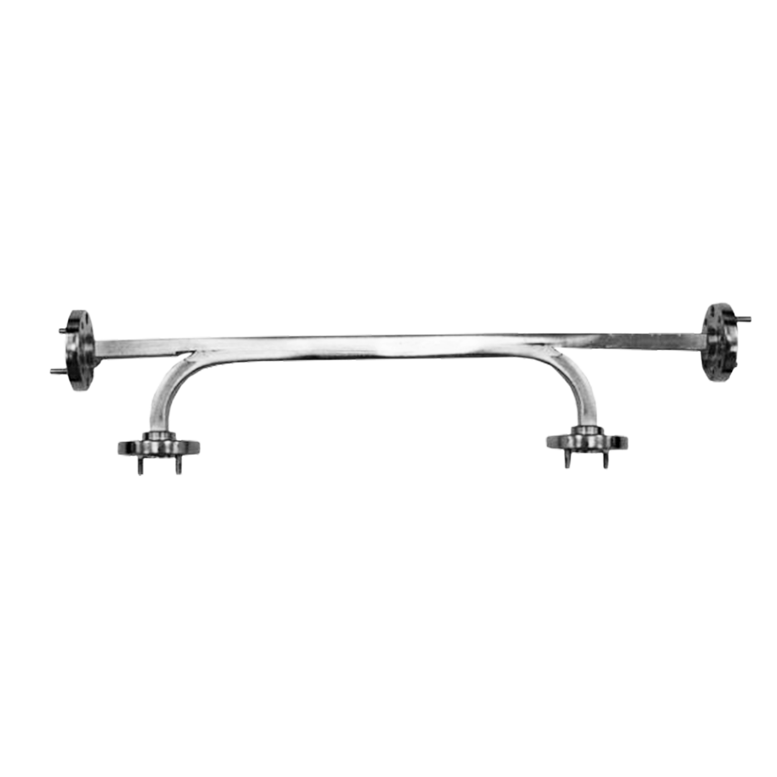
Note: Our website contains just a few types of Couplers we build. Consult with us for your specific needs.
| Model | Band | Frequency Range | Coupling Value | Directivity | Coupling Flatness | Coupling Accuracy | VSWR | RF Ports |
|---|---|---|---|---|---|---|---|---|
| 555A-3/599 | Ka-Band | 26.5–40 GHz | 3 dB | 30 dB | ±0.7 dB | ±1 dB | 1.05:1 | WR-28 Waveguide, UG-599/U Flange |
| 555A-6/599 | Ka-Band | 26.5–40 GHz | 6 dB | 30 dB | ±0.7 dB | ±1 dB | 1.05:1 | WR-28 Waveguide, UG-599/U Flange |
| 555A-10/599 | Ka-Band | 26.5–40 GHz | 10 dB | 30 dB | ±0.7 dB | ±1 dB | 1.05:1 | WR-28 Waveguide, UG-599/U Flange |
| 555A-20/599 | Ka-Band | 26.5–40 GHz | 20 dB | 30 dB | ±0.7 dB | ±1 dB | 1.05:1 | WR-28 Waveguide, UG-599/U Flange |
| 555A-30/599 | Ka-Band | 26.5–40 GHz | 30 dB | 30 dB | ±0.7 dB | ±1 dB | 1.05:1 | WR-28 Waveguide, UG-599/U Flange |
| 555A-40/599 | Ka-Band | 26.5–40 GHz | 40 dB | 30 dB | ±0.7 dB | ±1 dB | 1.05:1 | WR-28 Waveguide, UG-599/U Flange |
| 555B-3/383 | Q-Band | 33–50 GHz | 3 dB | 35 dB | ±1 dB | ±1.5 dB | 1.10:1 | WR-22 Waveguide, UG-383/U Flange |
| 555B-6/383 | Q-Band | 33–50 GHz | 6 dB | 35 dB | ±1 dB | ±1.5 dB | 1.10:1 | WR-22 Waveguide, UG-383/U Flange |
| 555B-10/383 | Q-Band | 33–50 GHz | 10 dB | 35 dB | ±1 dB | ±1.5 dB | 1.10:1 | WR-22 Waveguide, UG-383/U Flange |
| 555B-20/383 | Q-Band | 33–50 GHz | 20 dB | 35 dB | ±1 dB | ±1.5 dB | 1.10:1 | WR-22 Waveguide, UG-383/U Flange |
| 555B-30/383 | Q-Band | 33–50 GHz | 30 dB | 35 dB | ±1 dB | ±1.5 dB | 1.10:1 | WR-22 Waveguide, UG-383/U Flange |
| 555B-40/383 | Q-Band | 33–50 GHz | 40 dB | 35 dB | ±1 dB | ±1.5 dB | 1.10:1 | WR-22 Waveguide, UG-383/U Flange |
| 555U-3/383 | U-Band | 40–60 GHz | 3 dB | 35 dB | ±0.7 dB | ±1 dB | 1.05:1 | WR-19 Waveguide, UG-383/U Flange |
| 555U-6/383 | U-Band | 40–60 GHz | 6 dB | 35 dB | ±0.7 dB | ±1 dB | 1.05:1 | WR-19 Waveguide, UG-383/U Flange |
| 555U-10/383 | U-Band | 40–60 GHz | 10 dB | 35 dB | ±0.7 dB | ±1 dB | 1.05:1 | WR-19 Waveguide, UG-383/U Flange |
| 555U-20/383 | U-Band | 40–60 GHz | 20 dB | 35 dB | ±0.7 dB | ±1 dB | 1.05:1 | WR-19 Waveguide, UG-383/U Flange |
| 555U-30/383 | U-Band | 40–60 GHz | 30 dB | 35 dB | ±0.7 dB | ±1 dB | 1.05:1 | WR-19 Waveguide, UG-383/U Flange |
| 555U-40/383 | U-Band | 40–60 GHz | 40 dB | 35 dB | ±0.7 dB | ±1 dB | 1.05:1 | WR-19 Waveguide, UG-383/U Flange |
| 555V-3/385 | V-Band | 50–75 GHz | 3 dB | 30 dB | ±0.7 dB | ±1 dB | 1.10:1 | WR-15 Waveguide, UG-385/U Flange |
| 555V-6/385 | V-Band | 50–75 GHz | 6 dB | 30 dB | ±0.7 dB | ±1 dB | 1.10:1 | WR-15 Waveguide, UG-385/U Flange |
| 555V-10/385 | V-Band | 50–75 GHz | 10 dB | 30 dB | ±0.7 dB | ±1 dB | 1.10:1 | WR-15 Waveguide, UG-385/U Flange |
| 555V-20/385 | V-Band | 50–75 GHz | 20 dB | 30 dB | ±0.7 dB | ±1 dB | 1.10:1 | WR-15 Waveguide, UG-385/U Flange |
| 555V-30/385 | V-Band | 50–75 GHz | 30 dB | 30 dB | ±0.7 dB | ±1 dB | 1.10:1 | WR-15 Waveguide, UG-385/U Flange |
| 555V-40/385 | V-Band | 50–75 GHz | 40 dB | 30 dB | ±0.7 dB | ±1 dB | 1.10:1 | WR-15 Waveguide, UG-385/U Flange |
| 555E-3/387 | E-Band | 60–90 GHz | 3 dB | 30 dB | ±1 dB | ±1.5 dB | 1.10:1 | WR-12 Waveguide, UG-387/U Flange |
| 555E-6/387 | E-Band | 60–90 GHz | 6 dB | 30 dB | ±1 dB | ±1.5 dB | 1.10:1 | WR-12 Waveguide, UG-387/U Flange |
| 555E-10/387 | E-Band | 60–90 GHz | 10 dB | 30 dB | ±1 dB | ±1.5 dB | 1.10:1 | WR-12 Waveguide, UG-387/U Flange |
| 555E-20/387 | E-Band | 60–90 GHz | 20 dB | 30 dB | ±1 dB | ±1.5 dB | 1.10:1 | WR-12 Waveguide, UG-387/U Flange |
| 555E-30/387 | E-Band | 60–90 GHz | 30 dB | 30 dB | ±1 dB | ±1.5 dB | 1.10:1 | WR-12 Waveguide, UG-387/U Flange |
| 555E-40/387 | E-Band | 60–90 GHz | 40 dB | 30 dB | ±1 dB | ±1.5 dB | 1.10:1 | WR-12 Waveguide, UG-387/U Flange |
| 555W-3/387 | W-Band | 75–110 GHz | 3 dB | 30 dB | ±1 dB | ±1.5 dB | 1.10:1 | WR-10 Waveguide, UG-387/U Flange |
| 555W-6/387 | W-Band | 75–110 GHz | 6 dB | 30 dB | ±1 dB | ±1.5 dB | 1.10:1 | WR-10 Waveguide, UG-387/U Flange |
| 555W-10/387 | W-Band | 75–110 GHz | 10 dB | 30 dB | ±1 dB | ±1.5 dB | 1.10:1 | WR-10 Waveguide, UG-387/U Flange |
| 555W-20/387 | W-Band | 75–110 GHz | 20 dB | 30 dB | ±1 dB | ±1.5 dB | 1.10:1 | WR-10 Waveguide, UG-387/U Flange |
| 555W-30/387 | W-Band | 75–110 GHz | 30 dB | 30 dB | ±1 dB | ±1.5 dB | 1.10:1 | WR-10 Waveguide, UG-387/U Flange |
| 555W-40/387 | W-Band | 75–110 GHz | 40 dB | 30 dB | ±1 dB | ±1.5 dB | 1.10:1 | WR-10 Waveguide, UG-387/U Flange |
Features & Performance Characteristics
Broadband Waveguide Design
The 555 Series is designed for broadband operation across standard waveguide frequency bands from 18 GHz to 220 GHz, supporting microwave and millimeter-wave applications requiring stable coupling performance over wide bandwidths.
Precise Forward & Reflected Power Sampling
Bi-directional couplers simultaneously sample both incident and reflected RF energy, enabling accurate power monitoring, VSWR measurement, and system characterization.
Multiple Coupling Values Available
Coupling configurations include:
- 3 dB
- 6 dB
- 10 dB
- 20 dB
- 30 dB
- 40 dB
This allows engineers to optimize signal sampling levels for measurement, monitoring, or power division applications.
High Directivity Performance
Multi-hole coupling structures help improve directivity and reduce unwanted signal leakage between coupled ports, supporting cleaner RF measurements and improved signal separation.
Full Bandwidth Power Division
The 3 dB coupler versions provide broadband power division for applications such as balanced mixers and LO/RF signal splitting.
Precision Waveguide Construction
Precision machining and waveguide fabrication techniques help minimize discontinuities, reflections, and insertion loss while maintaining stable RF performance.
How Broadband Directional Couplers Work
A broadband directional coupler is a passive RF component designed to sample a controlled portion of electromagnetic energy traveling through a waveguide transmission line while allowing the primary signal to continue along the main signal path.
Mi-Wave’s 559 Series Broadband Directional Couplers use a broadwall multi-hole coupling structure. As RF energy propagates through the main waveguide, precisely designed coupling apertures transfer a predetermined portion of that energy to the coupled port. This provides engineers with a convenient signal sample for measurement, monitoring, calibration, or other RF system functions.
The amount of energy transferred to the coupled port is determined by the specified coupling value. The Series 559 is available in 3, 6, 10, 20, 30, 40, and 50 dB coupling configurations.
For example:
- 3 dB → Couples a relatively large portion of the RF power
- 10–20 dB → Useful for general-purpose signal sampling and monitoring
- 30–50 dB → Provides a much smaller sample for measurement and instrumentation
Higher coupling values correspond to less power being extracted from the main transmission line.
The directional nature of the device allows the coupled port to preferentially sample energy traveling in the intended direction while minimizing unwanted coupling from energy traveling in the opposite direction. This makes the 559 Series useful for RF power monitoring, signal sampling, system characterization, calibration, and test instrumentation.
The coupler may also be used in the reverse function to inject a controlled RF signal into the main transmission line, providing additional flexibility for system testing and calibration.
How to Select the Right Broadband Directional Coupler
Determine the Operating Frequency
Select a directional coupler designed for the required microwave or millimeter-wave frequency range. The corresponding waveguide size must also be compatible with the rest of the RF system.
Choose the Appropriate Coupling Value
The coupling value determines how much RF power is transferred from the main transmission line to the coupled port.
Typical considerations include:
- 3–6 dB → Higher-level coupling or power division applications
- 10–20 dB → General RF monitoring and measurement
- 30–40 dB → Low-level signal sampling
- 50 dB → Very low-level sampling with minimal extraction from the main signal
The exact coupling level should be selected based on the input power and the signal level required by the connected measurement or monitoring equipment.
Evaluate Directivity
Directivity describes how effectively the coupler distinguishes between RF energy traveling in opposite directions. Higher directivity helps reduce unwanted signal contributions at the coupled port and improves measurement accuracy.
Consider Main-Line Insertion Loss
Because the coupler is installed directly in the RF transmission path, main-line insertion loss should be considered when evaluating overall system performance. Lower insertion loss helps preserve available RF power.
Verify Waveguide & Flange Compatibility
The coupler’s waveguide size and flange interface should match the adjoining waveguide components to minimize discontinuities and simplify mechanical integration.
Consider Power Handling
Verify that the coupler can safely accommodate the expected RF power traveling through the main waveguide. This is particularly important in transmitter, radar, amplifier, and other high-power RF systems.
Determine Whether Signal Injection Is Required
If the application requires introducing a calibration or test signal into an existing RF path, the Series 559 can provide a convenient means of coupling the desired signal into the transmission line.
Consider Custom Requirements
For specialized applications, Mi-Wave can provide custom configurations based on frequency range, coupling value, waveguide size, flange interface, and mechanical requirements.
Applications
Power Monitoring & Measurement
Bi-directional couplers are widely used to sample forward and reflected power in RF systems for power monitoring, calibration, and performance verification.
VSWR & Return Loss Measurement
Because the coupler samples both incident and reflected signals, it can be used to evaluate impedance matching, reflected power levels, and overall transmission line performance.
Balanced Mixer Systems
3 dB couplers are commonly integrated into balanced mixer architectures where broadband RF and LO power division is required.
Radar & Electronic Warfare Systems
Couplers support signal routing, monitoring, calibration, and subsystem integration in advanced radar and EW platforms.
RF & Microwave Test Systems
Used in laboratory environments for:
- Signal monitoring
- Network analysis
- Component characterization
- Automated RF testing
Satellite & Communication Systems
Bi-directional couplers are used in communication links where monitoring forward and reflected RF power is necessary for maintaining link stability and system efficiency.
Frequently Asked Questions (FAQ)
What is a bi-directional coupler?
A bi-directional coupler is a passive RF component used to sample both forward and reflected RF energy traveling through a transmission line.
What coupling values are available?
Mi-Wave 555 Series couplers are available in:
- 3 dB
- 6 dB
- 10 dB
- 20 dB
- 30 dB
- 40 dB
What frequency range is supported?
The 555 Series supports standard waveguide bands from 18 GHz to 220 GHz.
What is directivity?
Directivity describes how effectively the coupler separates forward and reflected signals. Higher directivity improves measurement accuracy.
Why are 3 dB couplers important?
3 dB couplers divide RF power approximately equally and are commonly used in balanced mixer and signal splitting applications.
What are bi-directional couplers used for?
Applications include:
- Power monitoring
- VSWR measurement
- Balanced mixers
- Radar systems
- RF testing
- Signal sampling
- Communication systems
Coupler Calculators
Estimate coupled power, return loss, VSWR, reflected power, insertion loss impact, coupling value, and basic RF power conversions for directional and waveguide coupler applications.
Coupled Power
Estimate the RF power available at the coupled port based on main-line input power and the specified coupling value.
Return Loss
Convert reflection coefficient into return loss and estimate how much RF power is being reflected by an impedance mismatch.
VSWR Calculator
Calculate Voltage Standing Wave Ratio from reflection coefficient to evaluate impedance matching within an RF transmission system.
Reflected Power
Estimate the amount of forward RF power reflected back toward the source due to an impedance mismatch.
Insertion Loss Impact
Determine how much RF power remains after a coupler or other passive component introduces a known amount of insertion loss.
Coupling Value
Determine the coupler’s effective coupling value from measured main-line power and coupled-port power.
dBm ↔ Watts Converter
Convert between logarithmic dBm values and linear watts or milliwatts for RF power calculations and measurement comparisons.
Glossary of Bi-Directional Coupler Terms
Bi-Directional Coupler
A passive RF component that samples both forward and reflected electromagnetic energy.
Coupling Value
The amount of RF power extracted from the main transmission line into the coupled port.
Directivity
A measure of how effectively forward and reflected signals are isolated from one another.
Incident Power
The forward RF energy traveling toward the load.
Reflected Power
RF energy reflected back toward the source due to impedance mismatch.
VSWR
Voltage Standing Wave Ratio, a measure of reflected power and impedance matching.
Return Loss
The amount of reflected energy expressed in decibels.
Balanced Mixer
A mixer architecture using balanced signal paths for improved isolation and harmonic suppression.
Insertion Loss
Signal loss introduced into the main transmission path by the coupler.
Broadwall Coupler
A waveguide coupler design where coupling occurs through apertures in the broad wall of the waveguide.
Multi-Hole Coupling
A coupling technique using multiple apertures to improve broadband performance and directivity.
Waveguide Coupler
A coupler specifically designed for microwave and millimeter-wave waveguide systems.
Interested in this product or other Mi-Wave solutions?
Contact our team to discuss your frequency range, interface needs, and application requirements.
Custom configurations are available for specialized RF, microwave, and millimeter-wave systems.
Return to Waveguide Couplers
Return to Products Page
