

Products> Antenna Products > Horn Lens Antennas
Product Description
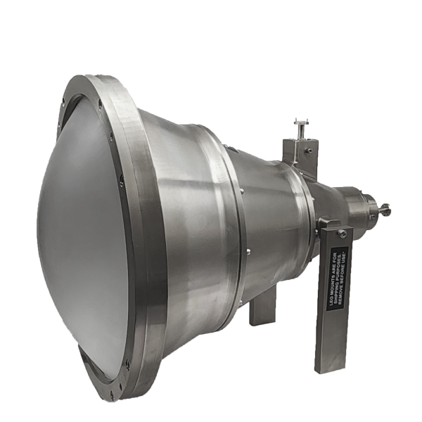
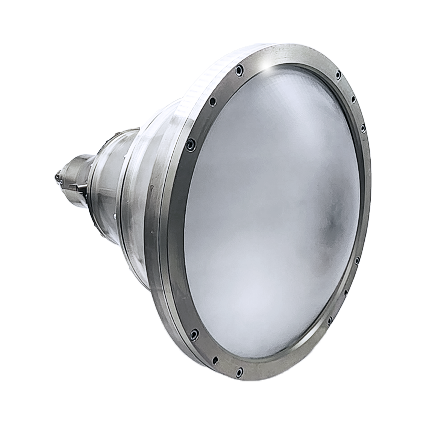
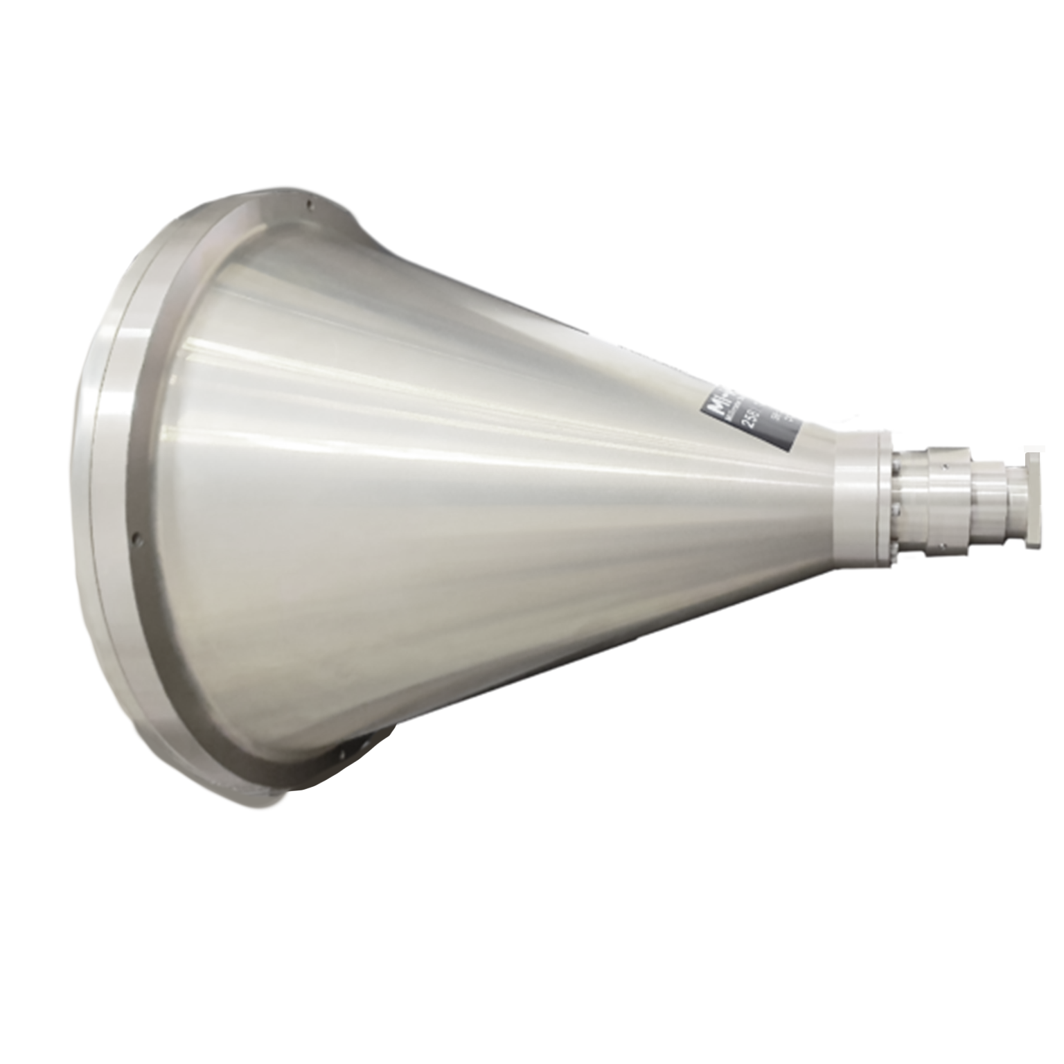
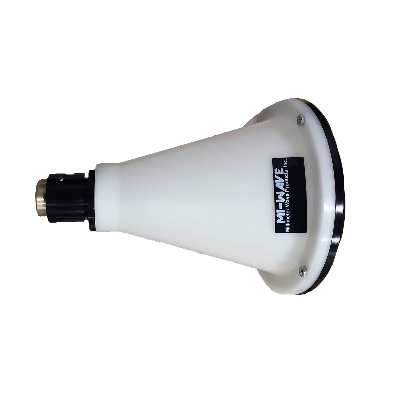
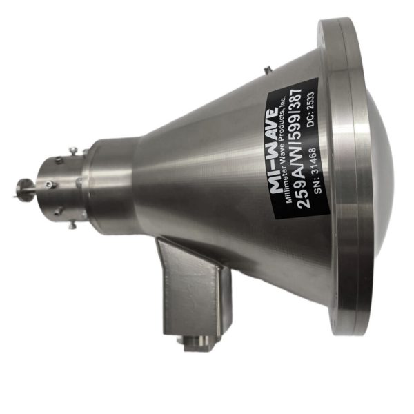
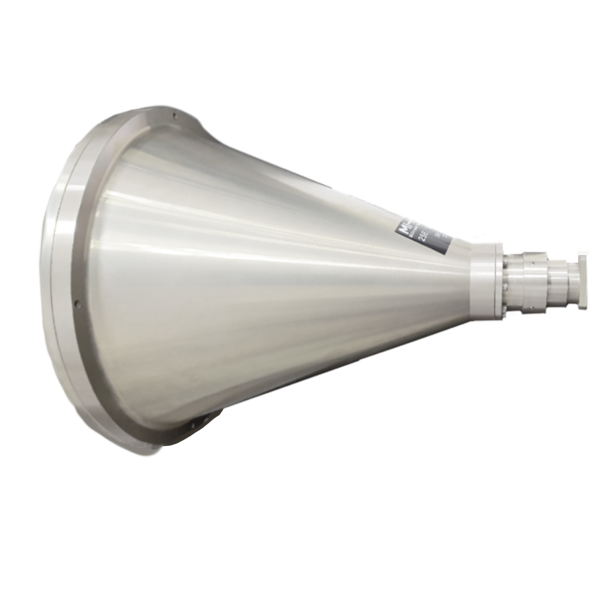
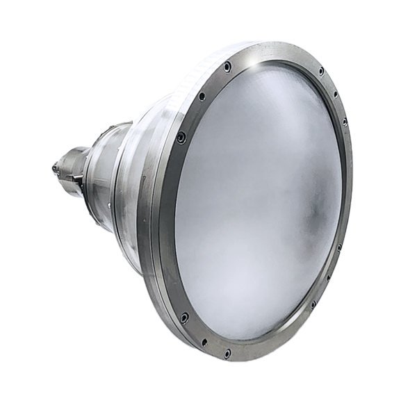
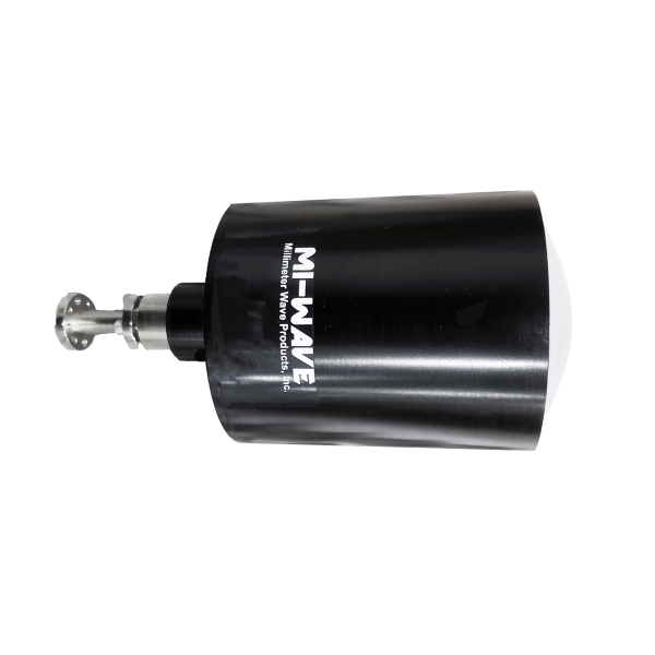
Mi-Wave’s Horn Lens Antennas (Series 258) are high-performance directional antennas designed to deliver high gain, low sidelobes, and precise beam control across RF, microwave, and millimeter-wave frequency bands from 8.2 to 170 GHz.
By combining the broadband characteristics of a horn antenna with the focusing capability of a dielectric or metal lens, these antennas provide enhanced directivity, improved aperture efficiency, and stable radiation patterns over wide frequency ranges. This hybrid design enables superior performance in applications where beam shaping, pattern control, and low distortion are critical.
Horn lens antennas are particularly well suited for high-frequency systems, where maintaining consistent performance and minimizing sidelobes is essential. Their design supports predictable radiation behavior, making them ideal for both operational deployments and controlled RF environments.
These antennas are commonly used in satellite communications, radar systems, antenna measurement ranges, RF and microwave laboratories, and millimeter-wave research applications, where high gain, stable performance, and precision beam characteristics are required.
Mi-Wave offers horn lens antennas in a variety of configurations, with options for frequency band coverage, gain levels, polarization, and mechanical design, allowing engineers to tailor solutions for specific system requirements.

| Model No. | Waveguide Band | Reflector diameter (inches) | Circular Waveguide Internal Diameter (.XXX in Model No.) in Inches | Frequency Range (GHz) | Gain (dB) (XX in Model No) | 3 dB Beamwidth (degree) | VSWR | Antenna Port | Housing material | Link |
|---|---|---|---|---|---|---|---|---|---|---|
| 258X-12/.XXX/39 | X Band | 12 | .XXX=1.094 .XXX=.938 .XXX= .797 | 8.2-9.97 8.5-11.6 9.97-12.4 | 26 | 6.5 | 1.5:1 | Circular Waveguide with UG-39/U Flange | Aluminum | |
| 258Ku-9/.XXX/419 | Ku Band | 9 | XXX=.660 XXX=.550 | 12.4-14.6 14.6-18 | 27 | 5.8 | 1.5:1 | Circular Waveguide with UG-419/U Flange | Aluminum | |
| 258Ku-12/.XXX/419 | Ku Band | 12 | XXX=.660 XXX=.550 | 12.4-14.6 14.6-18 | 30 | 4.5 | 1.5:1 | Circular Waveguide with UG-419/U Flange | Aluminum | |
| 258K-6/.XXX/595 | K Band | 6 | XXX=.470 XXX .396 XXX=.328 | 18-20.5 20.4-24.5 24.5-26.5 | 26.5 | 6 | 1.5:1 | Circular Waveguide with UG-595/U Flange or UG-425/U Flange | HDPE | |
| 258K-9/.XXX/595 | K Band | 9 | XXX=.470 XXX .396 XXX=.328 | 18-20.5 20.4-24.5 24.5-26.5 | 30 | 4 | 1.5:1 | Circular Waveguide with UG-595/U Flange or UG-425/U Flange | Aluminum | |
| 258K-12/.XXX/595 | K Band | 12 | XXX=.470 XXX .396 XXX=.328 | 18-20.5 20.4-24.5 24.5-26.5 | 33 | 3 | 1.5:1 | Circular Waveguide with UG-595/U Flange or UG-425/U Flange | Aluminum | |
| 258A-6/.XXX/599 | Ka-Band | 6 | XXX=.328 XXX=.281 XXX=.250 XXX= .219 | 26.5-28.5 28.5-33.0 33.0 -38.5 38.5-40.0 | 30 | 4.2 | 1.5:1 | Circular Waveguide with UG-599/U Flange or UG-381/U Flange | HDPE | |
| 258A-9/.XXX/599 | Ka-Band | 9 | XXX=.328 XXX=.281 XXX=.250 XXX= .219 | 26.5-28.5 28.5-33.0 33.0 -38.5 38.5-40.0 | 33 | 3 | 1.5:1 | Circular Waveguide with UG-599/U Flange or UG-381/U Flange | Aluminum | |
| 258A-12/.XXX/599 | Ka-Band | 12 | XXX=.328 XXX=.281 XXX=.250 XXX= .219 | 26.5-28.5 28.5-33.0 33.0 -38.5 38.5-40.0 | 36 | 2 | 1.5:1 | Circular Waveguide with UG-599/U Flange or UG-381/U Flange | Aluminum | |
| 258B-3/.XXX/383 | Q-band | 3 | XXX=.250 XXX=.219 XXX=.188 | 33.0-38.5 38.5-43.0 43.0-50.0 | 26 | 6.5 | 1.5:1 | Circular Waveguide with UG-383/U Flange | Aluminum | |
| 258B-6/.XXX/383 | Q-band | 6 | XXX=.250 XXX=.219 XXX=.188 | 33.0-38.5 38.5-43.0 43.0-50.0 | 32 | 3.5 | 1.5:1 | Circular Waveguide with UG-383/U Flange | HDPE | |
| 258B-9/.XXX/383 | Q-band | 9 | XXX=.250 XXX=.219 XXX=.188 | 33.0-38.5 38.5-43.0 43.0-50.0 | 36 | 2.5 | 1.5:1 | Circular Waveguide with UG-383/U Flange | Aluminum | |
| 258B-12/.XXX/383 | Q-band | 12 | XXX=.250 XXX=.219 XXX=.188 | 33.0-38.5 38.5-43.0 43.0-50.0 | 38.5 | 1.7 | 1.5:1 | Circular Waveguide with UG-383/U Flange | Aluminum | |
| 258U-3/.XXX/383 | U-band | 3 | XXX=.219 XXX=.188 XXX=.165 XXX=.141 | 38.5-43.0 43.0-50.0 50.0-58.0 58.0-60.0 | 28 | 5.5 | 1.5:1 | Circular Waveguide with UG-383/U-M Flange | Aluminum | |
| 258U-6/.XXX/383 | U-band | 6 | XXX=.219 XXX=.188 XXX=.165 XXX=.141 | 38.5-43.0 43.0-50.0 50.0-58.0 58.0-60.0 | 34 | 2.8 | 1.5:1 | Circular Waveguide with UG-383/U-M Flange | HDPE | |
| 258U-9/.XXX/383 | U-band | 9 | XXX=.219 XXX=.188 XXX=.165 XXX=.141 | 38.5-43.0 43.0-50.0 50.0-58.0 58.0-60.0 | 37.5 | 2 | 1.5:1 | Circular Waveguide with UG-383/U-M Flange | Aluminum | |
| 258U-12/.XXX/383 | U-band | 12 | XXX=.219 XXX=.188 XXX=.165 XXX=.141 | 38.5-43.0 43.0-50.0 50.0-58.0 58.0-60.0 | 39 | 1.5 | 1.5:1 | Circular Waveguide with UG-383/U-M Flange | Aluminum | |
| 258V-3/.XXX/385 | V-band | 3 | XXX=.165 XXX=.141 XXX=.125 | 50.0-58.0 58.0-68.0 68.0-75.0 | 30 | 4.5 | 1.5:1 | Circular Waveguide with UG-385/U Flange | Aluminum | |
| 258V-6/.XXX/385 | V-band | 6 | XXX=.165 XXX=.141 XXX=.125 | 50.0-58.0 58.0-68.0 68.0-75.0 | 36 | 2.5 | 1.5:1 | Circular Waveguide with UG-385/U Flange | HDPE | |
| 258V-9/.XXX/385 | V-band | 9 | XXX=.165 XXX=.141 XXX=.125 | 50.0-58.0 58.0-68.0 68.0-75.0 | 39 | 1.5 | 1.5:1 | Circular Waveguide with UG-385/U Flange | Aluminum | |
| 258V-12/.XXX/385 | V-band | 12 | XXX=.165 XXX=.141 XXX=.125 | 50.0-58.0 58.0-68.0 68.0-75.0 | 42 | 1.2 | 1.5:1 | Circular Waveguide with UG-385/U Flange | Aluminum | |
| 258E-3/.XXX/387 | E-band | 3 | XXX=.141 XXX=.125 XXX=.110 XXX=.094 | 60.0-68.0 68.0-77.0 77.0-87.0 87.0-90.0 | 31 | 3.5 | 1.5:1 | Circular Waveguide with UG-387/U Flange | Aluminum | |
| 258E-6/.XXX/387 | E-band | 6 | XXX=.141 XXX=.125 XXX=.110 XXX=.094 | 60.0-68.0 68.0-77.0 77.0-87.0 87.0-90.0 | 37 | 1.8 | 1.5:1 | Circular Waveguide with UG-387/U Flange | HDPE | |
| 258E-9/.XXX/387 | E-band | 9 | XXX=.141 XXX=.125 XXX=.110 XXX=.094 | 60.0-68.0 68.0-77.0 77.0-87.0 87.0-90.0 | 41 | 1.2 | 1.5:1 | Circular Waveguide with UG-387/U Flange | Aluminum | |
| 258E-12/.XXX/387 | E-band | 12 | XXX=.141 XXX=.125 XXX=.110 XXX=.094 | 60.0-68.0 68.0-77.0 77.0-87.0 87.0-90.0 | 43 | 1 | 1.5:1 | Circular Waveguide with UG-387/U Flange | Aluminum | |
| 258W-3/.XXX/387 | W-band | 3 | XXX=.125 XXX=.110 XXX=.094 XXX=.082 | 75.0-77.0 77.0-87.0 87.0-100.0 100.0-110.0 | 33 | 2.9 | 1.5:1 | Circular Waveguide with UG-387/U-M Flange | Aluminum | |
| 258W-6/.XXX/387 | W-band | 6 | XXX=.125 XXX=.110 XXX=.094 XXX=.082 | 75.0-77.0 77.0-87.0 87.0-100.0 100.0-110.0 | 39 | 1.5 | 1.5:1 | Circular Waveguide with UG-387/U-M Flange | HDPE | |
| 258W-9/.XXX/387 | W-band | 9 | XXX=.125 XXX=.110 XXX=.094 XXX=.082 | 75.0-77.0 77.0-87.0 87.0-100.0 100.0-110.0 | 42 | 1 | 1.5:1 | Circular Waveguide with UG-387/U-M Flange | Aluminum | |
| 258W-12/.XXX/387 | W-band | 12 | XXX=.125 XXX=.110 XXX=.094 XXX=.082 | 75.0-77.0 77.0-87.0 87.0-100.0 100.0-110.0 | 45 | 0.8 | 1.5:1 | Circular Waveguide with UG-387/U-M Flange | Aluminum | |
| 258F-3/.XXX/387 | F-band | 3 | XXX=.094 XXX=.082 XXX=.075 XXX=.067 | 87.0-100.0 100.0-112.0 112.0-125.0 125.0-140.0 | 35.5 | 2.26 | 1.5:1 | Circular Waveguide with UG-387/U-M Flange | Aluminum | |
| 258F-6/.XXX/387 | F-band | 6 | XXX=.094 XXX=.082 XXX=.075 XXX=.067 | 87.0-100.0 100.0-112.0 112.0-125.0 125.0-140.0 | 40.5 | 1.13 | 1.5:1 | Circular Waveguide with UG-387/U-M Flange | HDPE | |
| 258F-9/.XXX/387 | F-band | 9 | XXX=.094 XXX=.082 XXX=.075 XXX=.067 | 87.0-100.0 100.0-112.0 112.0-125.0 125.0-140.0 | 43.5 | 0.75 | 1.5:1 | Circular Waveguide with UG-387/U-M Flange | Aluminum | |
| 258F-12/.XXX/387 | F-band | 12 | XXX=.094 XXX=.082 XXX=.075 XXX=.067 | 87.0-100.0 100.0-112.0 112.0-125.0 125.0-140.0 | 46.5 | 0.57 | 1.5:1 | Circular Waveguide with UG-387/U-M Flange | Aluminum | |
| 258D-3/.XXX/387 | D-band | 3 | XXX=.082 XXX=.075 XXX=.067 XXX=.059 | 100.0-112.0 112.0-125.0 125.0-140.0 140.0-160.0 | 36 | 1.86 | 1.5:1 | Circular Waveguide with UG-387/U-M Flange | Aluminum | |
| 258D-6/.XXX/387 | D-band | 6 | XXX=.082 XXX=.075 XXX=.067 XXX=.059 | 100.0-112.0 112.0-125.0 125.0-140.0 140.0-160.0 | 42 | 0.93 | 1.5:1 | Circular Waveguide with UG-387/U-M Flange | HDPE | |
| 258D-9/.XXX/387 | D-band | 9 | XXX=.082 XXX=.075 XXX=.067 XXX=.059 | 100.0-112.0 112.0-125.0 125.0-140.0 140.0-160.0 | 45.5 | 0.62 | 1.5:1 | Circular Waveguide with UG-387/U-M Flange | Aluminum | |
| 258D-12/.XXX/387 | D-band | 12 | XXX=.082 XXX=.075 XXX=.067 XXX=.059 | 100.0-112.0 112.0-125.0 125.0-140.0 140.0-160.0 | 48 | 0.46 | 1.5:1 | Circular Waveguide with UG-387/U-M Flange | Aluminum |
*All data presented is collected from a sample lot.
* Actual data may vary unit to unit, slightly.
*All testing was performed under +25 °C case temperature.
*Consult factory to confirm if material, plating, size, shape, orientation and any electrical parameter is critical for the application as website information is for reference only.
*Millimeter Wave Products, Inc. reserves the right to change the information presented on website without notice as we continue to enhance the performance and design of our products.
Key Features & Performance Benefits
High Gain with Enhanced Directivity
Horn lens antennas provide strong directional gain by combining horn radiation with lens-based wavefront shaping. This results in improved directivity and efficient energy focusing across RF, microwave, and millimeter-wave frequencies.
Low Sidelobe Levels
The lens structure helps control radiation distribution, reducing sidelobes and minimizing unwanted signal radiation. This is critical for applications requiring clean beam patterns and reduced interference, such as radar and antenna measurement systems.
Wideband Frequency Operation
Horn lens antennas support broad frequency coverage, typically from 8.2 to 170 GHz, making them suitable for microwave and mmWave system
Precise Beam Shaping and Control
The addition of a lens enables refined control of the radiated wavefront, allowing for optimized beamwidth, improved pattern uniformity, and reduced distortion compared to standard horn antennas.
Improved Aperture Efficiency
Lens integration enhances aperture utilization by directing more energy into the desired radiation pattern. This leads to higher efficiency and better overall antenna performance.
Stable and Predictable Radiation Patterns
Horn lens antennas offer consistent and repeatable performance across frequency bands, making them ideal for measurement, calibration, and high-precision RF systems.
Low Phase Distortion
The lens helps maintain a uniform phase front across the aperture, reducing phase errors and improving signal quality, which is especially important in high-frequency and high-data-rate systems.
Optimized for High-Frequency Applications
These antennas are well suited for microwave and millimeter-wave systems, where tight beam control and low loss are essential for maintaining signal integrity.
Compact and Integrated Design
Compared to large reflector systems, horn lens antennas offer a more compact solution while still delivering high performance, making them suitable for laboratories, test setups, and integrated RF systems.
Flexible Configuration Options
Available in multiple sizes, frequency bands, and lens configurations, horn lens antennas can be tailored for specific requirements including gain targets, polarization, and system integration needs.
How Horn Lens Antennas Work
\Horn lens antennas operate by combining two key RF elements into a single, high-performance system: a horn antenna, which launches and transitions the signal into free space, and a lens, which refines and focuses that energy into a highly controlled beam.
Signal Launch and Expansion
The process begins with an RF signal entering through a waveguide feed. The horn antenna gradually expands this signal from a confined waveguide mode into free space. This transition improves impedance matching and reduces reflections, allowing efficient radiation.
However, at this stage, the electromagnetic wavefront is not perfectly uniform. The energy spreads outward with a slightly curved phase front, which limits maximum achievable gain and beam precision.
Phase Correction and Beam Shaping
The lens is positioned at or near the aperture of the horn and plays a critical role in improving performance. As the RF wave passes through the lens material, different portions of the wave experience controlled delays based on the lens geometry and dielectric properties.
This process effectively corrects the phase distribution across the aperture. Instead of exiting as a curved wavefront, the signal becomes more planar and uniform, which allows the energy to combine more coherently in the far field.
The result is a narrower, more focused beam with higher directivity and reduced sidelobes.
Radiation Pattern Improvement
By correcting phase errors and controlling how energy propagates, horn lens antennas achieve:
- Higher gain without significantly increasing antenna size
- Lower sidelobe levels, reducing interference and unwanted radiation
- Improved beam symmetry and pattern stability across wide frequency ranges
- Better aperture efficiency compared to standard horn antennas
This makes them especially valuable in microwave and millimeter-wave systems where small phase errors can significantly impact performance.
Why This Design Matters
At higher frequencies, such as those used in Satcom, radar, and mmWave research, wavelength becomes very small. This means even minor physical or phase inconsistencies can degrade performance.
The horn-lens design compensates for these effects by providing controlled electromagnetic focusing, ensuring that the antenna maintains predictable and repeatable radiation characteristics across broad bandwidths.
Key Specifications to Consider
When selecting or designing a horn lens antenna, several parameters directly impact performance:
Gain (dBi)
Determines how focused the beam is. Higher gain corresponds to narrower beamwidth and longer effective range.
Frequency Range (GHz)
Defines the operational bandwidth. Horn lens antennas are often designed for broadband performance across microwave and mmWave bands.
Beamwidth (Degrees)
Indicates how wide or narrow the main radiation lobe is. Narrower beamwidth provides better directionality and resolution.
Sidelobe Levels (dB)
Lower sidelobes reduce interference and improve signal clarity, which is critical in dense RF environments.
Aperture Size and Lens Geometry
The physical size and shape of the lens determine how effectively phase correction is achieved and how the beam is formed.
Polarization
Supports linear or circular polarization depending on system requirements, especially important in dual-polarized or Satcom systems.
Aperture Efficiency (%)
Measures how effectively the antenna converts input power into radiated energy. Higher efficiency indicates better overall performance.
Applications
Mi-Wave Horn Lens Antennas are widely used in RF, microwave, and millimeter-wave systems that require high gain, low sidelobes, and precise beam control. Their ability to produce stable radiation patterns with improved directivity and reduced distortion makes them ideal for both communication systems and high-precision RF environments.
These antennas support applications in satellite communications, radar systems, antenna measurement ranges, RF laboratories, and advanced research platforms, where accurate signal transmission and controlled radiation characteristics are essential.
Satellite Communications (SatCom)
Horn lens antennas are used in satellite communication systems where controlled beam shaping and low sidelobe performance are critical for maintaining signal quality and minimizing interference.
Typical satcom applications include:
- Satellite ground terminals and gateway systems
- High-frequency uplink and downlink systems
- Ka-band, Q-band, V-band, and W-band communication links
- Experimental and research-based satellite systems
- RF link validation and system testing
These antennas help improve link performance, signal clarity, and interference suppression in satellite communication environments.
Radar Systems and Testing
Horn lens antennas are widely used in radar systems due to their high directivity, low sidelobes, and precise beam control, enabling accurate target detection and signal measurement.
Common radar applications include:
- Radar cross-section (RCS) testing
- Target illumination and detection systems
- FMCW and pulse radar platforms
- Radar calibration and validation
- Microwave and millimeter-wave radar research
Their focused beam characteristics improve measurement accuracy and target resolution in radar applications.
Antenna Measurement Ranges
Horn lens antennas are commonly deployed in antenna measurement facilities where clean radiation patterns and predictable performance are required.
Typical measurement applications include:
- Antenna gain and radiation pattern measurements
- Near-field and far-field testing
- Calibration of RF antennas and measurement equipment
- Beamwidth and sidelobe verification
- RF system validation
Low sidelobe levels and stable beam characteristics make these antennas ideal for precision measurement environments.
RF and Microwave Laboratory Research
Research laboratories and engineering teams use horn lens antennas for high-frequency system development and experimental RF studies.
Typical research applications include:
- Millimeter-wave system prototyping
- Wireless propagation experiments
- RF component and subsystem testing
- Advanced antenna research and development
- Academic and government research programs
These antennas provide a reliable platform for repeatable and accurate RF experimentation.
EMC and RF Testing
Horn lens antennas are also used in electromagnetic compatibility (EMC) environments where controlled radiation and minimal interference are required.
Common EMC applications include:
- Radiated emissions testing
- RF susceptibility testing
- Controlled illumination of test devices
- EMC compliance verification
- Shielding effectiveness testing
Their directional performance allows engineers to focus RF energy precisely, improving test accuracy and repeatability.
Frequently Asked Questions (FAQ)
What is a horn lens antenna?
A horn lens antenna is a directional antenna that combines a horn radiator with a dielectric or metal lens to improve beam focusing, increase gain, and reduce sidelobes. This design enhances radiation control compared to standard horn antennas.
What are the advantages of horn lens antennas?
Horn lens antennas offer high gain, low sidelobes, improved directivity, and precise beam control. They are especially useful in high-frequency systems where clean radiation patterns and minimal distortion are required.
What frequencies do horn lens antennas support?
Horn lens antennas typically operate across microwave and millimeter-wave frequencies, commonly from 8.2 GHz to 110 GHz, depending on design and configuration.
How do horn lens antennas improve performance over standard horn antennas?
The lens modifies the electromagnetic wavefront, improving aperture efficiency, beam uniformity, and sidelobe suppression, resulting in better overall antenna performance.
What determines gain in a horn lens antenna?
Antenna gain is determined by aperture size, operating frequency, and efficiency. Larger apertures and higher frequencies generally result in higher gain.
What is beamwidth in a horn lens antenna?
Beamwidth is the angular width of the main radiation beam. Horn lens antennas produce narrow, well-controlled beamwidths, improving signal focus and measurement accuracy.
What are horn lens antennas used for?
Horn lens antennas are used in:
- Satellite communications (SatCom)
- Radar systems
- Antenna measurement ranges
- RF and microwave laboratories
- EMC and RF testing
- Millimeter-wave research
Are horn lens antennas suitable for measurement applications?
Yes. Their low sidelobe levels and stable radiation patterns make them ideal for antenna calibration, gain measurements, and precision RF testing.
Can horn lens antennas be customized?
Yes. Horn lens antennas can be customized for frequency range, gain, lens type, polarization, and mechanical configuration to meet specific system requirements.
What materials are used in horn lens antennas?
Horn lens antennas typically use precision metal waveguide horns combined with dielectric (plastic) or metal lenses, depending on frequency, performance requirements, weight considerations, and environmental conditions.
Why use a dielectric (plastic) lens in a horn antenna?
Dielectric (plastic) lenses are often used to reduce weight while maintaining effective beam shaping and high-frequency performance. They also allow for more flexible designs in laboratory, field, and integrated RF systems.
Horn Lens Antenna Engineering Calculators
Quickly estimate key performance metrics for horn lens antennas used in RF and millimeter-wave systems. These calculators help engineers determine gain, beamwidth, aperture efficiency, wavelength, and path loss, enabling faster design decisions for SatCom, radar, test and measurement, and research applications.
Spot Focus Antenna Engineering Calculators
These RF engineering calculators help estimate antenna performance for spot focus antennas, including communications systems, radar platforms, antenna measurement ranges, and microwave and millimeter-wave test environments. Use them to calculate antenna gain, beamwidth, reflector diameter required for target gain, effective aperture, free-space path loss, and wavelength across RF, microwave, and millimeter-wave frequencies.
Spot focus antennas are designed for tight beamwidth, focused energy distribution, and strong directional performance. A typical starting efficiency range for many systems is 0.50 to 0.70.
Antenna Gain Calculator
Antenna Gain (dBi):
Antenna Beamwidth Calculator
Reflector Size Required for Target Gain
Antenna Effective Aperture Calculator
Effective Aperture (m²):
Free Space Path Loss Calculator
RF Wavelength Calculator
Wavelength (mm):
Glossary of Horn Lens Antenna Terms
This glossary defines key terminology related to horn lens antennas used in RF, microwave, and millimeter-wave systems where high gain, beam shaping, and low sidelobe performance are critical. These antennas are widely used in satellite communications, radar systems, antenna measurement ranges, RF laboratories, EMC testing, and advanced research applications.
Antenna Fundamentals
Horn Lens Antenna
A hybrid antenna that combines a horn radiator with a lens to improve gain, directivity, and beam control.
Horn Antenna
A flared waveguide structure used to radiate RF energy with controlled directivity and broadband performance.
RF Lens
A structure that focuses or shapes electromagnetic waves to improve antenna performance and beam characteristics.
Dielectric Lens
A lens made from non-conductive materials (often plastic) that refracts RF energy to improve beam focusing and reduce sidelobes.
Metal Lens
A lens constructed from conductive materials used to shape RF wavefronts, typically in specialized or high-power applications.
Aperture
The opening through which RF energy is radiated or received.
Aperture Area
The physical area of the antenna opening, directly influencing gain and beamwidth.
Radiation Characteristics
Antenna Gain
A measure of how effectively an antenna directs RF energy in a specific direction.
Directivity
The degree to which an antenna concentrates energy in a preferred direction.
Beamwidth
The angular width of the main radiation beam.
Half-Power Beamwidth (HPBW)
The angle between points where the signal level drops by 3 dB from the peak.
Sidelobes
Secondary radiation peaks outside the main beam that can cause interference or measurement errors.
Radiation Pattern
A representation of how RF energy is distributed in space.
Phase Front
The shape of the electromagnetic wave as it propagates through space.
Performance and Efficiency
Aperture Efficiency
The effectiveness of the antenna in utilizing its physical aperture to produce gain.
Effective Aperture (Ae)
The area over which the antenna effectively captures or radiates usable RF energy.
Lens Efficiency
The effectiveness of the lens in shaping and directing RF energy without excessive loss.
Phase Error
Deviation from a uniform phase distribution across the antenna aperture, which can degrade performance.
Insertion Loss
Loss of signal power caused by materials, lens properties, or transitions within the antenna.
Spillover Loss
RF energy that radiates outside the intended aperture or beam path, reducing efficiency.
RF and Frequency Terms
Radio Frequency (RF)
Electromagnetic frequencies used for communication, radar, and sensing systems.
Microwave Frequencies
Typically 1 GHz to 30 GHz.
Millimeter-Wave (mmWave)
Typically 30 GHz to 300 GHz.
Wavelength (λ)
The physical distance between repeating peaks of an electromagnetic wave.
Frequency (f)
The number of wave cycles per second, typically measured in GHz for RF systems.
Applications and Systems
Satellite Communications (SatCom)
Systems that use satellites to transmit and receive RF signals over long distances.
Radar Systems
Systems that use RF signals to detect, track, and measure objects.
Antenna Measurement Range
A controlled environment used to evaluate antenna gain, beam patterns, and performance.
EMC Testing
Testing to ensure devices operate without causing or receiving electromagnetic interference.
RF Test Systems
Equipment used to analyze and validate RF performance in laboratory or production environments.
Frequency Bands
- L-Band: 1–2 GHz
- S-Band: 2–4 GHz
- C-Band: 4–8 GHz
- X-Band: 8–12 GHz
- Ku-Band: 12–18 GHz
- Ka-Band: 26–40 GHz
- Q-Band: 33–50 GHz
- V-Band: 50–75 GHz
- W-Band: 75–110 GHz
These bands are commonly used in satellite communications, radar systems, wireless links, and millimeter-wave research applications.
Outlines & Drawings
Find your band and view outlines, drawings, data & more.
Horn Lens Antenna Manufacturer
Why Choose Mi-Wave for Horn Lens Antennas
Mi-Wave manufactures a broad range of horn lens corrected antennas designed to support RF, microwave, and millimeter-wave applications. Our experienced sales engineering team works directly with customers to answer technical questions, recommend the right antenna solution, and support custom requirements.
As a leading global supplier of microwave and millimeter-wave products, Mi-Wave has the expertise and manufacturing capability to meet a wide variety of performance, frequency, and application needs. Our horn lens antenna offerings include multiple configurations to support different beam patterns, gain requirements, and system architectures.
Horn Types Available:
-
Sectoral Horn Antennas for controlled beam shaping in one plane
-
Pyramidal Horn Antennas for balanced beamwidth and wideband performance
-
Conical Horn Antennas for symmetrical radiation patterns and high directivity
Custom horn lens antenna designs are available to meet specific frequency bands, gain targets, polarization requirements, and mechanical constraints.
What This Product Does
High-Gain, Wideband Antenna Radiation
Horn lens antennas are specialized antennas that use a horn feed to launch electromagnetic waves into a lens structure, which then focuses and shapes the beam. The horn feed provides a broadband match to the transmission line, while the lens enhances directivity, gain, and control over sidelobe levels.
By focusing RF energy into a tighter beam, horn lens antennas improve signal reach, reduce interference, and support high-precision communications and measurement tasks. This combination of broadband feed and lens focusing enables stable performance across wide frequency ranges.
Why Gain and Beam Control Matter
In many RF and microwave systems, gain and beam pattern directly impact system performance:
-
Higher gain increases effective radiated power and improves link reliability.
-
Narrow beamwidth enhances spatial resolution and reduces off-axis interference.
-
Stable radiation patterns support consistent system behavior across frequency bands.
Horn lens antennas are particularly useful in systems requiring directional control, long-range communication, signal testing, and precision measurement.
Typical Uses and Applications
Horn lens antennas are widely used in:
-
Wireless communication links
-
Millimeter-wave and microwave communications
-
Radar systems and tracking applications
-
Test and measurement environments
-
Antenna pattern and gain verification
-
Point-to-point communication systems
-
Satellite ground station terminals
-
Scientific and research instrumentation
These antennas deliver consistent high gain, reliable beam control, and repeatable performance needed in critical RF environments.
Key Features
-
High gain with focused beam patterns
-
Wideband performance across RF, microwave, and millimeter-wave bands
-
Stable radiation patterns and low sidelobe levels
-
Effective for both lab and field deployment
-
Precision mechanical design for repeatable results
-
Support for multiple polarizations and mounts
-
Rugged construction for reliable long-term use
-
Custom variations available for specific applications