
Trihedral Reflectors for Radar Applications
Published by: Mi-Wave© (Millimeter Wave Products Inc.)
Authored by: Mark Smith, Lokesh Saggam, Shashi Saggam
Introduction
A corner reflector is a passive device used to reflect radio waves back toward the emission source directly. Therefore, corner reflector is a useful device for Radar system calibration. In general, the corner reflector consists mutually intersected perpendicular plates. The commonly seen corner reflectors are dihedral and trihedral.
Corner reflectors are used to generate a particularly strong radar echo from objects that would otherwise have only very low effective Radar cross section (RCS). A corner reflector consisting of two or three electrically conductive surfaces which are mounted crosswise (at an angle of exactly 90 degrees). Incoming electromagnetic waves are backscattered by multiple reflection accurately in that direction from which they come. Thus, even small objects with small RCS yield a sufficiently strong echo. The larger a corner reflector is, the more energy is reflected. Trihedral corner reflectors are the preferred canonical target for SAR performance evaluation for many radar developments programs.
Advantages and Disadvantages
Trihedral corner reflectors are a canonical radar reflector frequently used to calibrate or gauge the performance of radar systems.
They offer the following desirable attributes.
- Fairly large Radar Cross Section (RCS) for its size.
- Fairly broad range of aspect angles with a large RCS.
- Theoretical RCS easily calculated as a function of aspect angle.
- The trihedral corner reflect is highly tolerant to the misalignment, which offers a convenient way for quick field setup.
- They are physically smaller and yield a wider half-power response. The wider half-power response of the triangular reflector, the more leeway there will be for alignment between the radar and the calibration target.

However, the following undesirable attributes also exist.
• The equations often provided for theoretical RCS assume the trihedral exists in free space, independent of surrounding environmental reflectors such as the ground.
• The RCS falls off rather dramatically as aspect angles approach parallel with the plates that make up the reflector.
• If a trihedral is tilted forward so that its direction of maximum RCS is at a shallow grazing angle with respect to the ground, then ground-lobing becomes problematic, diminishing the accuracy of the RCS calculations.
• If the trihedral is placed such that the bottom plate is parallel to the ground, then the RCS of the trihedral is severely diminished at low grazing angles with respect to the ground.
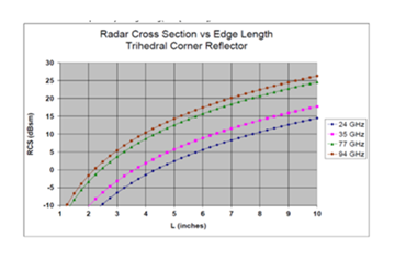
Trihedral Reflector’s RCS, Edge length and Frequency Correlation
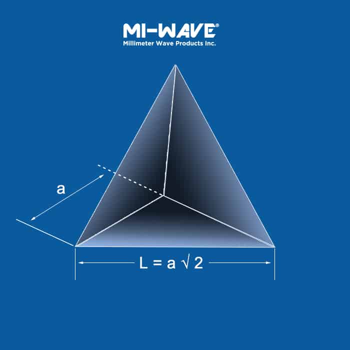
The trihedral corner reflector is made with three right angle plates, which is illustrated in the figure below.
The effective area is calculated by:
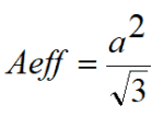
Where “a” is the edge length of the trihedral.
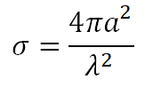
The effective radar cross section is calculated by:
RCS vs Edge Length at different frequencies
Radar cross section (RCS): is the measure of a target’s ability to reflect radar signals in the direction of the radar receiver, i.e. it is a measure of the ratio of backscatter power per steradian (unit solid angle) in the direction of the radar (from the target) to the power density that is intercepted by the target.
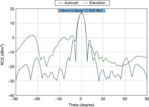
General Radiation pattern
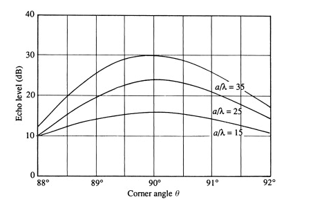
The Accuracy of Construction
The angle between each pair of planes must be 90° and very little error can be tolerated without affecting the efficient operation of the corner. Where, as a result of damage or careless construction, the angle is other than 90°, even by a very small amount, the response from the corner can be seriously impaired.
Target based RCS
The RCS of a complex target, such as a ship or aircraft, depends on the look angle of the radar. As the geometry of the target’s scattering points changes aspect with motion, the target’s RCS varies, or scintillates. The same phenomenon takes place when the radar frequency changes because the relative position of the target scatterers, measured at different wavelengths, changes. Lastly, σ is polarization dependent. Given that we have no a prior knowledge of the shape and polarization properties of the target, the possession of a full polarization capability of a system ensures that maximum information of the scene containing targets and clutter is attained, σ is therefore time, frequency, polarization, and look-angle dependent.
Moving targets can be discriminated from some clutter because the returns from clutter have zero Doppler shift, and the RCS of a target scintillates whereas that of clutter remains constant.
For the purposes of calculating the range of a target, some designers assume that σ is the time-average RCS of the target at one polarization. Measurements of σ of complex targets at different polarizations and frequencies, as well as approaches to minimize it, form an established field of research.
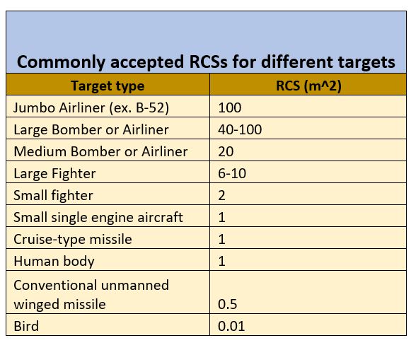
As might be expected, the RCSs of combat aircraft as a function of look angle, polarization, and frequency are not available in the open literature. In the recent past, designers have accepted the figures of 1, 10, and 100 m2 for the RCSSs corresponding to cruise-type missiles, fighter planes, and bombers, respectively.

How to Order & Custom Products
As the manufacturing source, we have top sales engineers ready to answer all your questions and quote you on product needs. You’ll find our prices are some of the best since we manufacture all our millimeter wave products in house.
Have a custom job or unique need? No problem! Contact us so we can work on solutions to meet your needs.
2007 Gandy Blvd N
Suite 1310
St. Petersburg, FL 33702
Tel: 727-563-0034
Fax: 727-563-0031
Email: sales@miwv.com