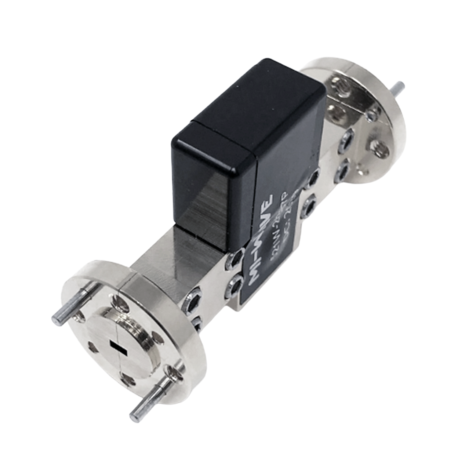
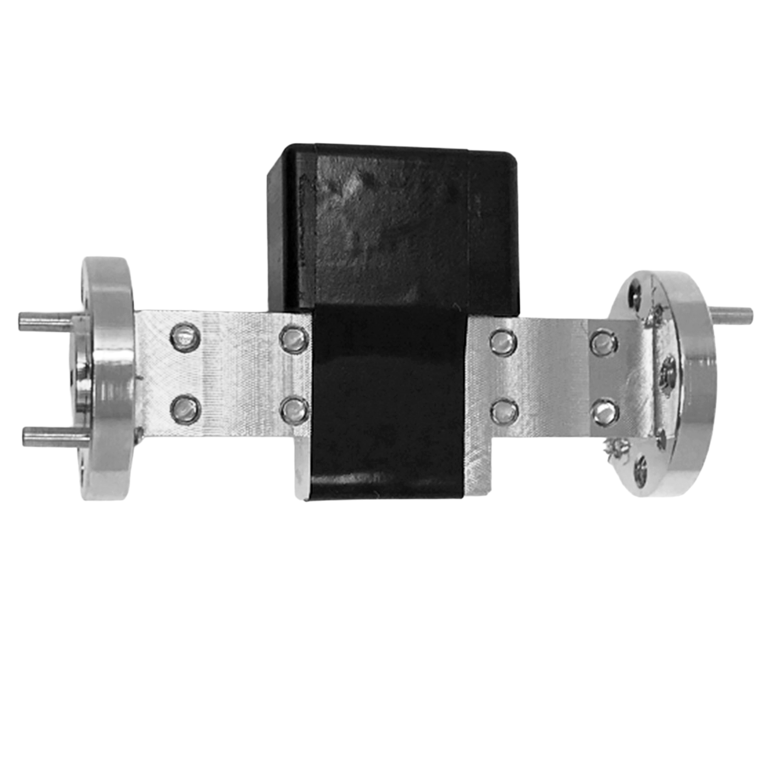
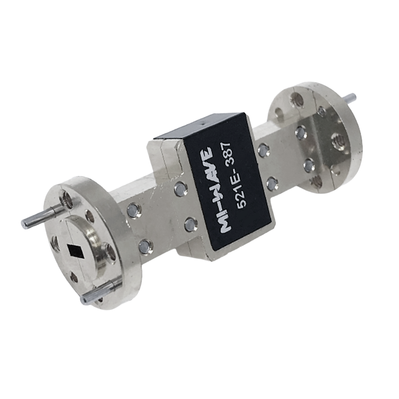
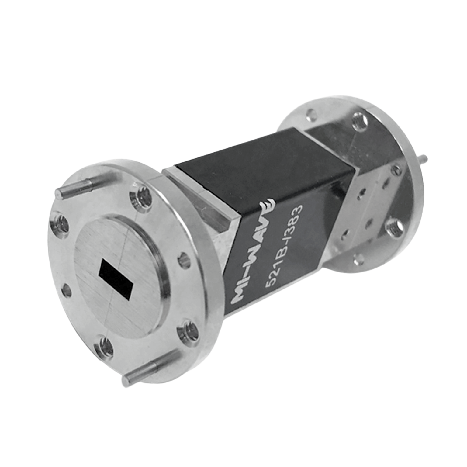
Fixed Attenuators
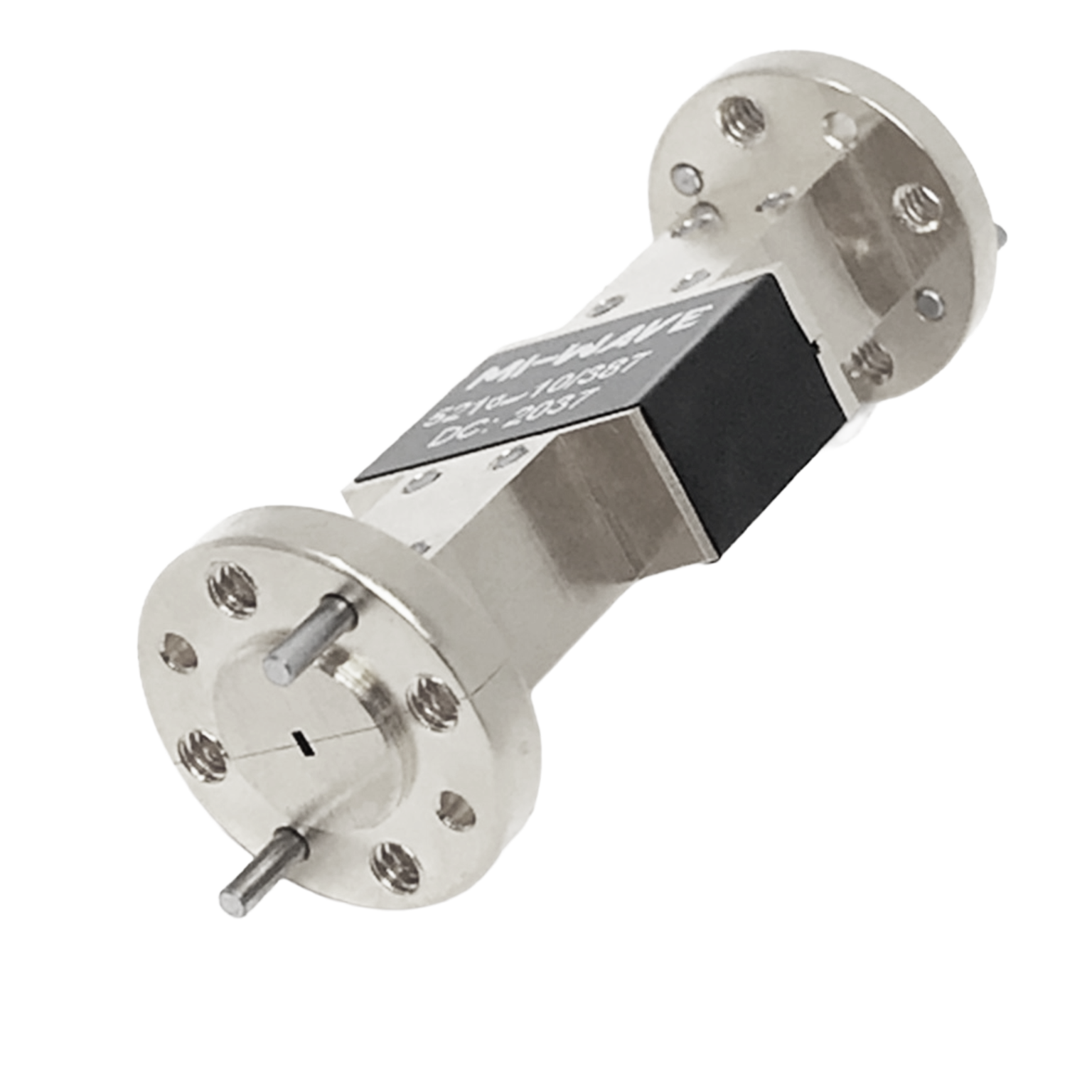
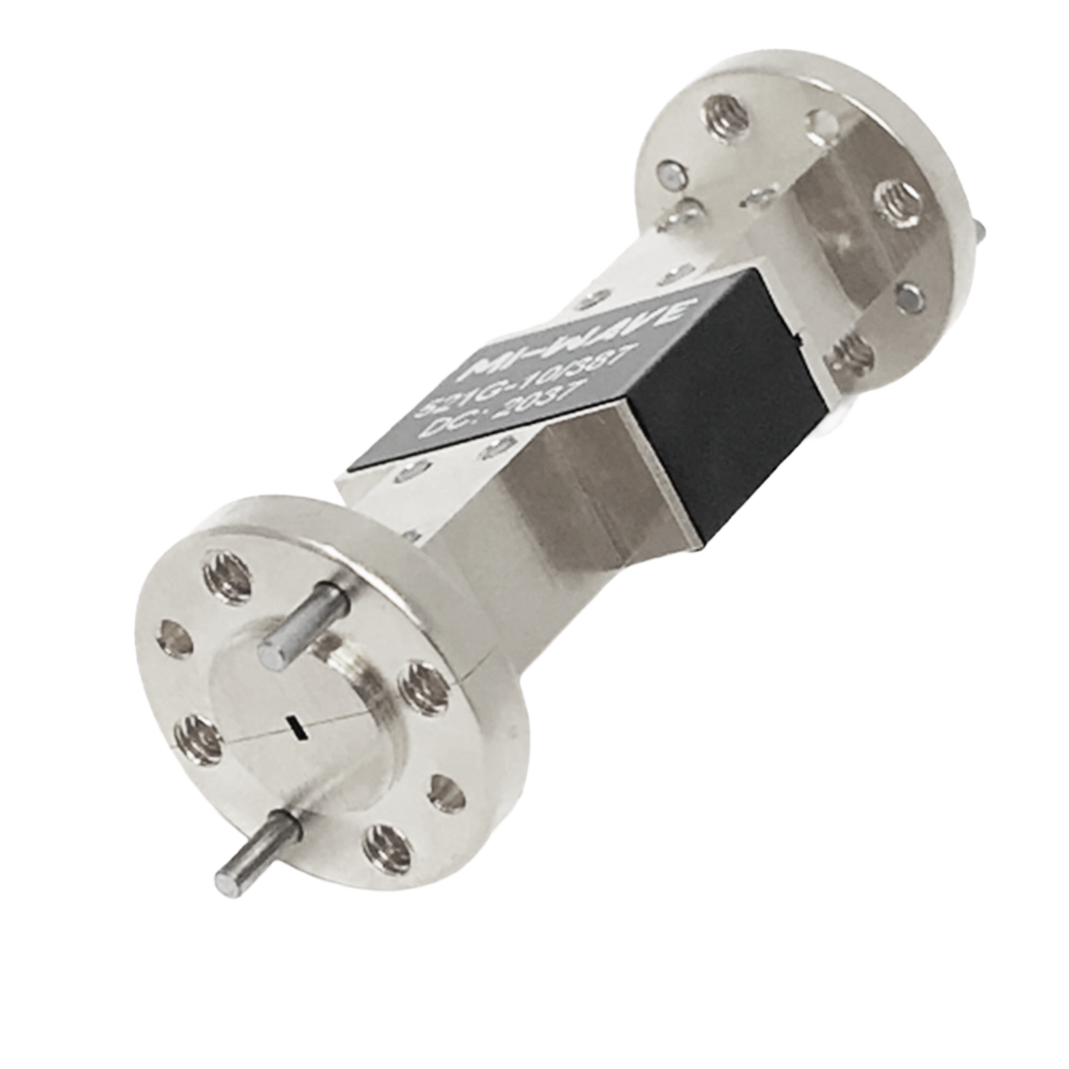
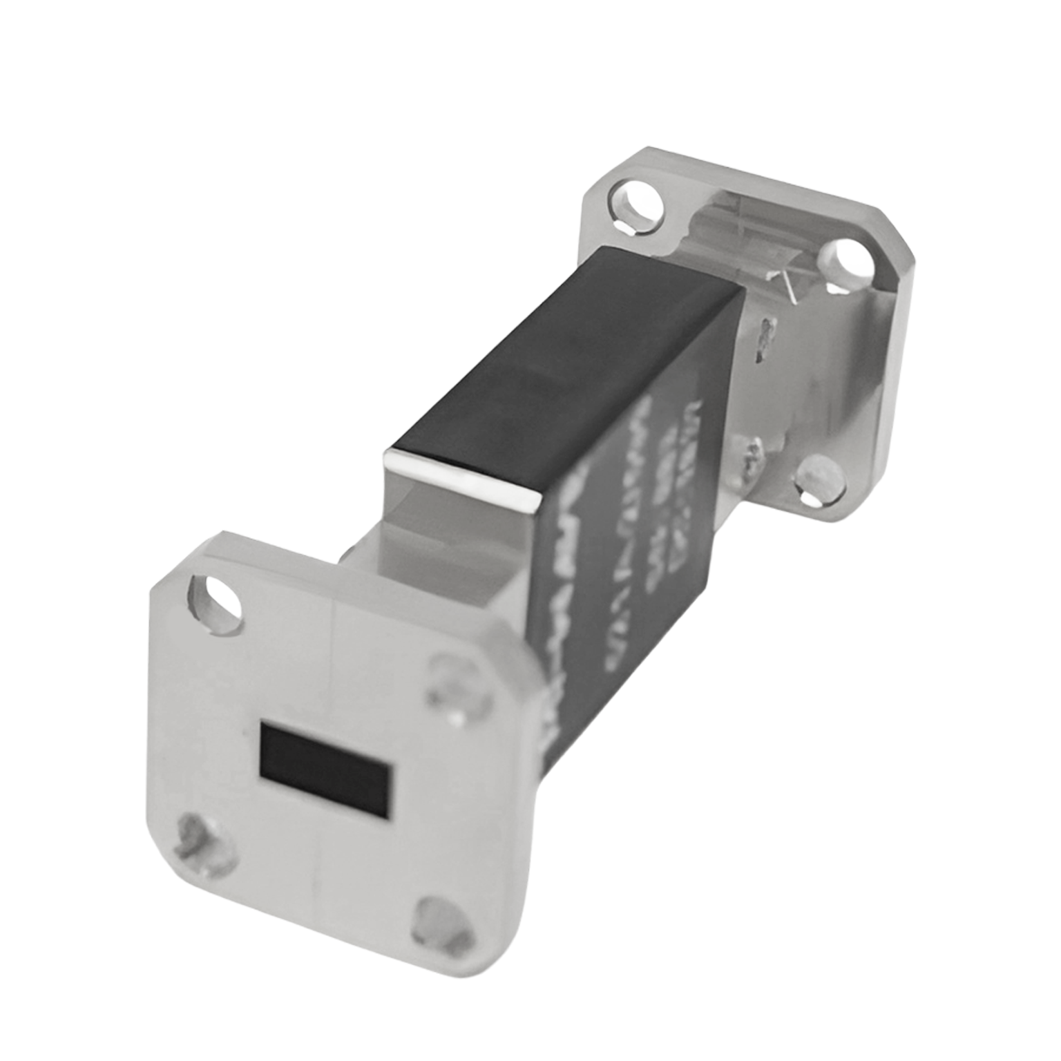
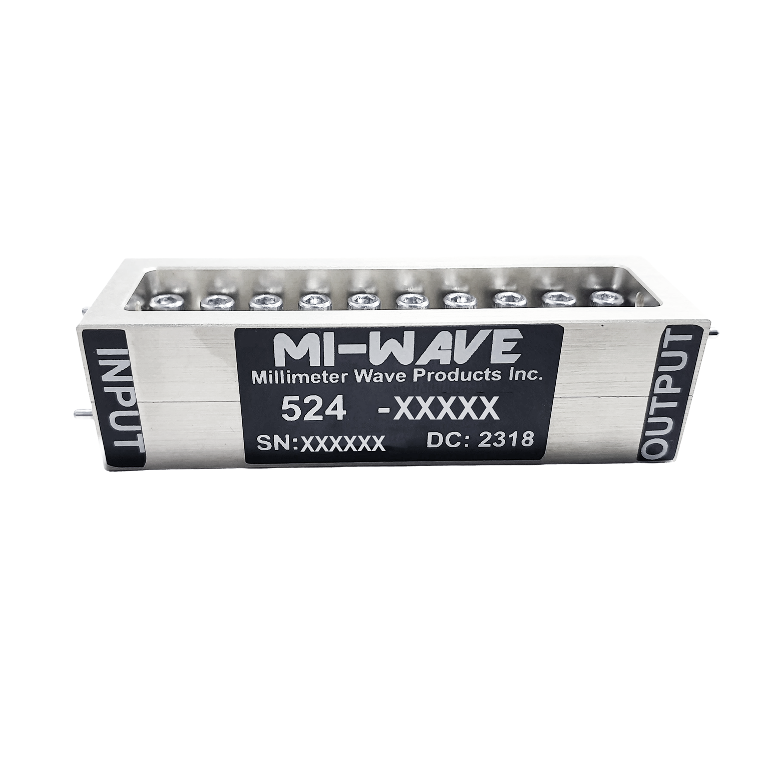
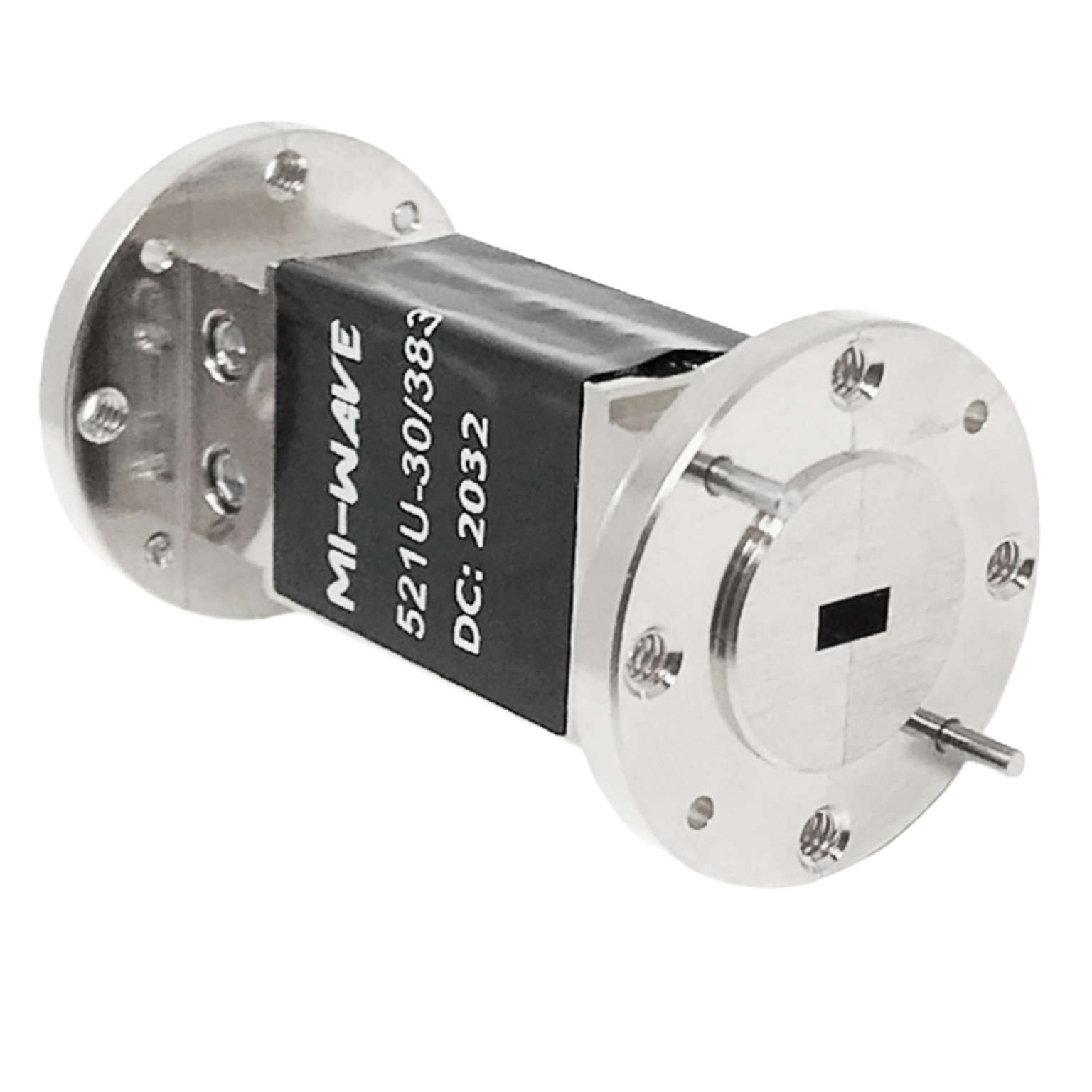
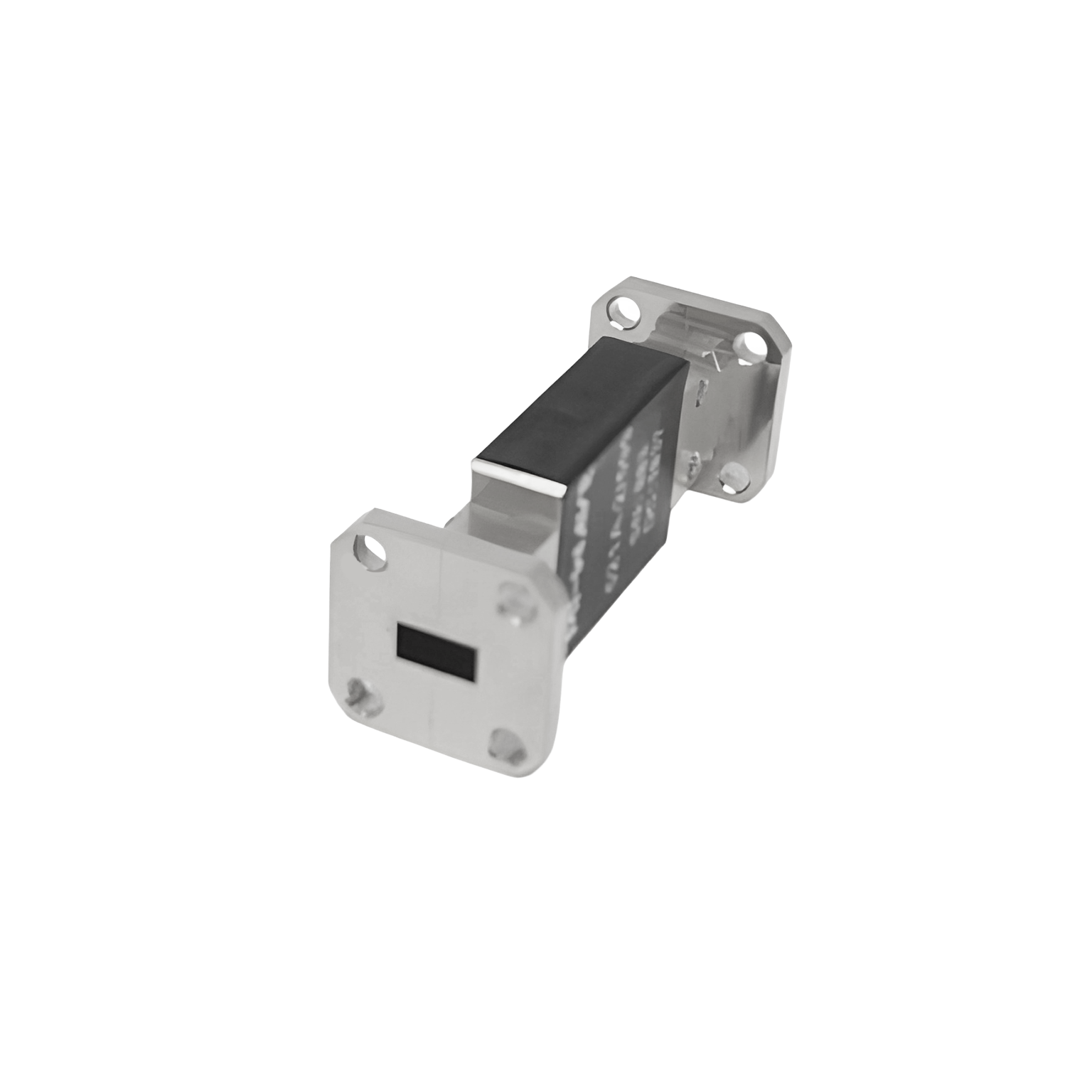
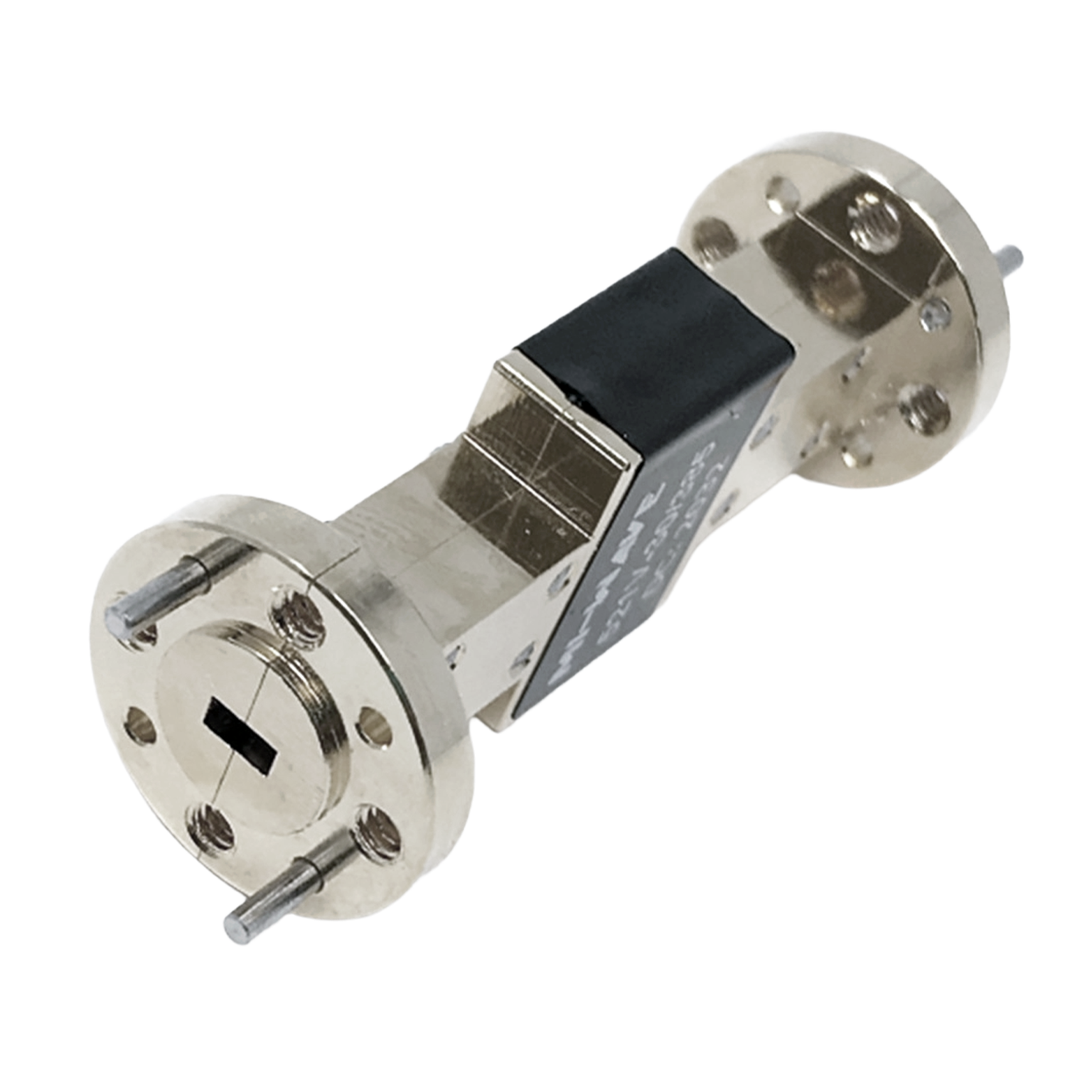
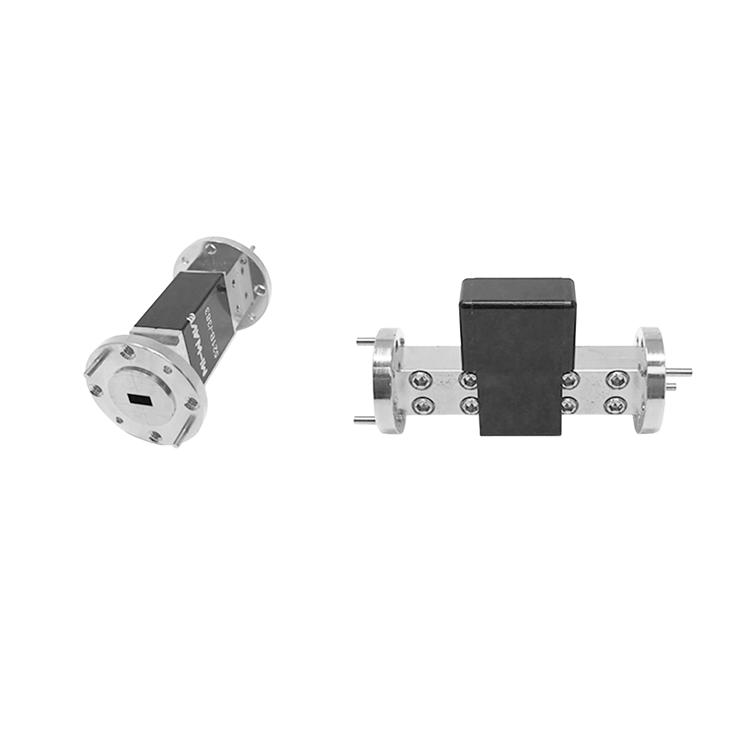
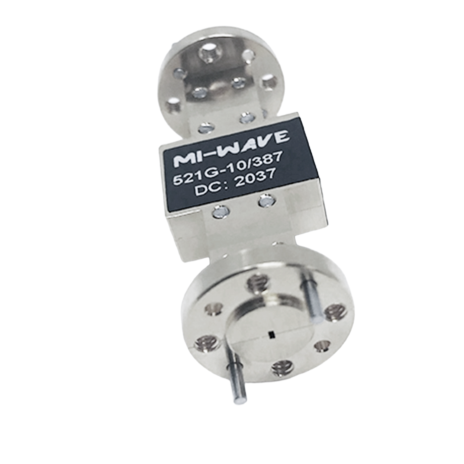
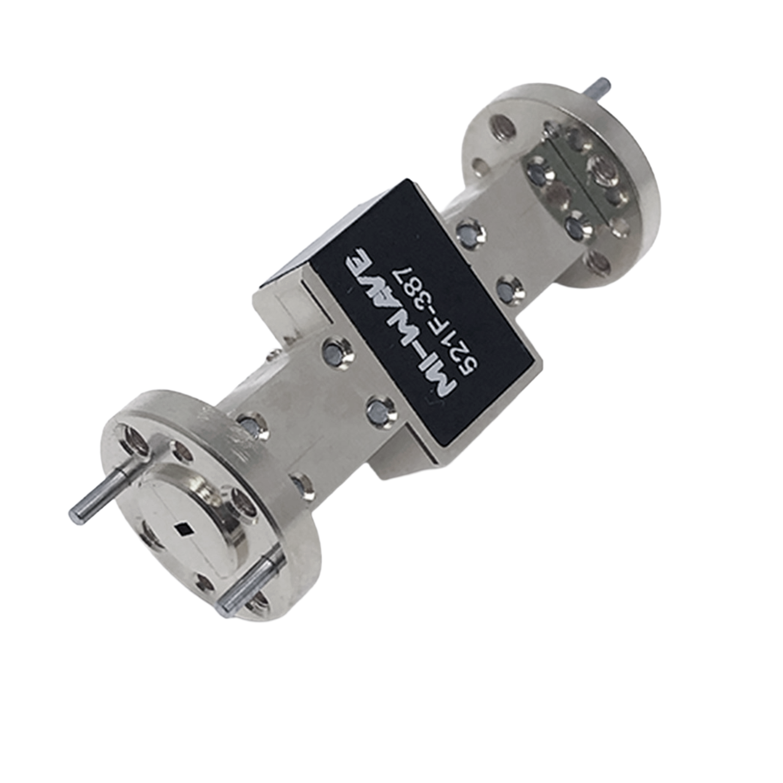
Mi-Wave’s 521 Series Fixed Attenuators and 524 High Power Series Fixed Attenuators are precision waveguide components designed to provide accurate, repeatable fixed attenuation across standard waveguide bands from 8 GHz to 220 GHz. Available in attenuation values from 6 dB to 30 dB, these attenuators are used in microwave and millimeter-wave systems where stable signal reduction, improved measurement accuracy, and dependable waveguide performance are required.
Each fixed attenuator is calibrated at the exact frequency specified at the time of order and is designed to achieve accuracy within 0.1 dB or 1%, supporting precise signal level control in demanding RF and mmWave applications. The 521 Series is well suited for general fixed attenuation needs in laboratory, instrumentation, and test systems, while the 524 Series is intended for applications that require higher power handling.
All 521 Series units are H-plane fixed attenuators, making them especially useful in waveguide transmission lines where accurate fixed attenuation and consistent performance are critical. These attenuators are commonly used to isolate generators from mismatched load effects, extend the usable frequency range of power measurement equipment, and accurately reduce signal source output levels in microwave and millimeter-wave systems.
Built for dependable laboratory and system use, Mi-Wave fixed attenuators provide a practical solution for engineers who need known, stable attenuation values without the complexity of adjustable attenuation devices.
The standard models shown represent only part of Mi-Wave’s broader product capabilities. Custom configurations are available to support specific frequency bands, interfaces, and application requirements, enabling optimized solutions for specialized RF, microwave, and millimeter-wave systems.
Note: Our website contains just a few types of Attenuators we build. Consult with us for your specific needs.
| Model | Band Type | Power Handling | Minimum Frequency (GHz) | Maximum Frequency (GHz) | Attenuation (dB) | Power Handling (CW) | RF Ports | LINK |
|---|---|---|---|---|---|---|---|---|
| 521K-3/595 | K-Band | LOW | 18 | 26.5 | 3 | 10 | WR-42 Waveguide UG-595/U Flange | |
| 521K-6/595 | K-Band | LOW | 18 | 26.5 | 6 | 10 | WR-42 Waveguide UG-595/U Flange | |
| 521K-10/595 | K-Band | LOW | 18 | 26.5 | 10 | 10 | WR-42 Waveguide UG-595/U Flange | |
| 521K-20/595 | K-Band | LOW | 18 | 26.5 | 20 | 10 | WR-42 Waveguide UG-595/U Flange | |
| 521K-30/595 | K-Band | LOW | 18 | 26.5 | 30 | 10 | WR-42 Waveguide UG-595/U Flange | |
| 524K-6/595 | K-Band | HIGH | 18 | 26.5 | 6 | 150 | WR-42 Waveguide UG-595/U Flange | |
| 524K-10/595 | K-Band | HIGH | 18 | 26.5 | 10 | 150 | WR-42 Waveguide UG-595/U Flange | |
| 524K-20/595 | K-Band | HIGH | 18 | 26.5 | 20 | 150 | WR-42 Waveguide UG-595/U Flange | |
| 524K-30/595 | K-Band | HIGH | 18 | 26.5 | 30 | 150 | WR-42 Waveguide UG-595/U Flange | |
| 521A-2/599 | Ka-Band | LOW | 26.5 | 40 | 2 | 10 | WR-42 Waveguide UG-599/U Flange | |
| 521A-3/599 | Ka-Band | LOW | 26.5 | 40 | 3 | 10 | WR-42 Waveguide UG-599/U Flange | |
| 521A-5/599 | Ka-Band | LOW | 26.5 | 40 | 5 | 10 | WR-42 Waveguide UG-599/U Flange | |
| 521A-10/599 | Ka-Band | LOW | 26.5 | 40 | 10 | 10 | WR-42 Waveguide UG-599/U Flange | |
| 521A-20/599 | Ka-Band | LOW | 26.5 | 40 | 20 | 10 | WR-42 Waveguide UG-599/U Flange | |
| 521A-30/599 | Ka-Band | LOW | 26.5 | 40 | 30 | 10 | WR-42 Waveguide UG-599/U Flange | |
| 524A-6/599 | Ka-Band | HIGH | 26.5 | 40 | 6 | 75 | WR-42 Waveguide UG-599/U Flange | |
| 524A-10/599 | Ka-Band | HIGH | 26.5 | 40 | 10 | 75 | WR-42 Waveguide UG-599/U Flange | |
| 524A-20/599 | Ka-Band | HIGH | 26.5 | 40 | 20 | 75 | WR-42 Waveguide UG-599/U Flange | |
| 524A-30/599 | Ka-Band | HIGH | 26.5 | 40 | 30 | 75 | WR-42 Waveguide UG-599/U Flange | |
| 524B-10/383 | Q-Band | HIGH | 33 | 50 | 10 | 20 | WR-22 Waveguide UG-383/U Flange | |
| 524B-20/383 | Q-Band | HIGH | 33 | 50 | 20 | 20 | WR-22 Waveguide UG-383/U Flange | |
| 524B-30/383 | Q-Band | HIGH | 33 | 50 | 30 | 20 | WR-22 Waveguide UG-383/U Flange | |
| 521B-3/383 | Q-Band | LOW | 33 | 50 | 3 | 7 | WR-22 Waveguide UG-383/U Flange | |
| 521B-5/383 | Q-Band | LOW | 33 | 50 | 5 | 7 | WR-22 Waveguide UG-383/U Flange | |
| 521B-10/383 | Q-Band | LOW | 33 | 50 | 10 | 7 | WR-22 Waveguide UG-383/U Flange | |
| 521B-20/383 | Q-Band | LOW | 33 | 50 | 20 | 7 | WR-22 Waveguide UG-383/U Flange | |
| 521B-30/383 | Q-Band | LOW | 33 | 50 | 30 | 7 | WR-22 Waveguide UG-383/U Flange | |
| 521U-3/383 | U-Band | LOW | 40 | 60 | 3 | 5 | WR-19 Waveguide UG-383/U-M Flange | |
| 521U-6/383 | U-Band | LOW | 40 | 60 | 6 | 5 | WR-19 Waveguide UG-383/U-M Flange | |
| 521U-10/383 | U-Band | LOW | 40 | 60 | 10 | 5 | WR-19 Waveguide UG-383/U-M Flange | |
| 521U-20/383 | U-Band | LOW | 40 | 60 | 20 | 5 | WR-19 Waveguide UG-383/U-M Flange | |
| 521U-30/383 | U-Band | LOW | 40 | 60 | 30 | 5 | WR-19 Waveguide UG-383/U-M Flange | |
| 524U-6/383 | U-Band | HIGH | 40 | 60 | 6 | 10 | WR-19 Waveguide UG-383/U-M Flange | |
| 524U-10/383 | U-Band | HIGH | 40 | 60 | 10 | 10 | WR-19 Waveguide UG-383/U-M Flange | |
| 524U-20/383 | U-Band | HIGH | 40 | 60 | 20 | 10 | WR-19 Waveguide UG-383/U-M Flange | |
| 524U-30/383 | U-Band | HIGH | 40 | 60 | 30 | 10 | WR-19 Waveguide UG-383/U-M Flange | |
| 521V-3/385 | V-Band | LOW | 50 | 75 | 3 | 5 | WR-15 Waveguide UG-385/U Flange | |
| 521V-6/385 | V-Band | LOW | 50 | 75 | 6 | 5 | WR-15 Waveguide UG-385/U Flange | |
| 521V-10/385 | V-Band | LOW | 50 | 75 | 10 | 5 | WR-15 Waveguide UG-385/U Flange | |
| 521V-20/385 | V-Band | LOW | 50 | 75 | 20 | 5 | WR-15 Waveguide UG-385/U Flange | |
| 521V-30/385 | V-Band | LOW | 50 | 75 | 30 | 5 | WR-15 Waveguide UG-385/U Flange | |
| 524V-6/385 | V-Band | HIGH | 50 | 75 | 6 | 10 | WR-15 Waveguide UG-385/U Flange | |
| 524V-10/385 | V-Band | HIGH | 50 | 75 | 10 | 10 | WR-15 Waveguide UG-385/U Flange | |
| 524V-20/385 | V-Band | HIGH | 50 | 75 | 20 | 10 | WR-15 Waveguide UG-385/U Flange | |
| 524V-30/385 | V-Band | HIGH | 50 | 75 | 30 | 10 | WR-15 Waveguide UG-385/U Flange | |
| 521E-3/387 | E-Band | LOW | 60 | 90 | 3 | 2 | WR-12 Waveguide UG-387/U Flange | |
| 521E-6/387 | E-Band | LOW | 60 | 90 | 6 | 2 | WR-12 Waveguide UG-387/U Flange | |
| 521E-10/387 | E-Band | LOW | 60 | 90 | 10 | 2 | WR-12 Waveguide UG-387/U Flange | |
| 521E-20/387 | E-Band | LOW | 60 | 90 | 20 | 2 | WR-12 Waveguide UG-387/U Flange | |
| 521E-30/387 | E-Band | LOW | 60 | 90 | 30 | 2 | WR-12 Waveguide UG-387/U Flange | |
| 524E-6/387 | E-Band | HIGH | 60 | 90 | 6 | 10 | WR-12 Waveguide UG-387/U Flange | |
| 524E-10/387 | E-Band | HIGH | 60 | 90 | 10 | 10 | WR-12 Waveguide UG-387/U Flange | |
| 524E-20/387 | E-Band | HIGH | 60 | 90 | 20 | 10 | WR-12 Waveguide UG-387/U Flange | |
| 524E-30/387 | E-Band | HIGH | 60 | 90 | 30 | 10 | WR-12 Waveguide UG-387/U Flange | |
| 521W-3/387 | W-Band | LOW | 75 | 110 | 3 | 2 | WR-10 Waveguide UG-387/U-M Flange | |
| 521W-6/387 | W-Band | LOW | 75 | 110 | 6 | 2 | WR-10 Waveguide UG-387/U-M Flange | |
| 521W-10/387 | W-Band | LOW | 75 | 110 | 10 | 2 | WR-10 Waveguide UG-387/U-M Flange | |
| 521W-20/387 | W-Band | LOW | 75 | 110 | 20 | 2 | WR-10 Waveguide UG-387/U-M Flange | |
| 521W-30/387 | W-Band | LOW | 75 | 110 | 30 | 2 | WR-10 Waveguide UG-387/U-M Flange | |
| 524W-6/387 | W-Band | HIGH | 75 | 110 | 6 | 10 | WR-10 Waveguide UG-387/U-M Flange | |
| 524W-10/387 | W-Band | HIGH | 75 | 110 | 10 | 10 | WR-10 Waveguide UG-387/U-M Flange | |
| 524W-20/387 | W-Band | HIGH | 75 | 110 | 20 | 10 | WR-10 Waveguide UG-387/U-M Flange | |
| 524W-30/387 | W-Band | HIGH | 75 | 110 | 30 | 10 | WR-10 Waveguide UG-387/U-M Flange | |
| 521F-3/387 | F-Band | LOW | 90 | 140 | 3 | 0.1 | WR-8 Waveguide UG-387/U-M Flange | |
| 521F-6/387 | F-Band | LOW | 90 | 140 | 6 | 0.1 | WR-8 Waveguide UG-387/U-M Flange | |
| 521F-10/387 | F-Band | LOW | 90 | 140 | 10 | 0.1 | WR-8 Waveguide UG-387/U-M Flange | |
| 521F-20/387 | F-Band | LOW | 90 | 140 | 20 | 0.1 | WR-8 Waveguide UG-387/U-M Flange | |
| 521F-30/387 | F-Band | LOW | 90 | 140 | 30 | 0.1 | WR-8 Waveguide UG-387/U-M Flange | |
| 524F-6/387 | F-Band | HIGH | 90 | 140 | 6 | 5 | WR-8 Waveguide UG-387/U-M Flange | |
| 524F-10/387 | F-Band | HIGH | 90 | 140 | 10 | 5 | WR-8 Waveguide UG-387/U-M Flange | |
| 524F-20/387 | F-Band | HIGH | 90 | 140 | 20 | 5 | WR-8 Waveguide UG-387/U-M Flange | |
| 524F-30/387 | F-Band | HIGH | 90 | 140 | 30 | 5 | WR-8 Waveguide UG-387/U-M Flange | |
| 521D-3/387 | D-Band | LOW | 110 | 170 | 3 | 0.1 | WR-6 Waveguide UG-387/U-M Flange | |
| 521D-6/387 | D-Band | LOW | 110 | 170 | 6 | 0.1 | WR-6 Waveguide UG-387/U-M Flange | |
| 521D-10/387 | D-Band | LOW | 110 | 170 | 10 | 0.1 | WR-6 Waveguide UG-387/U-M Flange | |
| 521D-20/387 | D-Band | LOW | 110 | 170 | 20 | 0.1 | WR-6 Waveguide UG-387/U-M Flange | |
| 521D-30/387 | D-Band | LOW | 110 | 170 | 30 | 0.1 | WR-6 Waveguide UG-387/U-M Flange | |
| 524D-36/387 | D-Band | HIGH | 110 | 170 | 36 | 2 | WR-6 Waveguide UG-387/U-M Flange | |
| 524D-10/387 | D-Band | HIGH | 110 | 170 | 10 | 2 | WR-6 Waveguide UG-387/U-M Flange | |
| 524D-20/387 | D-Band | HIGH | 110 | 170 | 20 | 2 | WR-6 Waveguide UG-387/U-M Flange | |
| 524D-30/387 | D-Band | HIGH | 110 | 170 | 30 | 2 | WR-6 Waveguide UG-387/U-M Flange | |
| 521G-3/387 | G-Band | LOW | 140 | 220 | 3 | 0.1 | WR-5 WaveguideUG-387/U-M Flange | |
| 521G-6/387 | G-Band | LOW | 140 | 220 | 6 | 0.1 | WR-5 WaveguideUG-387/U-M Flange | |
| 521G-10/387 | G-Band | LOW | 140 | 220 | 10 | 0.1 | WR-5 WaveguideUG-387/U-M Flange | |
| 521G-20/387 | G-Band | LOW | 140 | 220 | 20 | 0.1 | WR-5 WaveguideUG-387/U-M Flange | |
| 521G-30/387 | G-Band | LOW | 140 | 220 | 30 | 0.1 | WR-5 WaveguideUG-387/U-M Flange | |
| 524G-6/387 | G-Band | HIGH | 140 | 220 | 6 | 1 | WR-5 WaveguideUG-387/U-M Flange | |
| 524G-10/387 | G-Band | HIGH | 140 | 220 | 10 | 1 | WR-5 WaveguideUG-387/U-M Flange | |
| 524G-20/387 | G-Band | HIGH | 140 | 220 | 20 | 1 | WR-5 WaveguideUG-387/U-M Flange | |
| 524G-30/387 | G-Band | HIGH | 140 | 220 | 30 | 1 | WR-5 WaveguideUG-387/U-M Flange | |
| 521H-3/387 | H-Band | LOW | 170 | 260 | 3 | 0.1 | WR-4 Waveguide UG-387/U Flange | |
| 521H-5/387 | H-Band | LOW | 170 | 260 | 5 | 0.1 | WR-4 Waveguide UG-387/U Flange | |
| 521H-6/387 | H-Band | LOW | 170 | 260 | 6 | 0.1 | WR-4 Waveguide UG-387/U Flange | |
| 521H-10/387 | H-Band | LOW | 170 | 260 | 10 | 0.1 | WR-4 Waveguide UG-387/U Flange | |
| 521H-20/387 | H-Band | LOW | 170 | 260 | 20 | 0.1 | WR-4 Waveguide UG-387/U Flange | |
| 521H-30/387 | H-Band | LOW | 170 | 260 | 30 | 0.1 | WR-4 Waveguide UG-387/U Flange | |
| 524H-6/387 | H-Band | HIGH | 170 | 260 | 6 | 0.5 | WR-4 Waveguide UG-387/U Flange | |
| 524H-10/387 | H-Band | HIGH | 170 | 260 | 10 | 0.5 | WR-4 Waveguide UG-387/U Flange | |
| 524H-20/387 | H-Band | HIGH | 170 | 260 | 20 | 0.5 | WR-4 Waveguide UG-387/U Flange | |
| 524H-30/387 | H-Band | HIGH | 170 | 260 | 30 | 0.5 | WR-4 Waveguide UG-387/U Flange | |
| 521J-3/387 | J-Band | LOW | 220 | 325 | 3 | 0.05 | WR-3 Waveguide UG-387/U Flange | |
| 521J-5/387 | J-Band | LOW | 220 | 325 | 5 | 0.05 | WR-3 Waveguide UG-387/U Flange | |
| 521J-6/387 | J-Band | LOW | 220 | 325 | 6 | 0.05 | WR-3 Waveguide UG-387/U Flange | |
| 521J-10/387 | J-Band | LOW | 220 | 325 | 10 | 0.05 | WR-3 Waveguide UG-387/U Flange | |
| 521J-20/387 | J-Band | LOW | 220 | 325 | 20 | 0.05 | WR-3 Waveguide UG-387/U Flange | |
| 521J-30/387 | J-Band | LOW | 220 | 325 | 30 | 0.05 | WR-3 Waveguide UG-387/U Flange |
Features & Specifications
Mi-Wave’s 521 and 524 Series Fixed Attenuators are engineered to provide accurate, stable fixed attenuation across microwave and millimeter-wave waveguide systems from 8 GHz to 220 GHz.
Frequency Coverage: 8 GHz to 220 GHz
Available across standard waveguide bands covering a broad range of microwave and millimeter-wave frequencies.
Fixed Attenuation Values: 6 dB to 30 dB
Offered in standard attenuation values from 6 dB to 30 dB, depending on model and waveguide band.
521 Series and 524 High Power Series Options
The 521 Series supports general fixed attenuation applications, while the 524 Series is designed for applications requiring higher power handling.
Calibrated at Exact Specified Frequency
Each attenuator is calibrated at the precise frequency specified at the time of order, supporting accurate attenuation performance for the intended application.
Accuracy: Within 0.1 dB or 1%
Designed to provide precise fixed attenuation levels with high measurement confidence.
H-Plane Fixed Attenuator Design
All 521 Series units are H-plane fixed attenuators, supporting stable waveguide attenuation in microwave and millimeter-wave transmission lines.
Stable Waveguide Performance
Engineered for reliable attenuation with consistent RF behavior across the specified operating band.
Useful for Signal Isolation and Level Reduction
Helps isolate generators from mismatched loads, reduce source output levels, and support accurate measurement setups.
Suitable for Test and Measurement Systems
A practical solution for instrumentation, power measurement extension, and controlled RF signal reduction.
High Power Capability in 524 Series
The 524 Series is designed for applications where fixed attenuation is needed with greater RF power handling capability.
Applications
Mi-Wave’s 521 and 524 Series Fixed Attenuators are used in microwave and millimeter-wave systems where accurate, fixed attenuation is needed in waveguide transmission lines.
Millimeter-Wave Signal Level Reduction
Used to reduce RF power by a known, stable amount in mmWave systems operating across standard waveguide bands.
Generator Isolation from Mismatched Loads
Helps isolate signal generators from reflected power caused by load mismatch, improving measurement stability and protecting upstream equipment.
Extension of Power Measurement Equipment Range
Used to extend the usable input range of RF and microwave power measurement equipment by reducing signal levels before measurement.
Accurate Source Output Reduction
Provides controlled, repeatable attenuation to reduce signal source output to a desired level for test and evaluation purposes.
Waveguide Test Setups
Well suited for laboratory and instrumentation setups where fixed attenuation is needed for repeatable measurements.
Calibration and Measurement Support
Useful in RF and mmWave measurement systems that require known attenuation values for accurate setup and reference.
High Power Microwave Systems
The 524 High Power Series is suitable for applications where greater RF power handling is required along with fixed waveguide attenuation.
Frequently Asked Questions (FAQ)
What is a fixed waveguide attenuator?
A fixed waveguide attenuator is a component that provides a constant, predefined amount of RF signal reduction in a waveguide transmission line.
What attenuation values are available in the 521 and 524 Series?
These attenuators are available in standard attenuation values from 6 dB to 30 dB, depending on the waveguide band and model.
What frequency range do these fixed attenuators cover?
The 521 and 524 Series are available across waveguide bands from approximately 8 GHz to 220 GHz.
What is the difference between the 521 Series and 524 Series?
The 521 Series is intended for general fixed attenuation applications, while the 524 Series is designed for higher power handling applications.
How accurate are the 521 Series fixed attenuators?
Each attenuator is calibrated at the exact specified frequency and is accurate within 0.1 dB or 1%.
What does H-plane fixed attenuator mean?
An H-plane fixed attenuator is a waveguide attenuator designed with attenuation introduced in the H-plane of the waveguide structure.
What are fixed waveguide attenuators used for?
They are used for generator isolation, source level reduction, extending power meter range, and accurate fixed attenuation in waveguide systems.
Are these attenuators useful in millimeter-wave applications?
Yes. They are specifically used in microwave and millimeter-wave systems requiring accurate fixed attenuation across 8 GHz to 220 GHz.
RF Attenuator Calculators
These RF attenuator calculators are designed to support microwave and millimeter-wave engineers working with direct reading precision attenuators, waveguide attenuators, and laboratory RF test setups. Use these tools to quickly convert attenuation values, estimate power levels, evaluate cascaded loss, and analyze impedance match performance for systems spanning X-Band through J-Band.
dB to Power Ratio
Convert attenuation or gain in decibels to a linear power ratio.
Power Ratio to dB
Convert a linear power ratio into decibels.
dBm to Watts
Convert RF power in dBm to watts for test and system-level calculations.
Watts to dBm
Convert watts to dBm for RF signal level analysis.
Cascaded Attenuation Calculator
Add multiple attenuator values together to determine total path attenuation.
VSWR to Return Loss
Estimate return loss from a known VSWR value.
Glossary of Fixed Waveguide Attenuator Terms
Attenuator Fundamentals
Fixed Attenuator
An attenuator that provides a constant, predefined amount of signal reduction.
Waveguide Attenuator
An attenuator designed for use in waveguide transmission systems at microwave and millimeter-wave frequencies.
Fixed Waveguide Attenuator
A waveguide component that reduces RF power by a known, non-adjustable amount.
High Power Attenuator
An attenuator designed to handle greater RF input power without damage or degraded performance.
Electrical Performance
Attenuation (dB)
The reduction of RF signal power expressed in decibels.
Fixed Attenuation Value
The specified amount of signal reduction provided by the attenuator, such as 6 dB, 10 dB, 20 dB, or 30 dB.
Accuracy
How closely the actual attenuation matches the specified attenuation value.
Calibration
The process of verifying attenuation performance at a specified frequency.
Insertion Loss
The total signal loss introduced by a component in an RF path, including intended attenuation effects.
Power Handling
The maximum RF power an attenuator can safely dissipate.
RF and Frequency
Radio Frequency (RF)
Electromagnetic signals used in communications, sensing, and measurement systems.
Microwave Frequencies
Frequencies generally ranging from 1 GHz to 30 GHz.
Millimeter-Wave (mmWave)
Frequencies from 30 GHz to 300 GHz used in high-frequency communications, radar, and test systems.
Frequency Range
The span of frequencies over which the attenuator is designed to operate.
Specified Frequency
The exact frequency at which the attenuator is calibrated for its stated attenuation accuracy.
Waveguide and Design Terms
H-Plane Attenuator
A waveguide attenuator designed with attenuation introduced in the H-plane of the waveguide structure.
Waveguide Transmission Line
A metallic structure used to guide microwave and millimeter-wave energy with low loss.
Waveguide Band
A frequency range associated with a specific standard waveguide size.
Stable Attenuation
Consistent attenuation performance under normal operating conditions.
System and Applications
Generator Isolation
Using attenuation to reduce the effects of reflections from mismatched loads on a signal generator.
Mismatched Load Effects
Performance issues caused by reflections when the load impedance does not match the source or transmission line.
Power Measurement Range Extension
Using an attenuator to lower signal levels so they remain within the usable input range of a power meter or sensor.
Signal Source Output Reduction
Reducing the output power of a source by a known amount for testing, calibration, or system integration.
Test and Measurement
The evaluation of RF and microwave components and systems using instrumentation and controlled setups.
Fixed Attenuators
The 521 & 524 Series Fixed Attenuators are used in millimeter wave and microwave applications that require accurate fixed attenuation levels in waveguide transmission lines. All units are H-plane fixed attenuators. The attenuators are useful for isolating generators from mismatched load effects. They are also used for extending the frequency ranges of power measuring equipment and for accurately reducing signal source output levels
What are fixed attenuators?
Fixed attenuators in circuits are used to lower voltage, dissipate power, and to improve impedance matching. In measuring signals, attenuator pads or adapters are used to lower the amplitude of the signal a known amount to enable measurements, or to protect the measuring device from signal levels that might damage it. Attenuators are also used to ‘match’ impedance by lowering apparent SWR (Standing Wave Ratio).


