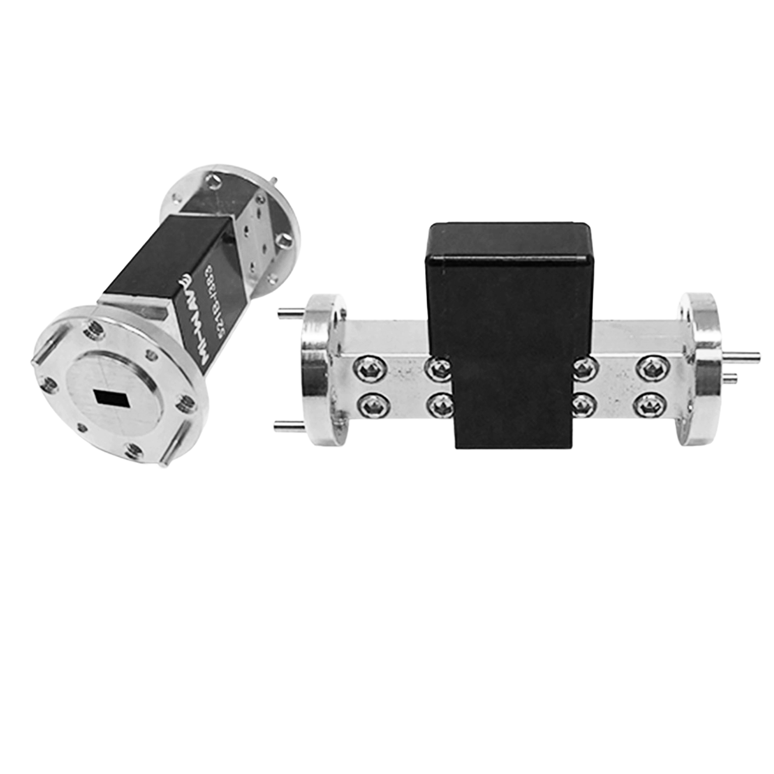
Mi-Wave Attenuators
Mi-Wave’s RF and Microwave Attenuators are precision-engineered components designed to provide accurate, repeatable control of signal power across microwave and millimeter-wave frequency bands. Available in a wide range of configurations including fixed, variable, voltage-controlled, and programmable attenuators, these solutions support applications from laboratory testing to deployed RF systems.
Covering frequencies from 8 GHz to 220 GHz and beyond, Mi-Wave attenuators are built for integration into waveguide and coaxial transmission systems, offering stable attenuation characteristics, low reflection, and dependable mechanical performance.
Whether used for signal level adjustment, system calibration, generator protection, or power measurement, Mi-Wave attenuators deliver consistent performance in demanding environments such as satellite communications, radar systems, electronic warfare, and RF test and measurement setups.
Each attenuator is designed with precision calibration and repeatability in mind, ensuring engineers can rely on accurate signal control across a wide range of operating conditions.
The standard models shown represent only part of Mi-Wave’s broader product capabilities. Custom configurations are available to support specific frequency bands, interfaces, and application requirements, enabling optimized solutions for specialized RF, microwave, and millimeter-wave systems.
Features & Specifications
Mi-Wave attenuators are engineered to provide precise, stable signal control across microwave and millimeter-wave systems.
Wide Frequency Coverage: 8 GHz to 220 GHz+
Supports standard microwave and mmWave bands, enabling use across a wide range of RF applications.
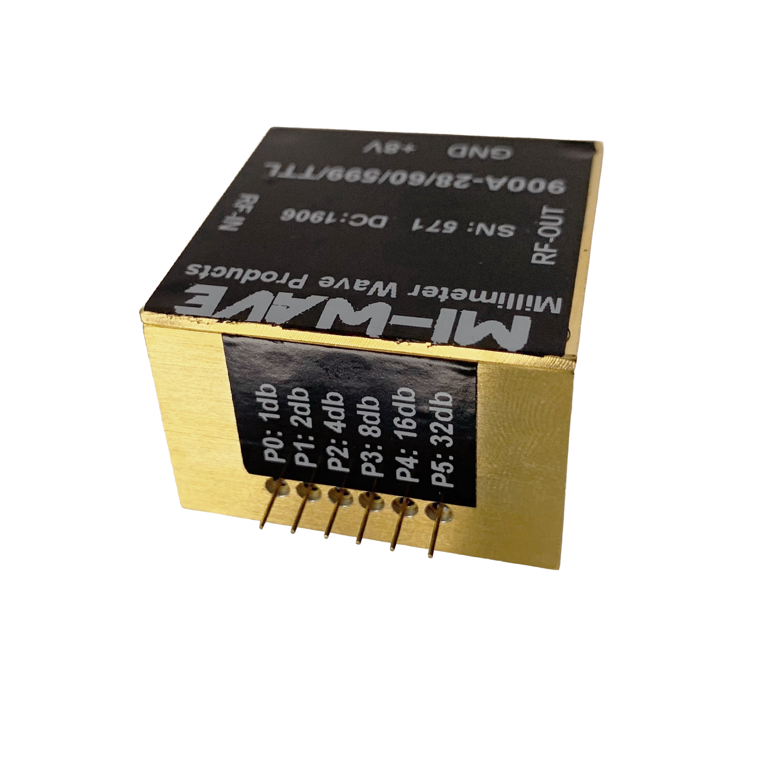
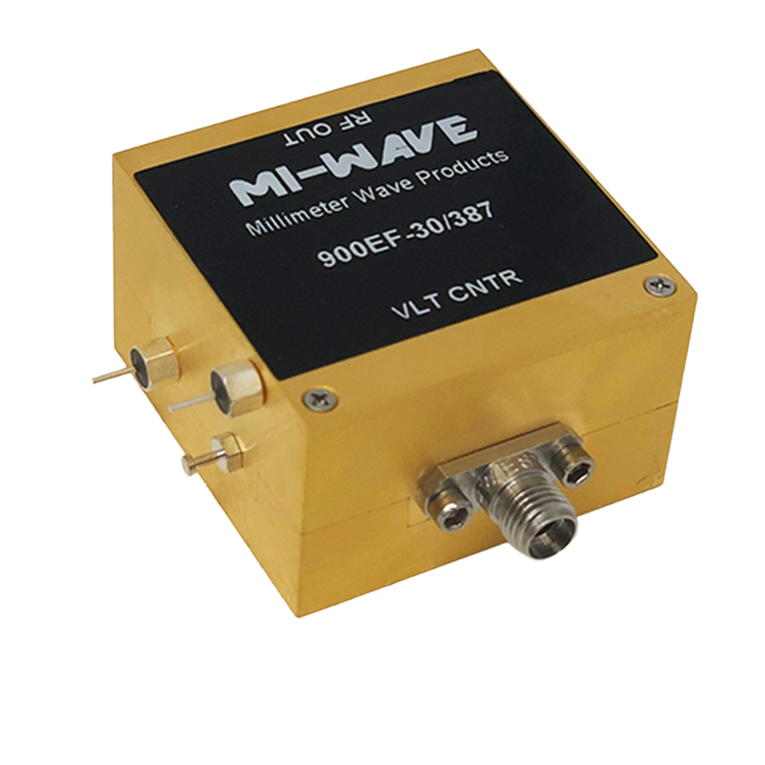
Multiple Attenuator Types Available
Includes fixed, variable, voltage-controlled, and programmable attenuators to meet diverse system requirements.
High Accuracy and Repeatability
Precision calibration ensures reliable attenuation levels with consistent performance over time.
Low Reflection and Stable RF Performance
Designed to minimize VSWR and maintain signal integrity within RF transmission systems.
Waveguide and Coaxial Configurations
Available in standard waveguide sizes and coaxial interfaces for flexible system integration.
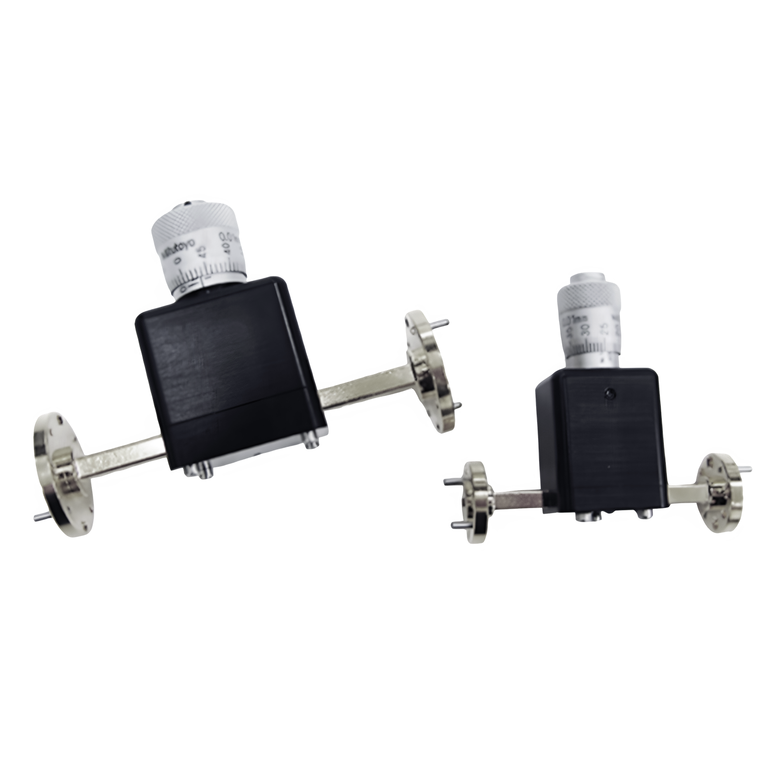
Manual and Electronic Control Options
Supports micrometer-driven, voltage-controlled, and digitally programmable attenuation methods.
Wide Attenuation Range
Available in standard attenuation values and adjustable ranges depending on the model.
Robust Mechanical Design
Engineered for durability and repeatable operation in laboratory and field environments.
Fast Response (Voltage-Controlled Models)
Supports rapid attenuation changes for AGC, ALC, and dynamic RF systems.
Calibration at Specified Frequency
Each unit can be calibrated at the exact operating frequency for precise measurement applications.
Suitable for High-Frequency Applications
Optimized for use in microwave and millimeter-wave systems, including Q, V, and W bands.
Applications
Mi-Wave attenuators are used across microwave and millimeter-wave systems where precise signal control, measurement accuracy, and system protection are required.
RF Test and Measurement
Used in laboratory environments to control signal levels for accurate testing of RF components, subsystems, and full system evaluations.
Signal Level Control
Provides precise reduction of RF power to ensure signals remain within optimal operating ranges for system performance.
Generator Protection
Helps isolate RF signal sources from mismatched loads, reducing reflections and protecting sensitive equipment.
Power Measurement Range Extension
Allows RF power meters and sensors to measure higher power signals safely by attenuating input levels.
Calibration and Verification Systems
Supports systems requiring known, repeatable attenuation values for calibration and reference measurements.
Automatic Gain and Level Control (AGC / ALC)
Voltage-controlled attenuators enable dynamic signal adjustment in real-time RF systems.
Microwave and Millimeter-Wave Communications
Used in communication systems to manage signal strength across frequency bands including Ka, Q, V, and W-band.
Radar and Electronic Warfare (EW)
Supports wideband and high-frequency systems requiring controlled signal levels and stable RF performance.
Waveguide Transmission Systems
Integrated into waveguide assemblies for controlled attenuation and improved system stability.
Research and Development (R&D)
Ideal for prototyping, experimentation, and development of RF and mmWave technologies.
Frequently Asked Questions (FAQ)
What is an RF attenuator?
An RF attenuator is a device used to reduce the power level of a signal without significantly distorting its waveform.
What types of attenuators does Mi-Wave offer?
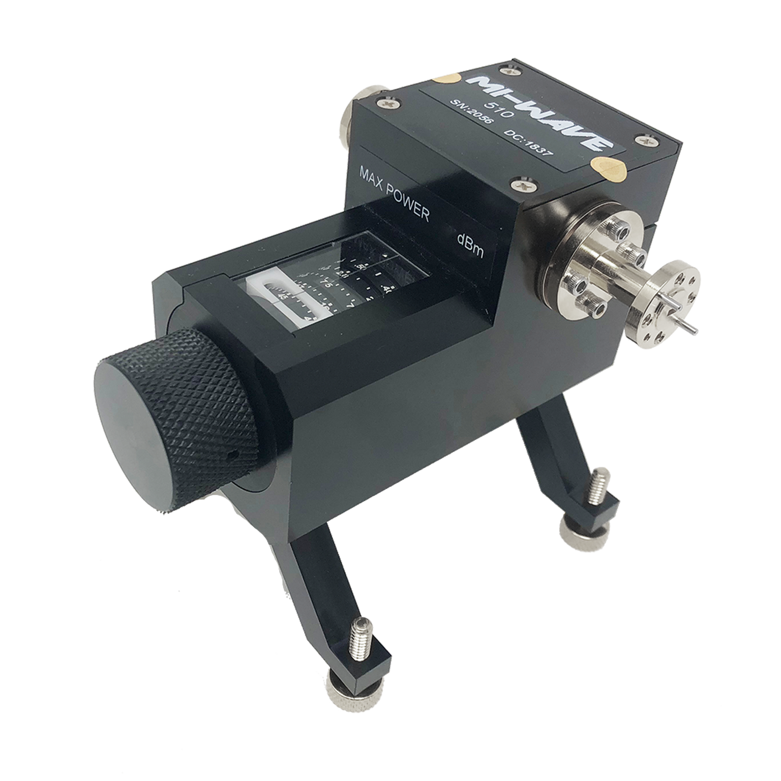
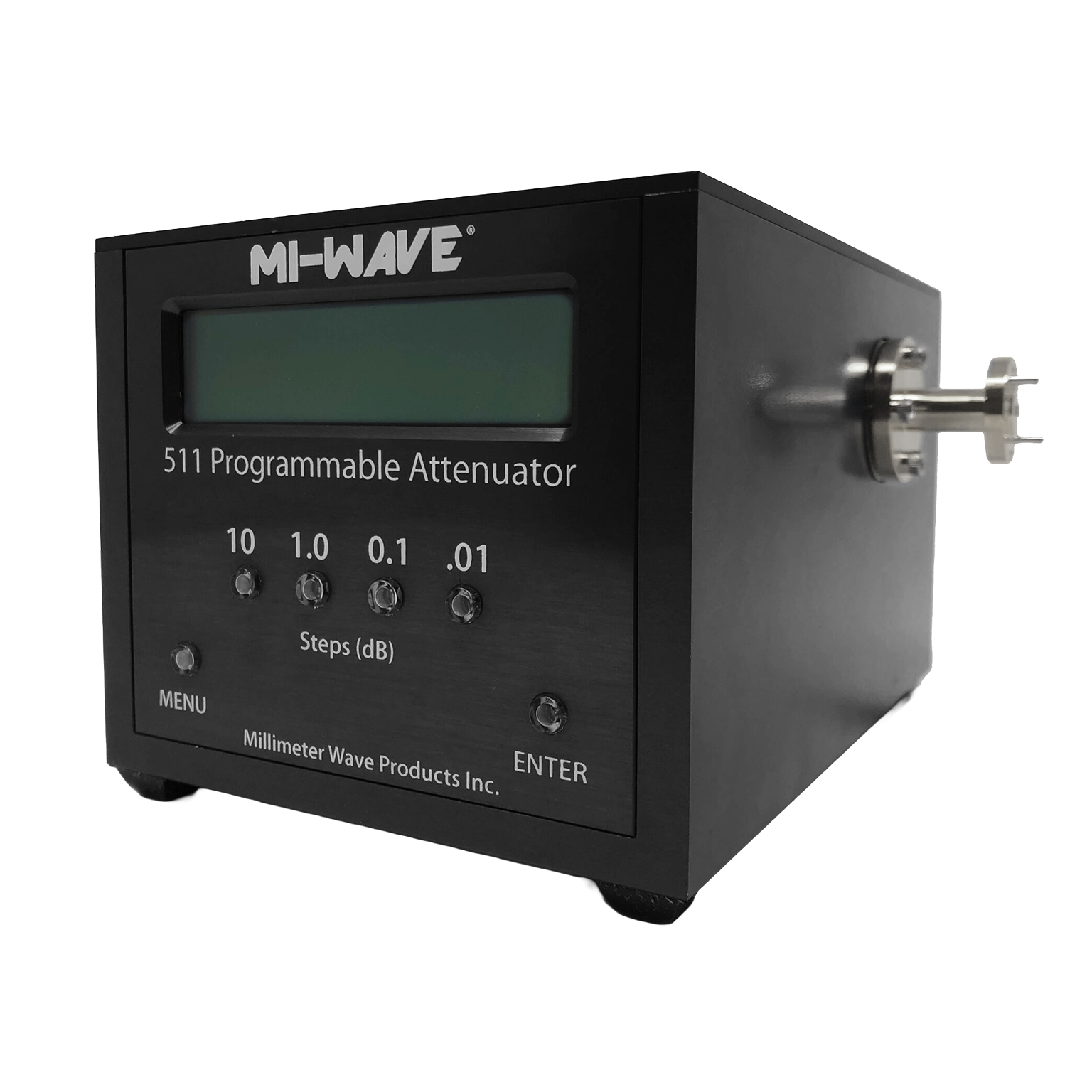
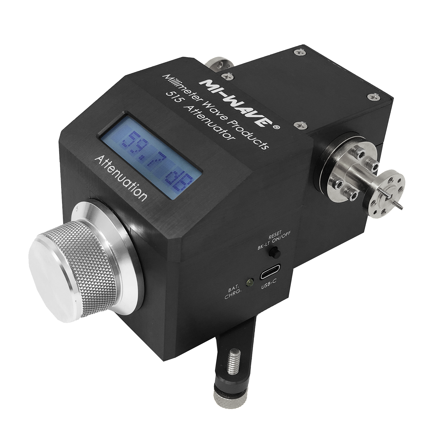
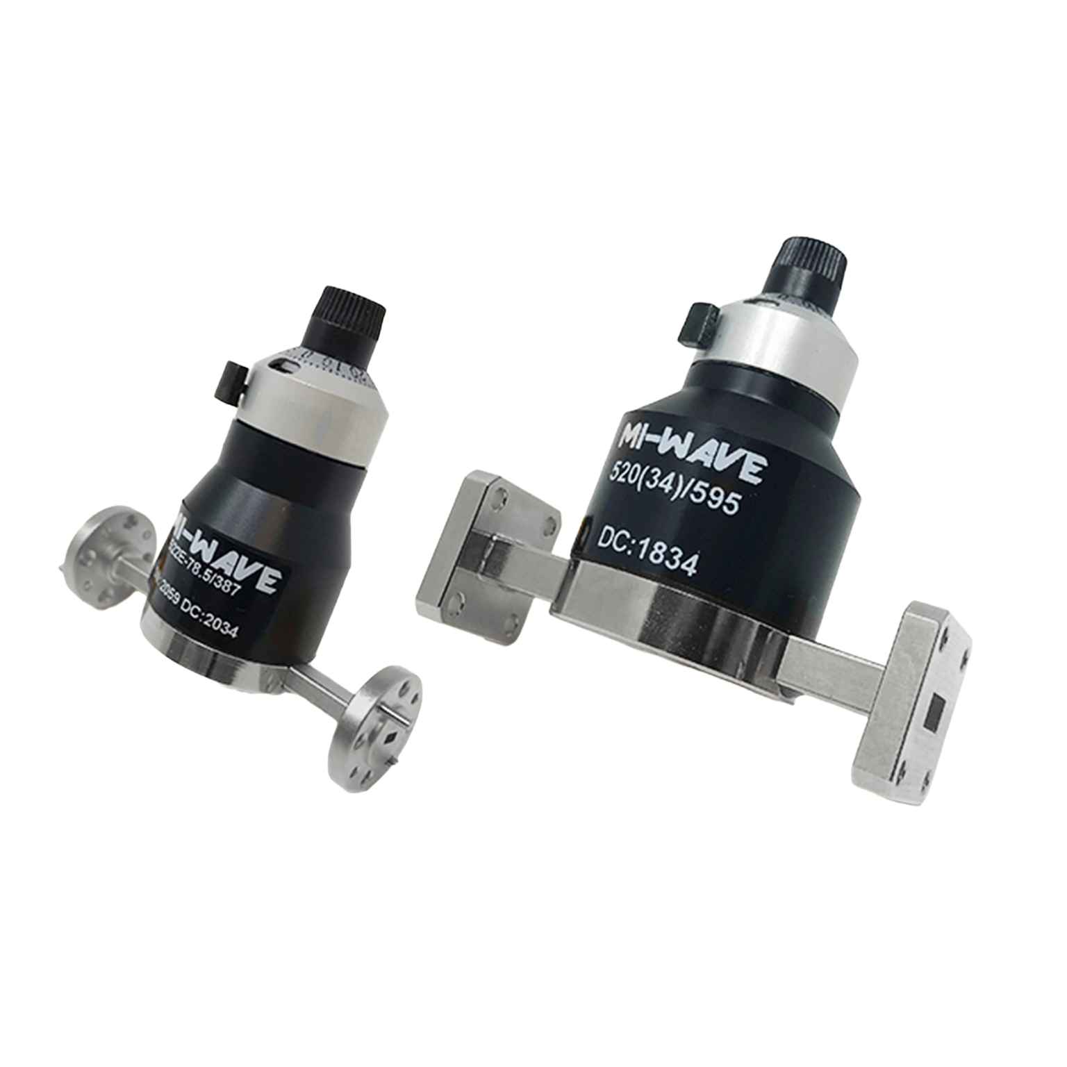
Mi-Wave offers fixed attenuators, micrometer-driven variable attenuators, voltage-controlled attenuators, and programmable attenuators for waveguide and coaxial systems.
What frequency ranges do Mi-Wave attenuators cover?
Mi-Wave attenuators typically cover frequencies from 8 GHz to 220 GHz, depending on the model and waveguide band.
What is the difference between fixed and variable attenuators?
- Fixed attenuators provide a constant level of attenuation
- Variable attenuators allow the attenuation level to be adjusted manually or electronically
What is attenuation measured in?
Attenuation is measured in decibels (dB), which represent the reduction in signal power.
What is an H-plane attenuator?
An H-plane attenuator is designed to introduce attenuation within the H-plane of a waveguide, providing stable and predictable RF performance.
Why are attenuators used in RF systems?
They are used for signal level control, protecting equipment, improving impedance matching, and enabling accurate measurements.
Can attenuators improve measurement accuracy?
Yes. Attenuators help stabilize signals and reduce reflections, which improves measurement reliability.
What is a voltage-controlled attenuator?
A voltage-controlled attenuator adjusts signal attenuation based on an applied control voltage, often used in AGC and ALC systems.
Are Mi-Wave attenuators suitable for millimeter-wave applications?
Yes. Mi-Wave attenuators are designed for both microwave and millimeter-wave frequency ranges, including high-frequency applications.
RF Attenuator Calculators
These RF attenuator calculators are designed to support microwave and millimeter-wave engineers working with direct reading precision attenuators, waveguide attenuators, and laboratory RF test setups. Use these tools to quickly convert attenuation values, estimate power levels, evaluate cascaded loss, and analyze impedance match performance for systems spanning X-Band through J-Band.
dB to Power Ratio
Convert attenuation or gain in decibels to a linear power ratio.
Power Ratio to dB
Convert a linear power ratio into decibels.
dBm to Watts
Convert RF power in dBm to watts for test and system-level calculations.
Watts to dBm
Convert watts to dBm for RF signal level analysis.
Cascaded Attenuation Calculator
Add multiple attenuator values together to determine total path attenuation.
VSWR to Return Loss
Estimate return loss from a known VSWR value.
Glossary of Attenuator Fundamentals
Attenuator
A passive or active RF component used to reduce the power level of a signal without significantly distorting its waveform.
Fixed Attenuator
An attenuator that provides a constant, non-adjustable level of signal reduction.
Variable Attenuator
An attenuator that allows the user to manually adjust the level of attenuation.
Voltage-Controlled Attenuator (VVA)
An attenuator where the attenuation level is controlled by an applied DC voltage, commonly used in automated RF systems.
Programmable Attenuator
An electronically controlled attenuator that can be adjusted digitally, often used in automated test systems.
Rotary Vane Attenuator
A precision mechanical attenuator that varies attenuation by rotating a resistive vane within a waveguide.
Micrometer-Driven Attenuator
A variable attenuator that uses a micrometer screw for fine, high-resolution attenuation control.
Electrical Performance
Attenuation (dB)
The reduction of signal power expressed in decibels.
Formula:
Attenuation (dB) = 10 × log₁₀(Pin / Pout)
Insertion Loss
The total signal loss introduced by a component, including both intended attenuation and additional losses.
Accuracy
The degree to which the actual attenuation matches the specified attenuation value.
Repeatability
The ability of an attenuator to return to the same attenuation value under identical conditions.
Resolution
The smallest change in attenuation that can be reliably adjusted or measured.
Linearity
The ability of the attenuator to reduce signal power proportionally without distortion.
Dynamic Range
The range between the minimum and maximum attenuation levels achievable by the device.
Flatness
The consistency of attenuation across a specified frequency range.
Return Loss
A measure of how much signal is reflected back toward the source due to impedance mismatch.
VSWR (Voltage Standing Wave Ratio)
A measure of impedance matching in RF systems. Lower VSWR indicates better matching and less reflection.
Isolation
The degree to which a component prevents signal leakage between ports or paths.
Power Handling
The maximum RF power an attenuator can safely dissipate without damage or performance degradation.
RF and Frequency Concepts
Radio Frequency (RF)
Electromagnetic signals used for communication, radar, and electronic systems.
Microwave Frequencies
Typically defined as frequencies between 1 GHz and 30 GHz.
Millimeter-Wave (mmWave)
Frequencies above 30 GHz, used in advanced communications, radar, and sensing systems.
Frequency Range
The span of frequencies over which an attenuator maintains specified performance.
Bandwidth
The width of the frequency range over which the attenuator operates effectively.
Center Frequency
The midpoint of a frequency range, often used as a reference for calibration.
Specified Frequency
The exact frequency at which an attenuator is calibrated for maximum accuracy.
Waveguide and Physical Design
Waveguide Attenuator
An attenuator designed for use in waveguide transmission systems, typically at microwave and mmWave frequencies.
Coaxial Attenuator
An attenuator designed for coaxial cable systems using connectors such as SMA, K, or 2.4 mm.
H-Plane Attenuator
An attenuator that introduces signal reduction in the H-plane of a rectangular waveguide.
E-Plane Attenuator
An attenuator that introduces signal reduction in the E-plane of a rectangular waveguide.
Waveguide Band
A standardized frequency range associated with a specific waveguide size (e.g., WR-28, WR-22).
Flange
The mechanical interface used to connect waveguide components together.
Impedance Matching
The process of ensuring maximum power transfer between components by minimizing reflections.
Control and Operation
Manual Control
Adjustment of attenuation using physical mechanisms such as knobs, micrometers, or rotary vanes.
Electronic Control
Adjustment of attenuation using electrical signals, such as voltage or digital commands.
Control Voltage
The DC voltage used to adjust attenuation in voltage-controlled attenuators.
Step Attenuation
Discrete attenuation levels in programmable or digital attenuators.
Continuous Attenuation
Smooth, uninterrupted adjustment of attenuation levels.
System Applications
Signal Level Control
Adjusting RF signal power to meet system requirements or prevent overload.
Generator Protection
Reducing reflected power to protect RF signal sources from damage.
Load Mismatch
A condition where impedance differences cause reflections and signal degradation.
Power Measurement Extension
Using attenuation to allow measurement devices to handle higher input power levels safely.
Calibration
The process of verifying and adjusting system performance against known standards.
Automatic Gain Control (AGC)
A system that automatically adjusts signal levels to maintain consistent output.
Automatic Level Control (ALC)
A system that maintains a constant RF output level by adjusting gain or attenuation.
Test and Measurement Systems
Laboratory setups used to evaluate RF components and system performance.
Electronic Warfare (EW)
Systems that operate across wide frequency ranges for signal detection, jamming, and countermeasures.
Satellite Communications (SatCom)
High-frequency communication systems used for data transmission via satellites.
Advanced / High-Frequency Considerations
mmWave Attenuation
Signal reduction at millimeter-wave frequencies, where precision and mechanical stability are critical.
Thermal Stability
The ability of an attenuator to maintain consistent performance across temperature variations.
Phase Stability
The ability to maintain consistent signal phase while attenuating amplitude.
Parasitic Effects
Unwanted electrical effects such as capacitance or inductance that can impact high-frequency performance.
Skin Effect
The tendency of RF current to flow near the surface of conductors at high frequencies, affecting loss.