
How To Specify Antennas
This guide contains information on a representative group of millimeter wave antennas and feeds that are currently available from Millimeter Wave. The design capability that indicated may also be used to solve other unique requirements in the antenna field. Inquiries outlining special require s for millimeter antennas, antenna feeds and complete antenna systems are cordially invited
Email inquiries to engineering@miwv.com
How To Specify Antennas
The selection of the correct millimeter antenna for use in radar or communications system is one of the most important choices in specifying a millimeter wave system. A properly selected and designed antenna will pay dividends in improved system capability, operation, and reliability.
Mi-Wave specializes in advanced antenna design that coves the frequency spectrum from 12 through 220 GHz. Our experience has led to techniques yielding superior performance and reliability. These antennas are currently being used in space and ground installations throughout the world.
This guide contains information on a representative group of millimeter wave antennas and
feeds that are currently available from Millimeter Wave. The design capability that indicated may also be used to solve other unique requirements in the antenna field. Inquiries outlining special require s for millimeter antennas, antenna feeds and complete antenna systems are cordially invited.
Lets Begin
- The primary information required in the selection of an antenna is the operating frequency and frequency
- The next parameter to be determined is the effective antenna
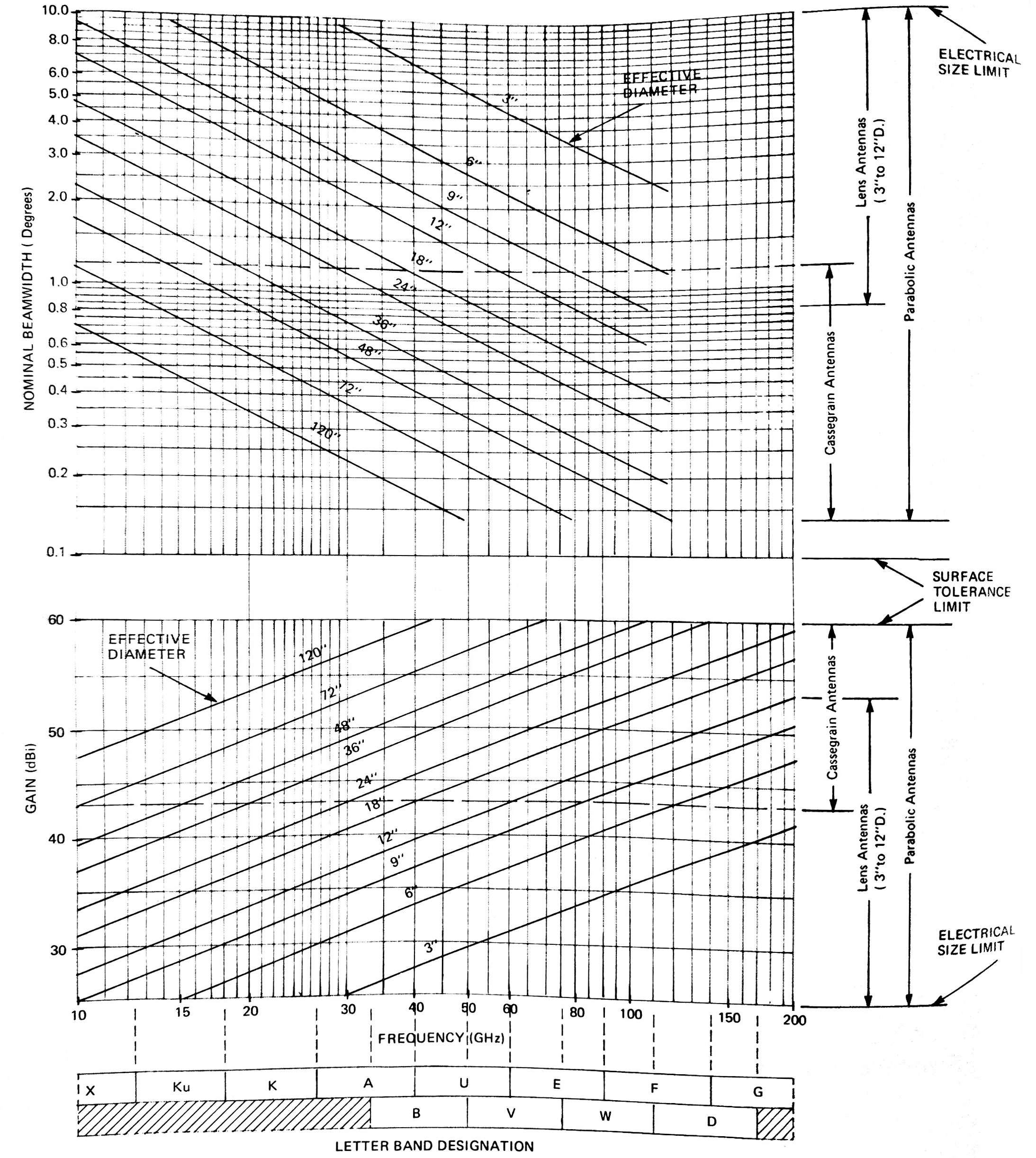
- Based upon the frequency and effective antenna diameter, the antenna gain and beamwidth are determined using the beamwidth and gain selection charts
- With the antenna beamwidth or gain known, the beamwidth and gain selection charts can be used to determine the effective antenna diameter for a desired frequency. (The beamwidth and gain selection charts relate beamwidth, gain and effective antenna diameter for any given frequency. When one of these values and the frequency are known, the remaining two values can be found with the It should be noted that these lines indicate standard available antenna diameters. Sizes between the standard diameters, although available, will have nonrecurring engineering and additional delivery time associated with their purchase. Whenever possible, the indicated solid standard diameter should be specified, e.g., 3-, 6-, 12-, 18-inches, etc.)
- After frequency, effective antenna diameter, beamwidth and gain have been determined, refer to the Antenna Selection Table for the appropriate antenna type and range of sidelobe Two examples of antenna selection are included herein. This completes the specification of a millimeter antenna. There are, of course, mechanical considerations, such as wind loading, that are best chosen during technical discussions with Mi-Wave engineering staff.
Beamwidth and Gain Selection Chart
| Antenna Type | Gain Range (1) | Beamwidth Range (2) | Sidelobe Range Nominal | Application | View Collection |
|---|---|---|---|---|---|
| Parabolic Reflectors with Prime Focus Feeds Series 202/203 | 26 dBi to 57 dBi | 0.18° to 6.5° | -18 dB to -25dB | General Purpose, Radars, Receivers | |
| Cassegrain Antennas Series 222/823 | 29 dBi to 58 dBi | 0.18° to 4.5° | -16 dB to -22dB | Medium Profile, Compact Low Waveguide Transmissions Loss Radiometers, Radars | |
| Horn Lens Antennas Series 258 | 26 dBi to 45 dBi | 0.8° to 6.5° | -18 dB to -30 dB | Low Sidelobes and Backlobes No Aperture Blockage Radiometers, Receivers | |
| Horn Antennas (Scalar Feeds) Series 268 | 15 dBi | 22° to 26° | -12 dB to -25 dB | Broad Beamwidth, High Efficiency Low Sidelobes and Backlobes |