
The Mi-Wave WR-22 wideband waveguide diplexer is a precision passive component designed to separate and combine uplink (TX) and downlink (RX) signals in advanced satellite communication systems. This waveguide diplexer covers 37.5–42.5 GHz (downlink) and 47–52 GHz (uplink) with 1.2 dB typical insertion loss and 60 dBc channel rejection, enabling clean TX/RX separation in compact RF front ends, antenna feed systems, and Satcom transceiver chains.
A waveguide diplexer is a passive frequency-selective device that allows two different frequency bands to share a single transmission path while maintaining isolation between them. Mi-Wave’s WR-22 wideband waveguide diplexer is a precision example of this technology, designed to separate and combine uplink (TX) and downlink (RX) signals in advanced satellite communication systems. This waveguide diplexer covers 37.5–42.5 GHz (downlink) and 47–52 GHz (uplink) with 1.2 dB typical insertion loss and 60 dBc channel rejection, enabling clean TX/RX separation in compact RF front ends, antenna feed systems, and Satcom transceiver chains.
Covering 37.5–42.5 GHz (downlink) and 47–52 GHz (uplink), the WR-22 diplexer supports modern high-throughput Satcom architectures that require wide bandwidth, clean spectral separation, and stable system performance. Its compact waveguide implementation allows seamless integration into RF front ends, antenna feed systems, and transceiver chains.
With 1.2 dB typical insertion loss in both bands and 60 dBc typical rejection between channels, this diplexer minimizes signal degradation while preventing leakage and self-interference. The result is improved system efficiency, enhanced signal integrity, and reliable operation in demanding microwave and millimeter-wave environments.
The standard models shown represent only part of Mi-Wave’s broader product capabilities. Custom configurations are available to support specific frequency bands, interfaces, and application requirements, enabling optimized solutions for specialized RF, microwave, and millimeter-wave systems.
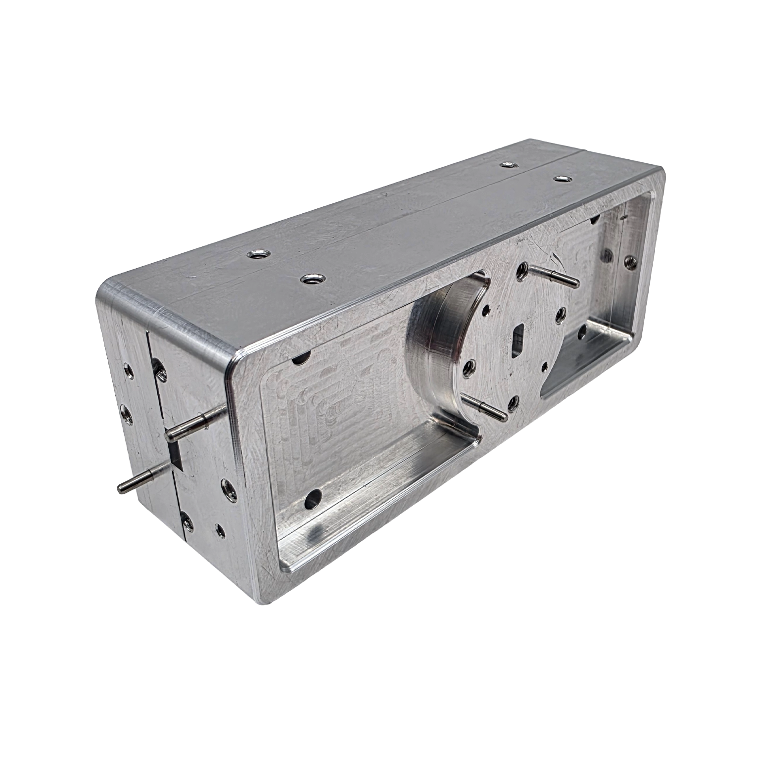
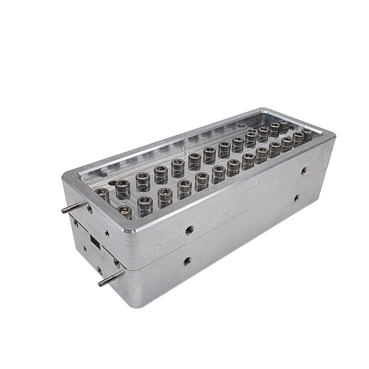
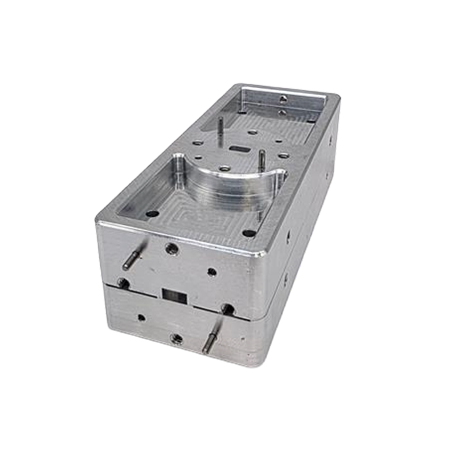
*Actual product may be different from the image shown per customers specifcations
*All data presented is collected from a sample lot.
* Actual data may vary unit to unit, slightly.
*All testing was performed under +25 °C case temperature.
*Consult factory to confirm if material, plating, size, shape, orientation and any electrical parameter is critical for the application as website information is for reference only.
*Millimeter Wave Products, Inc. reserves the right to change the information presented on website without notice as we continue to enhance the performance and design of our products.
Key Specifications
Waveguide Size: WR-22
Frequency Range: 33 GHz to 55 GHz
Insertion Loss: 0.75 dB (typical)
Isolation: 40 dB (typical)
Polarization: Dual orthogonal (horizontal/vertical or linear pairs)
Configuration: Waveguide input with dual orthogonal outputs
Low Insertion Loss
1.2 dB typical in both bands to preserve system gain and minimize impact on noise figure and EIRP.
High Channel Rejection
60 dBc typical rejection between bands to suppress unwanted energy and prevent cross-channel interference.
High Isolation Between TX and RX Paths
Improves signal integrity and reduces risk of self-interference in full-duplex systems.
Compact Waveguide Design (WR-22)
Optimized for integration into space-constrained Satcom front ends and antenna systems.
Broadband mmWave Performance
Designed to support high-capacity, wideband communication links.
How It Works
A diplexer is a passive frequency-selective network that allows two different frequency bands to share a single transmission path while maintaining isolation between them. In the WR-22 Wideband Diplexer, this is achieved using precision waveguide bandpass filtering structures that route signals based on frequency.
Frequency Separation Mechanism
The diplexer consists of two primary paths:
- Low-Side Path (Downlink / Receive): 37.5–42.5 GHz
- High-Side Path (Uplink / Transmit): 47–52 GHz
Each path includes a bandpass filter tuned to its specific frequency range.
- Signals within the low-side band pass through the RX path with minimal loss
- Signals within the high-side band pass through the TX path
- Signals outside each band are strongly attenuated (rejected)
This ensures that each frequency band is directed to the correct port while unwanted signals are suppressed.
Signal Routing Behavior
When both bands are present at the common port:
- The receive band is routed to the RX port
- The transmit band is routed to the TX port
- Each path sees high attenuation from the opposite band
This allows simultaneous transmit and receive operation using a shared waveguide interface without interference.
Isolation and Rejection
Isolation between TX and RX paths is achieved through:
- High-Q waveguide filter structures
- Careful spacing between passbands (guard band)
- Precision impedance matching
With 60 dBc typical rejection, the diplexer minimizes:
- TX leakage into the RX chain
- Receiver desensitization
- Spurious signal coupling
System Integration
The diplexer is typically placed at the RF front end, where it connects:
- A shared antenna or waveguide port
- A transmit chain (power amplifier path)
- A receive chain (low noise amplifier path)
This enables:
- Full-duplex operation
- Reduced component count
- Compact system architecture
Why This Matters
Without a diplexer, systems would require:
- Separate antennas
- Additional switching hardware
- More complex routing
The diplexer simplifies design while improving:
- Signal integrity
- Isolation
- System efficiency
Why It Matters for Satcom
Modern satellite communication systems rely on clean separation between transmit and receive paths to maintain performance and prevent interference. The WR-22 Wideband Diplexer directly supports this by:
- Improving TX/RX isolation for cleaner signal paths
- Reducing self-interference in full-duplex systems
- Preserving system noise figure through low insertion loss
- Maintaining EIRP performance on the transmit side
- Supporting wideband, high-throughput architectures
- Simplifying RF front-end design by combining filtering and routing
This makes it an essential component in systems where spectral efficiency, reliability, and compact integration are critical.
Applications
Satellite Communication Systems (Satcom)
Separates uplink and downlink signals in ground stations, gateways, and satellite payloads.
RF Front Ends
Integrates into transmit/receive chains to enable clean signal routing and filtering.
Antenna Feed Systems
Used with OMTs and feed horns to support dual-polarized, dual-band operation.
High-Throughput Satellites (HTS)
Supports wideband channels required for modern high-capacity communication systems.
Microwave & mmWave Transceivers
Improves isolation between transmit and receive paths in compact RF architectures.
Test & Measurement Systems
Used in lab environments for band separation and controlled RF signal routing.
Frequently Asked Questions (FAQ)
What is a diplexer?
A diplexer is an RF component that separates or combines signals from two different frequency bands into a single transmission path.
How is a diplexer different from a duplexer?
A diplexer separates signals by frequency bands, while a duplexer typically allows simultaneous transmit and receive at closely spaced frequencies using isolation techniques.
Why is high rejection important?
High rejection (60 dBc) ensures minimal leakage between transmit and receive bands, reducing interference and improving system performance.
How does insertion loss affect performance?
Lower insertion loss helps maintain signal strength, preserving both receiver sensitivity and transmit power.
Where is this diplexer typically used?
It is commonly used in Satcom ground stations, payloads, antenna feeds, and RF front-end systems.
Can this diplexer handle wideband signals?
Yes, it is specifically designed for wideband mmWave operation, supporting modern high-throughput communication systems.
Diplexer & RF Front-End Calculators
These calculators help evaluate diplexer performance in Satcom and RF systems, including guard band spacing, TX leakage into the RX path, insertion loss impact, interference margin at the receiver, and EIRP through the transmit chain.
Guard Band Calculator
Determines frequency separation between receive and transmit bands to evaluate isolation margin.
TX Leakage into RX
Estimates transmit signal leakage into the receive chain based on diplexer rejection.
Insertion Loss Impact
Calculates output power after diplexer insertion loss in the signal path.
Leakage Interference Margin
Compares TX leakage at the receiver input against the receiver noise floor or desired threshold.
EIRP Calculator
Estimates effective isotropic radiated power after diplexer loss, cable loss, and antenna gain.
Diplexer & Filtering Fundamentals
Diplexer
A passive RF device that separates or combines signals from two distinct frequency bands.
Bandpass Filter
A filter that allows a specific frequency range to pass while rejecting frequencies outside that range.
Passband
The frequency range where signals experience minimal attenuation.
Stopband
The frequency range where signals are strongly attenuated.
Guard Band
The frequency gap between passbands that helps improve isolation and prevent overlap.
Center Frequency
The midpoint of a passband.
Bandwidth
The width of the frequency range that a filter or diplexer supports.
RF Performance Metrics
Insertion Loss (IL)
Signal power lost when passing through a device.
Return Loss (RL)
The amount of reflected signal due to impedance mismatch.
VSWR (Voltage Standing Wave Ratio)
A measure of impedance matching efficiency.
Rejection
The level of attenuation applied to unwanted frequencies outside the passband.
Isolation
The degree of separation between two signal paths.
Channel Isolation
Isolation specifically between transmit and receive frequency bands.
Leakage
Unwanted signal energy that passes into the wrong signal path.
Dynamic Range
The range of signal levels a system can handle without distortion or loss.
System-Level Concepts
TX (Transmit Band)
The frequency band used to transmit signals.
RX (Receive Band)
The frequency band used to receive signals.
Full-Duplex Operation
Simultaneous transmission and reception of signals.
Self-Interference
Interference caused when transmit signals leak into the receive path.
EIRP (Effective Isotropic Radiated Power)
The effective transmitted power considering gain and losses.
Noise Figure (NF)
A measure of noise introduced by a component, especially important in receive paths.
Receiver Desensitization
Loss of receiver sensitivity due to strong interfering signals.
Waveguide & Hardware Concepts
Waveguide Diplexer
A diplexer implemented in waveguide form for low-loss mmWave operation.
WR-22 Waveguide
A standard waveguide supporting approximately 33–55 GHz frequencies.
Common Port
The shared input/output port where both frequency bands are combined.
TX Port
The port dedicated to the transmit frequency band.
RX Port
The port dedicated to the receive frequency band.
Flange Interface
The mechanical connection used to join waveguide components.
Advanced RF Behavior
Spurious Signals (Spurs)
Unwanted frequencies generated by nonlinearities or leakage.
Harmonics
Multiples of a fundamental frequency that can interfere with system performance.
Frequency Selectivity
The ability of a device to distinguish between desired and undesired frequencies.
Group Delay
The time delay variation of a signal across frequency.
Phase Linearity
Consistency of phase response across the passband.
Thermal Stability
The ability of a component to maintain performance across temperature variations.
High-Q Filtering
Filtering with sharp transitions between passband and stopband, enabling strong rejection.