
Description
Mi-Wave RF upconverters and downconverters provide high-performance frequency conversion solutions for microwave and millimeter-wave receiver systems. The 970A-39.65/599 Ka-Band Downconverter is engineered to translate high-frequency Ka-band RF signals from 39.4 to 39.9 GHz to a lower intermediate frequency, supporting receiver architectures where low noise figure, gain stability, and spectral integrity are critical.
Operating with a 500 MHz RF bandwidth, the 970A-39.65/599 downconverts incoming Ka-band signals to a standard IF output of 950 to 1450 MHz, enabling seamless integration with common receivers, demodulators, and signal processing hardware. Its internal local oscillator architecture provides stable frequency conversion across the operating band, simplifying system design and minimizing external synchronization requirements.
The downconverter is optimized for low-noise receiver front ends, offering a low single-sideband noise figure and high, stable conversion gain. This performance supports high-sensitivity systems where preserving weak signal content is essential. Internal filtering provides image suppression, while controlled gain stability ensures consistent performance across temperature and operating conditions.
Designed for professional RF systems, the 970A-39.65/599 features a WR-28 waveguide RF input and N-type IF output, supporting standard Ka-band front ends and L-band processing chains. The unit operates from a DC bias supply and is suitable for integration into laboratory environments, ground-based infrastructure, and fixed receiver installations.
Mi-Wave Ka-band downconverter platforms are used in advanced communication, sensing, and scientific applications where receiver sensitivity, frequency stability, and long-term reliability are essential.
Watch our informational video to learn more about this product family, including its key features, operating principles, and common applications.
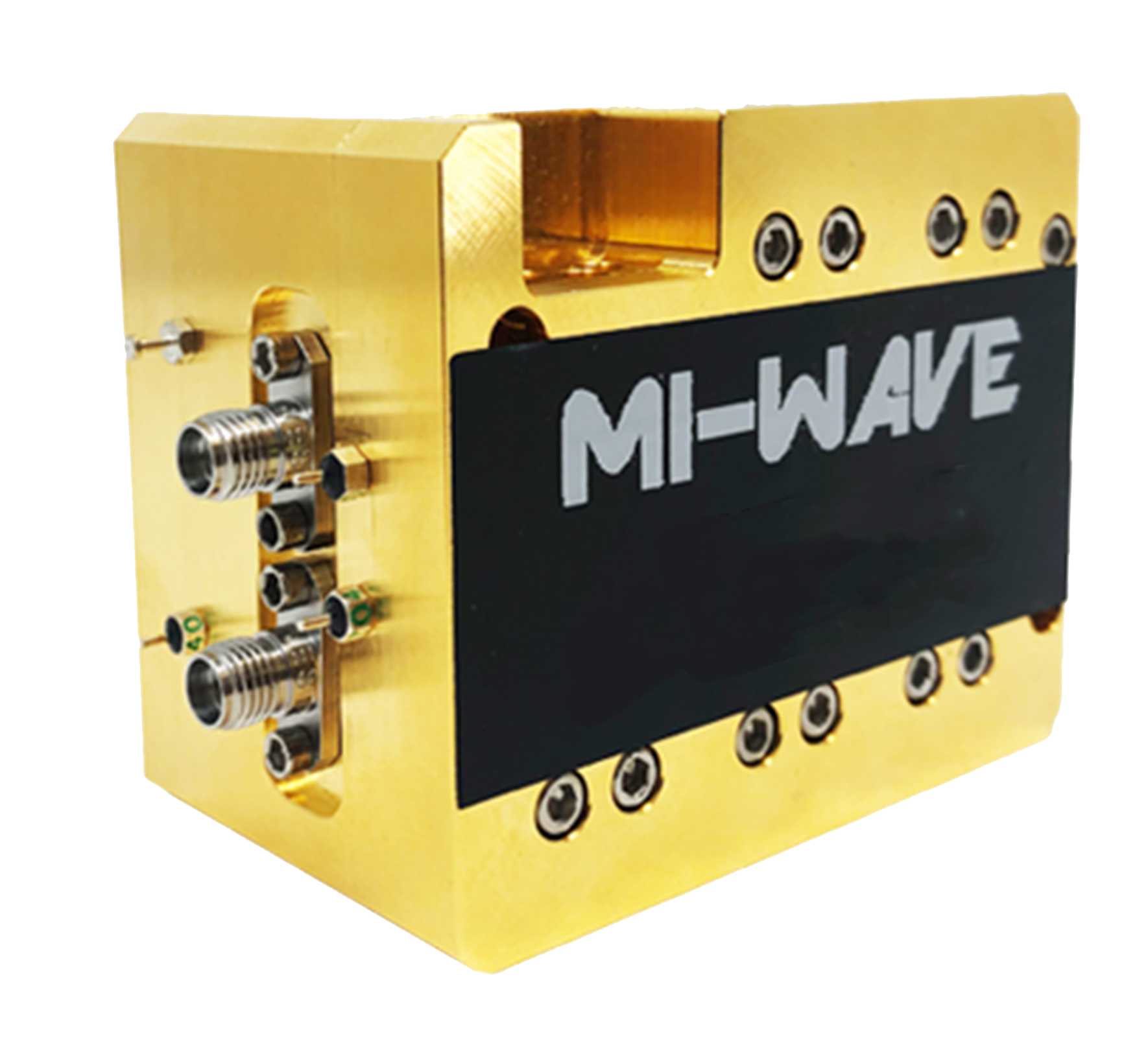
*Actual product may be different from the image shown per customers specifcations
*All data presented is collected from a sample lot.
* Actual data may vary unit to unit, slightly.
*All testing was performed under +25 °C case temperature.
*Consult factory to confirm if material, plating, size, shape, orientation and any electrical parameter is critical for the application as website information is for reference only.
*Millimeter Wave Products, Inc. reserves the right to change the information presented on website without notice as we continue to enhance the performance and design of our products.
Key Features & Performance Benefits
Low Phase Noise
Ultra-low phase noise local oscillators preserve signal integrity during frequency translation. This is critical for high-order modulation schemes, narrowband carriers, and systems where EVM, BER, and spectral purity are tightly specified.
Excellent Frequency Stability
High-stability reference options support long-term accuracy and repeatability across temperature and environmental changes. Ideal for satellite ground equipment, precision measurement systems, and synchronized multi-channel architectures.
Superfine Tuning Steps
Fine frequency resolution allows precise channel placement and easy alignment within crowded spectra. This capability is especially valuable for lab testing, interference mitigation, and dynamic frequency planning.
Multichannel Options Available
Multi-channel upconversion and downconversion configurations reduce system complexity and footprint while supporting parallel signal paths. Well suited for MIMO systems, phased arrays, and multi-carrier SatCom terminals.
Gain Control Options Available
Integrated gain control enables level optimization across varying input powers and link conditions. This helps prevent compression, improves dynamic range, and simplifies system calibration.
Low LO Leakage
Careful RF and LO isolation minimizes spurious emissions and unwanted leakage, improving spectral compliance and reducing interference in dense RF environments.
High Image Rejection
Advanced filtering and conversion techniques deliver strong image suppression, ensuring clean output spectra and improved receiver sensitivity.
Small, Compact Packages
Space-efficient designs support tight installations in racks, shelters, airborne platforms, and outdoor enclosures without sacrificing performance.
RF Upconverter & RF Downconverter Overview
Mi-Wave designs and manufactures high-performance RF upconverters and RF downconverters for precision frequency translation across X-Band (8–12 GHz), Ku-Band (12–18 GHz), Ka-Band (26–40 GHz), Q-Band (33–50 GHz), V-Band (50–75 GHz), W-Band (75–110 GHz), and frequencies beyond 110 GHz. Our portfolio includes microwave frequency converters, millimeter-wave converters, Block Upconverters (BUCs), Low Noise Block Downconverters (LNBs), wideband converters, and custom RF frequency conversion solutions for satellite communications (SatCom), radar, telemetry, electronic warfare (EW), wireless communications, and RF test & measurement systems.
RF upconverters and RF downconverters are fundamental components in modern RF systems. Their primary function is frequency translation, shifting signals between Radio Frequency (RF) and Intermediate Frequency (IF) using a stable Local Oscillator (LO). Downconverters translate high-frequency RF signals into lower IF frequencies for easier processing, while upconverters convert IF signals back into RF for transmission. These converters enable complex communication, sensing, and measurement systems to operate efficiently while maintaining excellent signal integrity.
In transmit architectures, an RF upconverter is often paired with a power amplifier to form a Block Upconverter (BUC), while receiver systems commonly combine a downconverter with a Low Noise Amplifier (LNA) to create a Low Noise Block Downconverter (LNB). Mi-Wave frequency converters are engineered for low phase noise, excellent frequency stability, high image rejection, low LO leakage, predictable gain, and reliable operation in laboratory, commercial, aerospace, and defense environments.
RF Frequency Conversion Signal Flow
RF Upconverter
RF Downconverter
Signal Input
An RF or IF signal enters the frequency converter while a Local Oscillator provides the reference frequency required for frequency translation.
Frequency Translation
Internal mixer stages combine the signal and LO to generate the desired sum or difference frequency while minimizing unwanted mixing products.
Signal Conditioning
Internal filtering and amplification help reduce spurious responses, improve image rejection, maintain gain, and preserve spectral purity.
System Integration
The converted signal is delivered to transmitters, receivers, radar systems, satellite communication equipment, RF instrumentation, or digital processing platforms.
Applications for RF Upconverters, RF Downconverters & RF Signal Conversion Solutions
RF upconverters, RF downconverters, LNBs, BUCs, and frequency conversion solutions are designed for integration into a wide range of RF, microwave, and millimeter-wave systems where accurate frequency translation, spectral purity, and long-term stability are critical. These products are widely deployed across commercial, industrial, scientific, and defense-grade platforms, supporting fixed, mobile, airborne, and outdoor installations.
Satellite Communication
RF signal conversion products are core building blocks in satellite uplink and downlink architectures, enabling reliable translation between IF and high-frequency RF bands.
Typical satellite communication applications include:
-
Ground-based satellite terminals and gateway stations
-
Teleports and network operation centers
-
VSAT and transportable SatCom terminals
-
Ku-, Ka-, Q-, and V-band uplink and downlink systems
-
Integration with BUCs, LNBs, LNAs, and modems
-
Payload testing and frequency planning support
These solutions help maintain clean spectra, reduce phase noise, and ensure stable links in crowded satellite frequency allocations.
Point-to-Point Radio Communication
RF upconverters and downconverters are commonly used in high-capacity point-to-point radio links for telecom, private networks, and critical infrastructure.
Common use cases include:
-
Microwave and millimeter-wave backhaul links
-
Fixed wireless access and private radio networks
-
High-throughput data transport between sites
-
Urban and rural point-to-point connectivity
-
Spectrum-efficient, narrow-channel radio systems
Precise frequency translation and high image rejection help maximize link reliability and spectral efficiency.
Radar Communication and Radar Systems
In radar communication and sensing platforms, frequency converters play a critical role in signal generation and receiver processing.
Typical radar applications include:
-
Surveillance and tracking radar systems
-
Weather and meteorological radar
-
FMCW and pulse-Doppler radar architectures
-
Ground-based, airborne, and maritime radar platforms
-
Receiver front-end frequency translation and filtering
-
Clean local oscillator distribution for radar transmit chains
Low phase noise and excellent frequency stability improve range resolution, Doppler accuracy, and target discrimination.
Meteorology and Atmospheric Sensing
RF signal conversion solutions are widely used in meteorological and environmental monitoring systems that rely on radar and remote sensing techniques.
Applications include:
-
Weather radar for precipitation and storm tracking
-
Atmospheric profiling and cloud monitoring
-
Climate research and environmental observation systems
-
Doppler radar signal processing chains
-
Long-duration outdoor monitoring installations
Stable frequency performance ensures accurate data collection under varying environmental conditions.
Telemetry
Telemetry systems depend on reliable RF frequency translation to transmit real-time data from remote or mobile platforms.
Common telemetry applications include:
-
Aerospace and flight testing telemetry
-
Defense and range instrumentation
-
Automotive and motorsports testing
-
Industrial monitoring and remote sensing
-
UAV and unmanned platform data links
Low LO leakage and precise tuning support accurate data recovery in dynamic operating environments.
5G and Millimeter-Wave Wireless
RF upconverters and downconverters support development, testing, and deployment of 5G and emerging mmWave wireless technologies.
Typical applications include:
-
5G FR2 base station and small cell testing
-
Beamforming and MIMO system validation
-
mmWave signal generation and analysis
-
Wireless backhaul and access research platforms
-
Prototype and pre-deployment verification systems
Fine tuning resolution and multi-channel options enable flexible system architectures for next-generation wireless networks.
Astronomy and Scientific Research
In radio astronomy and scientific instrumentation, RF signal conversion solutions enable detection and processing of extremely weak signals.
Applications include:
-
Radio astronomy observatories and receiver chains
-
Space science and deep-space signal monitoring
-
University and government research laboratories
-
Spectral analysis and long-duration observations
-
Precision frequency translation for low-noise receivers
Exceptional frequency stability and low phase noise are essential for high-sensitivity scientific measurements.
RF Test, Measurement, and System Integration
Across all industries, RF upconverters and downconverters are widely used in laboratory, production, and system integration environments.
Typical uses include:
-
RF and mmWave test benches
-
Signal generators and receiver test setups
-
Automated test equipment and calibration systems
-
Device characterization and validation
-
System-level integration and troubleshooting
These solutions provide reliable, repeatable performance for both R&D and manufacturing workflows.
System Performance and Signal Integrity Benefits
Across all applications, RF signal conversion solutions help:
-
Maintain spectral purity and signal integrity
-
Reduce spurious responses and image products
-
Improve system dynamic range
-
Support stable, repeatable frequency translation
-
Enable scalable and modular RF architectures
RF upconverters, RF downconverters, LNBs, BUCs, and frequency converters serve as foundational components in modern RF, microwave, and millimeter-wave systems where performance and reliability are essential.
RF Upconverter and Downconverter FAQ
These quick answers cover RF upconverters, RF downconverters, BUCs, LNBs, and frequency conversion specs used in satellite communications (SatCom), point-to-point microwave links, radar, telemetry, test and measurement, and 5G/mmWave systems.
Quick Answers
What does an RF upconverter do?
An RF upconverter translates a lower-frequency signal, such as IF or L-band, to a higher RF or microwave frequency so it can be transmitted by an antenna. In many transmit chains, the upconverter is followed by an RF power amplifier; when integrated, it is often called a Block Upconverter (BUC).
What does an RF downconverter do?
An RF downconverter converts a high-frequency RF input to a lower intermediate frequency (IF) that is easier to filter, amplify, digitize, and demodulate. In receiver front ends, a downconverter is often paired with an LNA; when integrated, it is commonly called an LNB (Low-Noise Block downconverter).
What is the difference between a BUC and an RF upconverter?
A BUC combines an RF upconverter with an integrated power amplifier to deliver higher output power for satellite uplinks and other transmit applications. An RF upconverter alone performs frequency translation but may not include the high-power amplification stage.
What IF frequencies are commonly used in RF systems?
Common IF frequencies include 70 MHz and 140 MHz, plus L-band IF ranges such as 950–2150 MHz. The best IF depends on the modem interface, channel plan, filtering requirements, and the overall superheterodyne architecture.
Why is image rejection important in frequency converters?
Image rejection suppresses unwanted signals that can downconvert to the same IF as the desired signal during mixing. Higher image rejection improves receiver sensitivity, reduces interference, and helps maintain spectral purity in dense RF environments.
More Technical Questions
What is an image frequency in a mixer or downconverter?
What is LO leakage and why does it matter?
What does low phase noise mean for RF upconverters and downconverters?
Why is a 10 MHz reference input used?
What is conversion gain, and how do gain control and digital attenuation help?
What does AGC do in a frequency conversion chain?
What is instantaneous bandwidth?
Where are RF frequency converters used?
RF Frequency Conversion Calculator (GHz)
Calculate RF and image frequencies for RF upconverters and downconverters using GHz units.
Formulas
- High-side LO: RF = LO + IF, Image = LO − IF
- Low-side LO: RF = LO − IF, Image = LO + IF
Image Frequency Calculator (GHz)
Calculate the image frequency for a mixer/downconverter using LO and IF in GHz.
How it works
- Desired RF: LO ± IF (depends on side)
- Image RF: LO ∓ IF (opposite side from desired)
- Separation between desired and image: 2 × IF
Conversion Gain & Output Power Calculator (dBm)
Calculate output power for RF upconverters, downconverters, and frequency conversion chains using dBm and dB.
Formula
- Pout (dBm) = Pin + Conversion Gain + Amplifier Gain − Attenuation
- Net Gain (dB) = Conversion Gain + Amplifier Gain − Attenuation
Cascaded Noise Figure Calculator (Friis)
Calculate total receiver noise figure and total gain for LNA + downconverter + IF stages using Friis.
Formulas (Friis)
- Convert NF(dB) to noise factor: F = 10^(NF/10)
- Convert Gain(dB) to linear: G = 10^(Gain/10)
- Total noise factor: Ftotal = F1 + (F2−1)/G1 + (F3−1)/(G1·G2) + (F4−1)/(G1·G2·G3)
- Total NF(dB) = 10·log10(Ftotal)
- Equivalent noise temperature: Te = (Ftotal−1)·T0, with T0 = 290 K
Frequency Stability Calculator (ppm/ppb → Hz)
Convert oscillator or LO stability (ppm/ppb) into frequency error at a given carrier frequency.
Formula
- Error (Hz) = Frequency (Hz) × Stability
- ppm = 1×10⁻⁶, ppb = 1×10⁻⁹
dBm ↔ Watts Converter
Convert RF power between dBm, Watts, milliWatts, and dBW for amplifiers, BUCs, and RF chains.
Formulas
- W = 10^((dBm − 30)/10)
- dBm = 10·log10(W) + 30
- dBW = dBm − 30
Free-Space Path Loss (FSPL) Calculator
Estimate free-space path loss for point-to-point links, SatCom, telemetry, and RF system planning.
Formula
- FSPL(dB) = 92.45 + 20·log10(fGHz) + 20·log10(dKm)
- Valid for free-space propagation (no atmospheric/terrain losses included)
Glossary of RF Frequency Conversion Terms
Core Frequency Conversion Definitions
Upconversion
The process of translating a lower-frequency signal, typically intermediate frequency (IF) or L-band, to a higher RF, microwave, or millimeter-wave frequency using a mixer and local oscillator (LO).
Upconversion is used in transmit chains for satellite communication, radar systems, telemetry links, point-to-point radio, and wireless infrastructure, and is commonly followed by RF power amplification.
Downconversion
The process of translating a high-frequency RF signal down to a lower intermediate frequency for easier amplification, filtering, digitization, and demodulation.
Downconversion is fundamental in receiver architectures, particularly where low noise figure and high dynamic range are required.
Frequency Converter
A general RF component that performs upconversion, downconversion, or both, enabling frequency translation between IF, RF, and millimeter-wave bands. Frequency converters form the core of modern RF signal chains in communications, sensing, and test systems.
Intermediate Frequency (IF)
A fixed or standardized frequency used between RF and baseband stages to simplify filtering, amplification, and signal processing.
Common IFs include 70 MHz, 140 MHz, and L-band (950–2150 MHz).
IF Bandwidth
The usable frequency range around the intermediate frequency that can be processed without distortion or degradation. IF bandwidth determines supported modulation schemes, channel density, and overall system flexibility.
Frequency Inversion
A condition where the spectral order of a signal is reversed during the frequency conversion process. Frequency inversion must be accounted for in system design to ensure proper demodulation and signal interpretation.
RF Frequency
The operating radio frequency after conversion, typically ranging from X-band through millimeter-wave bands such as Ku-, Ka-, Q-, and V-band.
Channel Spacing
The frequency separation between adjacent carriers or channels. Proper channel spacing is critical in multi-carrier and multi-channel systems to prevent adjacent-channel interference.
Converter Types, Channels, and Packaging
Converter Type
Defines the frequency conversion approach and physical implementation.
Synthesized Converter
Uses a digitally controlled synthesizer to generate the local oscillator. Synthesized converters provide fine tuning resolution, high frequency accuracy, repeatability, and agile frequency selection, making them well suited for multi-carrier and frequency-agile systems.
Block Converter
A self-contained unit that integrates frequency conversion, filtering, amplification, and LO generation. Commonly implemented as Block Upconverters (BUCs) and Low-Noise Block Downconverters (LNBs) for satellite and microwave systems.
Number of Channels
The number of independent frequency conversion paths within a single unit.
Single-Channel
One conversion path for dedicated or fixed links.
Multi-Channel (1, 2, 3, or 4 Channels)
Multiple parallel conversion paths used in multi-carrier systems, phased arrays, MIMO architectures, beamforming platforms, and spectrum monitoring systems.
Multichannel Operation
A configuration where multiple independent frequency conversion paths operate in parallel within a single unit, often sharing reference and LO resources for synchronization.
Packaging
The mechanical form factor and intended operating environment.
Commercial Rack
Rack-mount enclosures designed for indoor laboratories, test benches, data centers, and satellite ground stations.
Environmental or Ruggedized
Sealed enclosures designed for outdoor, rooftop, mobile, airborne, or harsh environments, with extended temperature operation.
Local Oscillator and Mixing Terms
Local Oscillator (LO)
A stable signal source used in a mixer to translate frequencies. LO quality directly impacts phase noise, spurious performance, image rejection, and overall system stability.
Internal Reference Oscillator
A built-in frequency reference used to stabilize the LO when an external reference is not provided. Internal references offer convenience but typically lower long-term accuracy than external references.
Reference Input
An external frequency reference, commonly 10 MHz, used to lock the LO for improved stability, phase coherence, and synchronization across multiple systems.
Phase Coherence
The ability of multiple signals or channels to maintain a fixed phase relationship. Phase coherence is critical in multi-channel converters, phased arrays, beamforming systems, and coherent radar architectures.
Channel-to-Channel Phase Matching
A measure of phase alignment consistency between channels in a multi-channel converter. Tight phase matching is essential for polarization integrity, beam steering, and array performance.
Mixer
A nonlinear RF component that combines the input signal and LO to produce sum and difference frequencies, enabling frequency conversion.
LO Leakage
Unwanted LO energy that appears at the RF or IF ports. Low LO leakage is critical for minimizing spurious emissions and system interference.
Image Frequency
An unwanted frequency that also converts to the same IF during mixing and must be suppressed through filtering or image-reject architectures.
Image Rejection
The ability of a frequency converter to suppress unwanted image frequencies. High image rejection improves receiver sensitivity, spectral purity, and dynamic range.
Stability and Signal Quality Metrics
Phase Noise
Short-term frequency fluctuations of the LO or output signal, expressed in dBc/Hz. Low phase noise is essential for high-order modulation, low EVM, radar resolution, and clean spectra.
Frequency Stability
The ability of a converter or LO to maintain accurate frequency over time, temperature, and environmental changes, often specified in ppm or ppb.
Spurious Responses (Spurs)
Unwanted discrete frequency components generated by mixing products, harmonics, and nonlinearities, which must be minimized in dense RF environments.
Gain, Linearity, and Dynamic Range
Conversion Gain
The gain or loss introduced by the frequency conversion process, specified in dB.
Gain Control
An adjustable feature that allows optimization of signal levels to prevent compression and improve system dynamic range.
Digital Attenuation
Digitally controlled attenuation that enables precise, repeatable gain adjustment and remote system control.
Automatic Gain Control (AGC)
A control function that automatically adjusts gain or attenuation to maintain a consistent output level despite variations in input signal strength.
Input Power Range
The acceptable signal level range at the converter input over which performance specifications are maintained. Exceeding this range can result in compression or distortion.
Output Power (P1dB)
The output power level at which gain compression reaches 1 dB, defining the linear operating range of the converter.
Third-Order Intercept Point (IP3 / OIP3)
A measure of linearity indicating resistance to intermodulation distortion. Higher IP3 values improve performance in multi-carrier and high-dynamic-range systems.
Noise Figure (NF)
A measure of how much noise a component adds to the signal. Low noise figure is especially critical in downconverters, LNBs, and receiver front ends.
Linearity
The ability of the converter to process signals without distortion. High linearity reduces intermodulation products and spurious emissions.
Dynamic Range
The range between the smallest and largest signal levels that can be processed without excessive noise or distortion.
Bandwidth and Channel Characteristics
Bandwidth
The frequency range over which the converter can operate without performance degradation.
Instantaneous Bandwidth
The frequency range over which the converter can operate at a given tuning setting without retuning, supporting wideband and multi-carrier signals.
Tuning Step Size
The minimum frequency increment by which the LO or output frequency can be adjusted.
Hardware and System Architectures
Block Upconverter (BUC)
A transmit module that upconverts IF or L-band signals to microwave or millimeter-wave frequencies for satellite uplinks and point-to-point links, often integrating RF power amplification.
Low-Noise Block Downconverter (LNB)
A receive module that amplifies and downconverts high-frequency RF signals to IF or L-band with minimal added noise.
Heterodyne Architecture
A frequency conversion approach using one or more mixing stages and intermediate frequencies to improve selectivity and image rejection.
Direct Conversion
A receiver architecture that converts RF directly to baseband without an intermediate frequency stage.
Frequency Plan
The defined relationship between RF, IF, and LO frequencies across a system. Proper frequency planning minimizes spurs, images, and interference.
Multi-Carrier Operation
The ability to process multiple carriers simultaneously within the same frequency band.
Beamforming Support
Architectural capability that enables phase- and amplitude-controlled signal paths used in electronically steered antenna arrays.
Measurement and Performance Parameters
S-Parameters
Scattering parameters used to characterize RF performance. For converters, S21 represents conversion gain or loss, while S11 and S22 represent input and output matching.
Return Loss (S11 / S22)
A measure of impedance matching at the input or output ports. Higher return loss indicates better matching and lower reflections.
VSWR (Voltage Standing Wave Ratio)
A ratio derived from return loss that indicates impedance matching quality. Lower VSWR values correspond to improved power transfer.
Group Delay
The frequency-dependent time delay introduced by conversion and filtering stages. Excessive variation can distort wideband or digitally modulated signals.
Mechanical, Interface, and Environmental Terms
Waveguide Interface
A high-frequency RF interface used at millimeter-wave bands to minimize loss and maintain signal integrity. Common examples include WR-28, WR-22, WR-15, and WR-10.
Flange Standard
Defines the mechanical mating interface of a waveguide connection, such as UG-383, UG-599, or UG-387, ensuring compatibility between RF components.
Control Interface
The electrical interface used for configuration and monitoring, such as Ethernet, RS-232, RS-485, USB, or discrete logic control.
Operating Temperature Range
The temperature range over which RF performance specifications are guaranteed.
Storage Temperature Range
The allowable temperature range when the unit is not powered.
MTBF (Mean Time Between Failures)
A statistical measure of reliability indicating expected operational lifetime under normal conditions.
Application and System-Level Terms
Receiver Front-End Protection
The use of frequency converters and filtering to prevent strong out-of-band signals from overloading LNAs and mixers.
Spectral Purity
The cleanliness of the output spectrum, including low phase noise, low spurious content, and strong image suppression.
Interference Mitigation
Reducing the impact of adjacent-channel signals, harmonics, and unwanted emissions through proper frequency conversion and filtering.
Synchronization
The alignment of frequency and phase across multiple converters or channels, often achieved using a shared reference source.
Regulatory Compliance
Ensuring frequency-converted signals meet spectral mask, emission, and interference requirements imposed by regulatory authorities.
| Model | Band | Description | Frequency Range | Converter Type | # of Channels | Packaging | User Preferences | LINK |
|---|---|---|---|---|---|---|---|---|
| 980-2/18/10/smaF | C-Band, S-Band, X-Band | Upconverter | 2–18 GHz | Synthesized | Block | 1, 2, 3, 4 | Commercial Rack Environmental | Bandwidth | Internal/External Ref | Digital Attenuation | AGC | |
| 14-16 GHz Downconverter with integrated Omni Antenna | Ku-Band | Downconverter | 14–16 GHz | Synthesized | Block | 1, 2, 3, 4 | Commercial Rack Environmental | Bandwidth | Internal/External Ref | Digital Attenuation | AGC | |
| 970980-25/27/14/383AC | Ka-Band | Up-Downconverter | 25–27 GHz | Synthesized | Block | 1, 2, 3, 4 | Commercial Rack Environmental | Bandwidth | Internal/External Ref | Digital Attenuation | AGC | |
| 980A-34.5/381 S | Ka-Band | Upconverter | 26.5–40 GHz | Synthesized | Block | 1, 2, 3, 4 | Commercial Rack Environmental | Bandwidth | Internal/External Ref | Digital Attenuation | AGC | |
| 27–29 GHz Downconverter with integrated Omni Antenna | Ka-Band | Downconverter | 27–29 GHz | Synthesized | Block | 1, 2, 3, 4 | Commercial Rack Environmental | Bandwidth | Internal/External Ref | Digital Attenuation | AGC | |
| 970980A-35.61 /KF | Ka-Band | Up-Downconverter | 35.61 GHz | Synthesized | Block | 1, 2, 3, 4 | Commercial Rack Environmental | Bandwidth | Internal/External Ref | Digital Attenuation | AGC | |
| 970B-37.5/42.5/383 | Q-Band | Downconverter | 37.5–42.5 GHz | Synthesized | Block | 1, 2, 3, 4 | Commercial Rack Environmental | Bandwidth | Internal/External Ref | Digital Attenuation | AGC | |
| 970B-38.25/383S | Q-Band | Downconverter | 38.0–38.5 GHz | Synthesized | Block | 1, 2, 3, 4 | Commercial Rack Environmental | Bandwidth | Internal/External Ref | Digital Attenuation | AGC | |
| 970A-39.65/599 | Ka-Band | Downconverter | 39.4–39.9 GHz | Synthesized | Block | 1, 2, 3, 4 | Commercial Rack Environmental | Bandwidth | Internal/External Ref | Digital Attenuation | AGC | |
| 980B-43.25/383S | Q-Band | Upconverter | 42.0–43.5 GHz | Synthesized | Block | 1, 2, 3, 4 | Commercial Rack Environmental | Bandwidth | Internal/External Ref | Digital Attenuation | AGC | |
| 970980-43.5/50/14/383AC | U-Band | Up-Downconverter | 43.5–50 GHz | Synthesized | Block | 1, 2, 3, 4 | Commercial Rack Environmental | Bandwidth | Internal/External Ref | Digital Attenuation | AGC | |
| 980U-45.5/51.4/10/1.85mmF/387 | U-Band | Downconverter | 45.5–51.4 GHz | Synthesized | Block | 1, 2, 3, 4 | Commercial Rack Environmental | Bandwidth | Internal/External Ref | Digital Attenuation | AGC | |
| 970U-47.2/51 .4/1.85mmF | U-Band | Downconverter | 47.2–51.4 GHz | Synthesized | Block | 1, 2, 3, 4 | Commercial Rack Environmental | Bandwidth | Internal/External Ref | Digital Attenuation | AGC | |
| 970980U B-47.2/51 .4/1.85mmF-PLO | U-Band | Up-Downconverter | 47.2–51.4 GHz | Synthesized | Block | 1, 2, 3, 4 | Commercial Rack Environmental | Bandwidth | Internal/External Ref | Digital Attenuation | AGC | |
| 980U/47.5/52.5/383 | U-Band | Upconverter | 47.5–52.5 GHz | Synthesized | Block | 1, 2, 3, 4 | Commercial Rack Environmental | Bandwidth | Internal/External Ref | Digital Attenuation | AGC | |
| 50–110 GHz Broadband Downconverter | Wideband | Downconverter | 50–110 GHz | Synthesized | Block | 1, 2, 3, 4 | Commercial Rack Environmental | Bandwidth | Internal/External Ref | Digital Attenuation | AGC | |
| 970E-60/90-12/10F | E-Band | Downconverter | 60–90 GHz | Synthesized | Block | 1, 2, 3, 4 | Commercial Rack Environmental | Bandwidth | Internal/External Ref | Digital Attenuation | AGC | |
| 970E-75/12.5/387 | E-Band | Downconverter | 60–90 GHz | Synthesized | Block | 1, 2, 3, 4 | Commercial Rack Environmental | Bandwidth | Internal/External Ref | Digital Attenuation | AGC | |
| 970V-62.5/385 | V-Band | Downconverter | 70–65 GHz | Synthesized | Block | 1, 2, 3, 4 | Commercial Rack Environmental | Bandwidth | Internal/External Ref | Digital Attenuation | AGC | |
| 970E-70.4/86.4/387 | E-Band | Downconverter | 70.4–86.4 GHz | Synthesized | Block | 1, 2, 3, 4 | Commercial Rack Environmental | Bandwidth | Internal/External Ref | Digital Attenuation | AGC | |
| 980E-75/12.5/387 | E-Band | Upconverter | 71–86 GHz | Synthesized | Block | 1, 2, 3, 4 | Commercial Rack Environmental | Bandwidth | Internal/External Ref | Digital Attenuation | AGC | |
| 970980W-20/387S | W-Band | Up-Downconverter | 95–100 GHz | Synthesized | Block | 1, 2, 3, 4 | Commercial Rack Environmental | Bandwidth | Internal/External Ref | Digital Attenuation | AGC |
Key Specifications (Summary)
RF Input Frequency: 39.4 – 39.9 GHz (Ka-band)
RF Bandwidth: 500 MHz
IF Output Frequency: 950 – 1450 MHz
IF Bandwidth: 500 MHz
RF Input Interface: WR-28 Waveguide
IF Output Connector: N-Type (Female), 50 Ω
RF Downconversion Performance
Conversion Gain: 50 dB (minimum) to 70 dB (maximum)
Gain Stability (Operating Temperature): ±0.5 dB within 20 MHz band
1 dB Compression Point (P1dB): 10 dBm
Noise and Spectral Performance
SSB Noise Figure:
-
3.5 dB (typical)
-
5 dB (maximum)
Image Rejection (Internal Filter): 25 dB
Phase Noise:
-
Specified in test data sheet at 1 kHz, 10 kHz, and 1 MHz offsets
Local Oscillator (LO) Characteristics
LO Type: Internal LO
LO Control: 0 – 5 V frequency control
LO Stability (External Reference): 10 MHz
Mechanical and Power
Bias Voltage: 18 V (typical)
Power Supply Interface: Feed-through pins
Operating Temperature Range: −20°C to +55°C
Interested in this product or other Mi-Wave solutions?
Contact our team to discuss your frequency range, interface needs, and application requirements.
Custom configurations are available for specialized RF, microwave, and millimeter-wave systems.
Return to Frequency Converters
Return to Transmitters, Receivers and Transceivers
Return to Products Page
