
Software-Controlled Antenna Positioner System
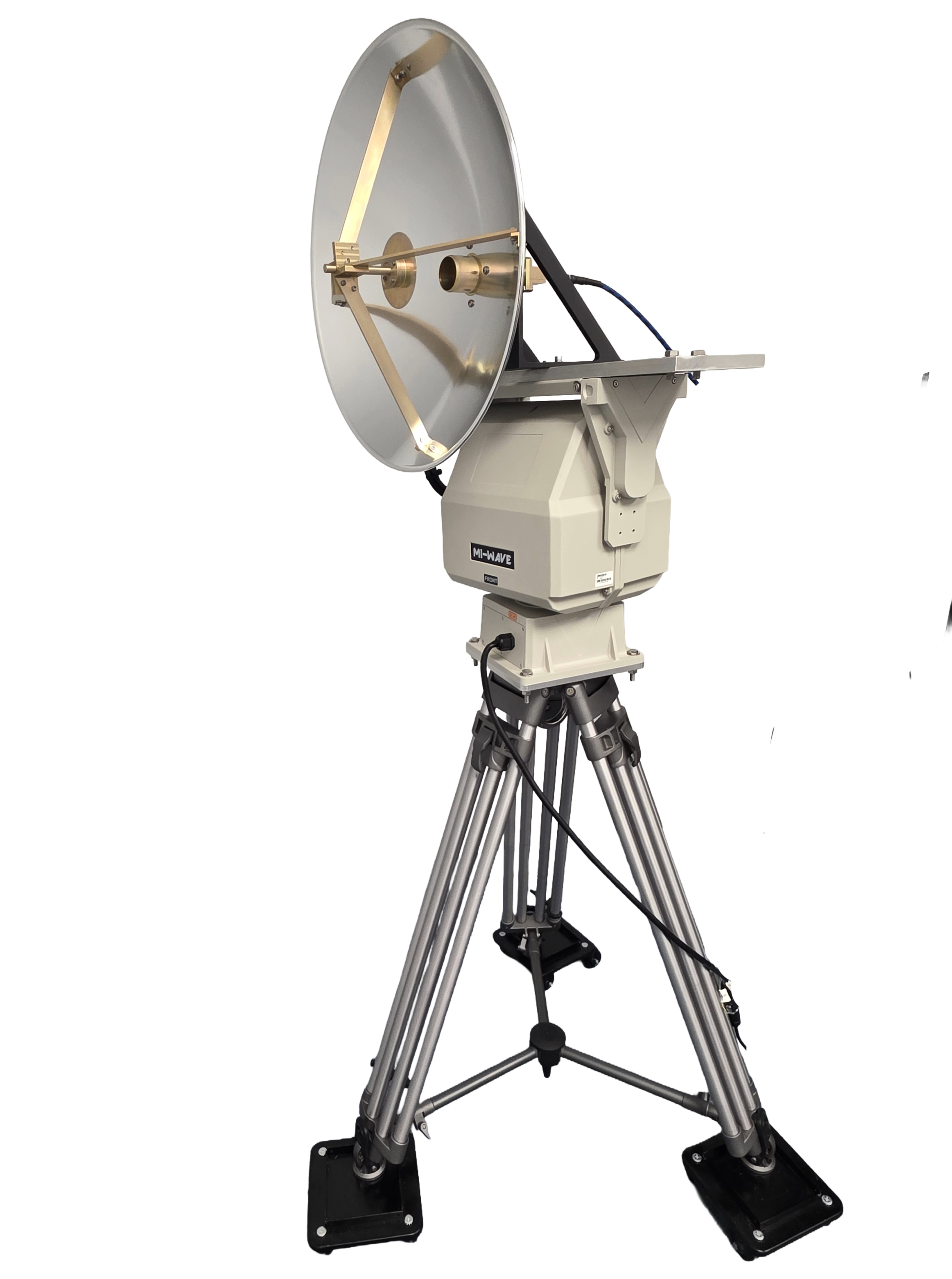
Mi-Wave’s Software-Controlled Antenna Positioner System is a precision motorized positioning platform designed to automate antenna alignment, radiation pattern measurements, gain testing, beamwidth analysis, and general antenna characterization for RF, microwave, and millimeter-wave applications.
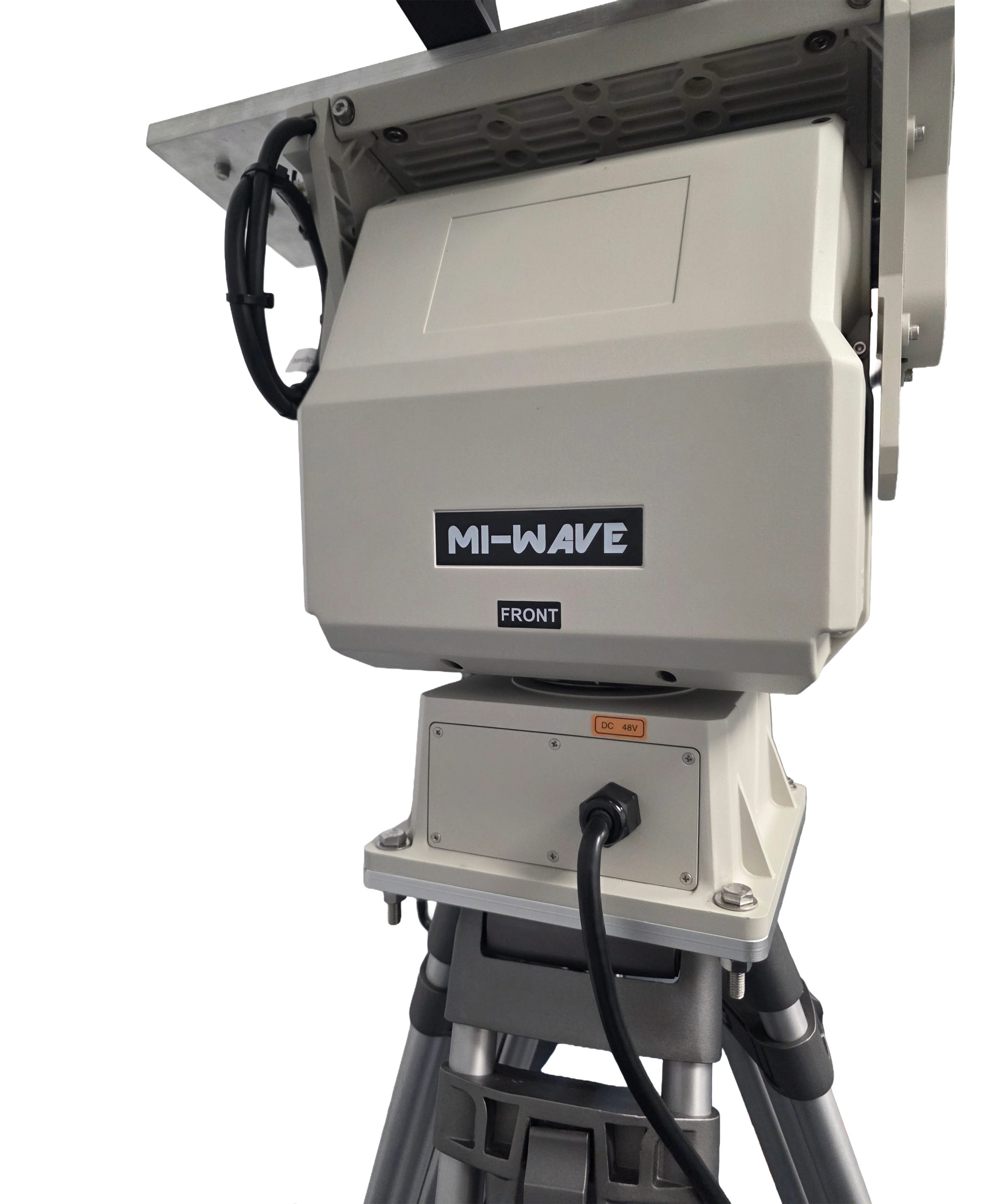
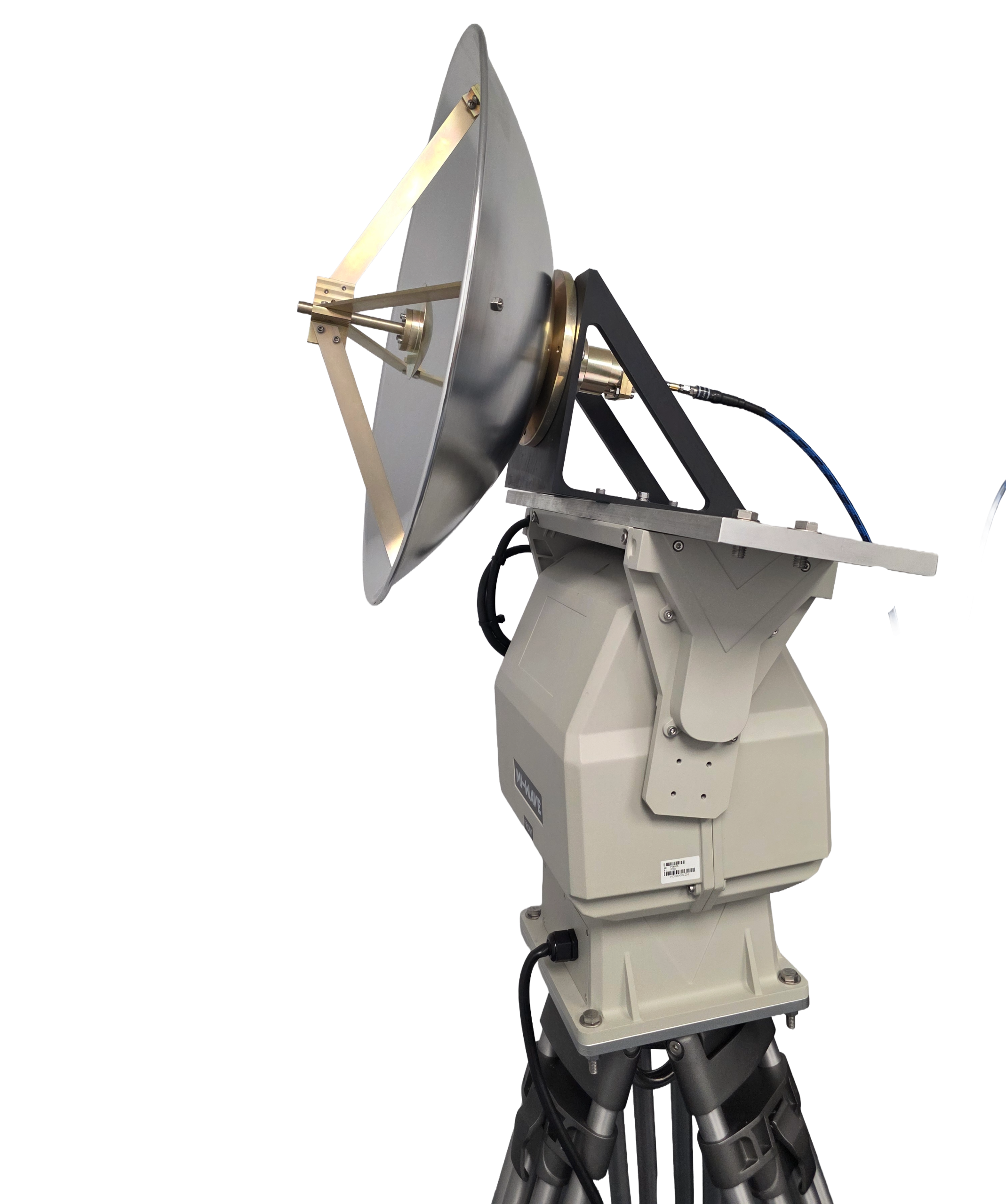
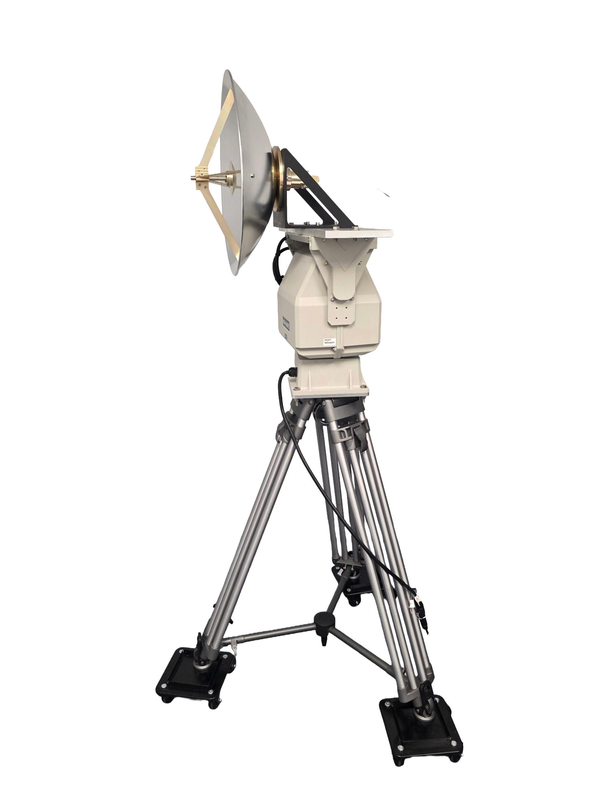
The system combines a rugged motorized antenna positioner, intuitive Windows-based control software, and a heavy-duty tripod into a complete solution for laboratory and field antenna testing. By providing precise computer-controlled movement in both azimuth (pan) and elevation (tilt), the system eliminates manual antenna positioning, improves measurement repeatability, and significantly reduces testing time.
The included software provides complete motion control, automated scan sequencing, programmable home positions, and direct integration with compatible spectrum analyzers for automated data acquisition. Users can perform manual positioning, execute programmable angular scans, capture marker amplitudes, record complete spectrum traces, and export measurement results directly to CSV files for further analysis in Excel or third-party software.
Designed for research laboratories, antenna manufacturers, aerospace and defense organizations, universities, and RF test facilities, the Software-Controlled Antenna Positioner System provides a flexible platform for antenna characterization across a wide range of frequencies and antenna types.
Every antenna installation is different. Mi-Wave offers custom antenna mounting fixtures designed specifically for individual antenna dimensions, weights, and mounting requirements, allowing the positioner to accommodate a broad range of horn antennas, reflector antennas, feed systems, and custom RF assemblies.
The standard models shown represent only part of Mi-Wave’s broader product capabilities. Custom configurations are available to support specific frequency bands, interfaces, and application requirements, enabling optimized solutions for specialized RF, microwave, and millimeter-wave systems.
Watch our informational video to learn more about this product family, including its key features, operating principles, and common applications.
Key Features & Performance Benefits
Computer-Controlled Pan & Tilt Positioning
Provides precise motorized control of both azimuth and elevation directly from the included Windows software.
Automated Antenna Scanning
Automatically performs programmable antenna scans using user-defined start angles, stop angles, step sizes, dwell times, and scan direction.
Manual Motion Control
Directional controls allow quick antenna alignment and positioning during system setup.
Absolute Position Control
Move directly to any desired pan or tilt angle without manual adjustment.
Programmable Home Position
Define and recall a repeatable reference position for consistent testing between multiple measurement sessions.
Angles Relative to Home
Perform scans relative to the antenna boresight rather than mechanical zero, simplifying radiation pattern measurements and beamwidth analysis.
Spectrum Analyzer Integration
Communicates directly with compatible network-connected spectrum analyzers for automated data collection.
Automated Data Capture
Collects antenna amplitude measurements during scans and automatically exports results to CSV format.
Marker Amplitude Capture
Records individual marker measurements from the connected spectrum analyzer.
Full Trace Capture
Captures complete spectrum analyzer traces for frequency response, bandwidth, and RF system analysis.
CSV Export
Measurement data can be imported directly into Microsoft Excel or third-party analysis software.
Adjustable Scan Parameters
Configure:
- Start Angle
- Stop Angle
- Step Size
- Dwell Time
- Scan Direction
- Return to Home
Custom Antenna Fixtures
Custom mounting adapters are available for virtually any antenna geometry or size.
Rugged Tripod Included
Heavy-duty tripod provides stable operation in both laboratory and field environments.
Applications
Antenna Radiation Pattern Measurements
Automates azimuth and elevation scans for far-field and near-field antenna pattern characterization.
Antenna Gain Testing
Provides repeatable positioning for comparative gain measurements and reference antenna calibration.
Beamwidth Analysis
Supports automated half-power beamwidth measurements using programmable scan angles.
Antenna Development
Ideal for prototype evaluation, design verification, and performance optimization.
RF Test & Measurement
Supports RF laboratories performing microwave and millimeter-wave component testing.
Radar Systems
Used for antenna characterization, radar subsystem evaluation, and beam alignment.
Satellite Communications (SatCom)
Supports ground station antenna testing, feed alignment, and satellite antenna evaluation.
EMC & RF Laboratories
Provides controlled antenna positioning for EMC and radiated measurement applications.
University & Research Laboratories
Suitable for educational laboratories and advanced RF research programs.
Aerospace & Defense
Supports antenna testing for airborne, ground-based, and defense communication systems.
Frequently Asked Questions (FAQ)
What is an antenna positioner?
An antenna positioner is a motorized system that precisely rotates an antenna in azimuth (pan) and elevation (tilt) for antenna alignment, radiation pattern measurements, gain testing, beamwidth analysis, and other RF measurement applications.
What is a software-controlled antenna positioner?
A software-controlled antenna positioner allows users to control antenna movement directly from a computer. Position, scan parameters, speed, and automated measurement sequences can all be managed through an intuitive software interface, eliminating manual adjustments and improving repeatability.
What types of antenna measurements can be performed?
The system is ideal for:
- Radiation pattern measurements
- Antenna gain testing
- Beamwidth measurements
- Polarization studies
- Boresight alignment
- Near-field testing
- Far-field testing
- General antenna characterization
Can the positioner control both azimuth and elevation?
Yes. The positioner provides motorized control of both azimuth (pan) and elevation (tilt), allowing complete two-axis antenna positioning.
Can antenna scans be automated?
Yes. Users can configure:
- Start angle
- Stop angle
- Step size
- Dwell time
- Scan direction
- Return to Home
The software automatically moves the antenna through each position while collecting measurement data.
What is the Home Position?
The Home Position is a user-defined reference angle that can be recalled at any time. It provides a repeatable starting point for future scans and simplifies antenna alignment.
What does “Angles Relative to Home” mean?
When enabled, scan angles are referenced to the Home Position instead of the mechanical zero position.
For example, if Home is located at 90°, a scan from –30° to +30° will automatically scan from 60° to 120°, keeping the measurement centered around the antenna boresight.
Can the software communicate with a spectrum analyzer?
Yes. The software can connect to compatible network-enabled spectrum analyzers for automated measurement collection during antenna scans.
What data can be captured?
The software supports:
- Signal amplitude versus angle
- Marker amplitude capture
- Complete spectrum analyzer trace capture
- Automatic CSV data logging
Can measurement data be exported?
Yes. All collected measurement data can be exported to CSV format for analysis in Microsoft Excel or third-party RF analysis software.
Can the positioner perform manual alignment?
Yes. Manual directional controls allow operators to move the antenna during initial setup before beginning automated scans.
Can movement speed be adjusted?
Yes. Users can adjust pan speed to optimize positioning for fine alignment or faster scanning across larger angular ranges.
Are custom antenna mounting fixtures available?
Yes. Mi-Wave offers custom mounting fixtures designed specifically for customer antenna dimensions, weight, and mounting requirements.
What types of antennas can be mounted?
Custom fixtures can be designed for:
- Horn antennas
- Scalar feed horns
- Conical horns
- Lens antennas
- Reflector feeds
- Cassegrain feeds
- OMT assemblies
- Research antennas
- Customer-specific antenna designs
Is the tripod included?
Yes. A heavy-duty tripod is supplied as part of the standard antenna positioner package.
Can the system be used outdoors?
Yes. The heavy-duty tripod and rugged mechanical construction allow operation in both laboratory and outdoor measurement environments.
What industries use antenna positioners?
Typical applications include:
- Aerospace & Defense
- Satellite Communications (SatCom)
- Radar Development
- RF Laboratories
- EMC Testing
- Wireless Communications
- University Research
- Government Laboratories
- Antenna Manufacturing
- Test & Measurement
Can Mi-Wave customize the antenna positioner?
Yes. Custom motion ranges, antenna fixtures, control options, interfaces, and integrated RF measurement solutions are available to meet specific customer requirements.
Antenna Positioner Calculators
Estimate scan time, scan resolution, measurement points, and antenna movement for automated antenna testing and characterization.
Scan Time Calculator
Total Time = (Total Points × Dwell Time) + ((Points − 1) × Move Time)
Scan Points Calculator
Points=((Stop-Start)/Step)+1
Beam Sampling Calculator
Samples = Beamwidth ÷ Step Size
Recommended Step Size
Recommended Step = Beamwidth ÷ 5
Arc Length Calculator
Arc Length = Radius × θ
Degrees ↔ Radians
Glossary of Antenna Positioner Terms
This glossary defines common terminology associated with software-controlled antenna positioners used for RF, microwave, and millimeter-wave antenna testing, radiation pattern measurements, beam characterization, and automated RF measurements.
Positioning Fundamentals
Antenna Positioner
A motorized mechanical system used to accurately rotate an antenna during testing and measurement.
Azimuth (Pan)
Horizontal rotation of the antenna about the vertical axis.
Elevation (Tilt)
Vertical rotation of the antenna above or below the horizon.
Two-Axis Positioner
A positioner capable of controlling both azimuth and elevation simultaneously.
Home Position
A user-defined reference location that can be recalled for repeatable testing.
Relative Angle
Angular movement referenced to the Home Position instead of the mechanical zero position.
Absolute Position
Angular position referenced to the mechanical zero of the positioner.
Boresight
The primary direction in which an antenna radiates maximum energy.
Motion Control
Manual Motion
Direct operator-controlled movement using the software interface.
Position Control
Moving the antenna directly to a specified angular position.
Scan
A programmed sequence of antenna movements over a defined angular range.
Step Size
The angular increment between measurement points during a scan.
Dwell Time
The amount of time the system pauses at each measurement position before collecting data.
Scan Direction
The direction of rotation during a scan, typically clockwise or counterclockwise.
Pan Speed
The rotational speed of the azimuth axis.
Tilt Speed
The rotational speed of the elevation axis.
Motion Controller
The electronic hardware responsible for controlling the positioner’s motors.
Antenna Measurements
Radiation Pattern
A graphical representation of how an antenna radiates RF energy in space.
Beamwidth
The angular width of an antenna’s main radiation lobe, typically measured at the half-power (-3 dB) points.
Half-Power Beamwidth (HPBW)
The angle between the two points where the antenna gain decreases by 3 dB from its maximum value.
Antenna Gain
A measure of how effectively an antenna directs RF energy in a specific direction.
Pattern Cut
A one-dimensional scan of an antenna’s radiation pattern in either azimuth or elevation.
Polar Plot
A circular graph used to display antenna radiation patterns.
Near-Field Measurement
Measurements performed close to the antenna aperture.
Far-Field Measurement
Measurements performed at a sufficient distance where the antenna’s radiation pattern is fully developed.
Data Acquisition
Spectrum Analyzer
An instrument used to measure RF signal amplitude as a function of frequency.
Marker Capture
Recording a single measurement point from the spectrum analyzer.
Trace Capture
Recording the entire spectrum analyzer display for later analysis.
Data Capture
Automatic recording of measurement data during antenna scans.
CSV File
A comma-separated values file used to store measurement data for import into spreadsheet or analysis software.
Measurement Automation
The automatic coordination of antenna movement and RF data collection.
RF System Terms
Radio Frequency (RF)
Electromagnetic signals used for communications, radar, sensing, and testing.
Microwave
Generally refers to frequencies from approximately 1 GHz to 30 GHz.
Millimeter-Wave (mmWave)
Typically refers to frequencies between 30 GHz and 300 GHz.
Frequency
The number of electromagnetic wave cycles occurring each second, typically expressed in GHz.
Wavelength
The physical length of one cycle of an electromagnetic wave.
Applications
Antenna Characterization
Measuring an antenna’s electrical performance, including gain, beamwidth, radiation pattern, and polarization.
Antenna Alignment
Positioning an antenna toward its intended target or boresight direction.
Antenna Test Range
A controlled environment used for antenna measurements and validation.
RF Test & Measurement
The evaluation of RF components and systems using specialized instrumentation.
EMC Testing
Electromagnetic compatibility testing used to evaluate radiated emissions and susceptibility.
Satellite Communications (SatCom)
Communication systems that transmit and receive RF signals through satellites.
Radar Systems
Systems that transmit and receive RF energy for detection, tracking, navigation, and sensing applications.
Research & Development (R&D)
Engineering and scientific development involving experimental RF, microwave, and antenna technologies.
Interested in this product or other Mi-Wave solutions?
Contact our team to discuss your frequency range, interface needs, and application requirements.
Custom configurations are available for specialized RF, microwave, and millimeter-wave systems.
Return to Products Page
