
Product Description
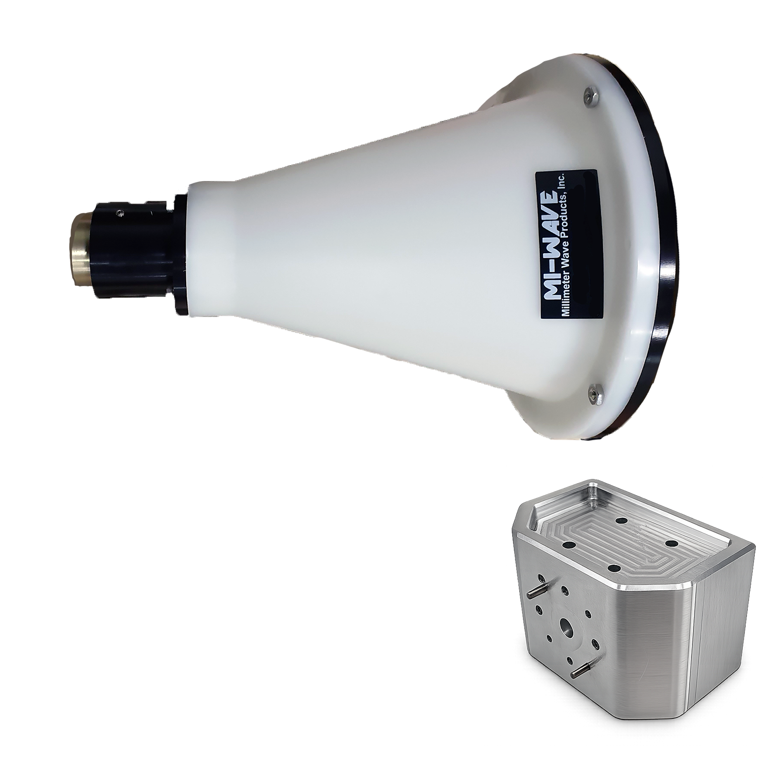
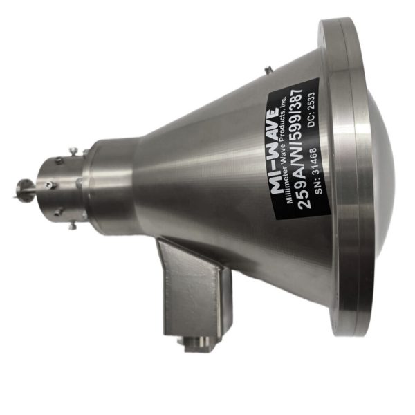
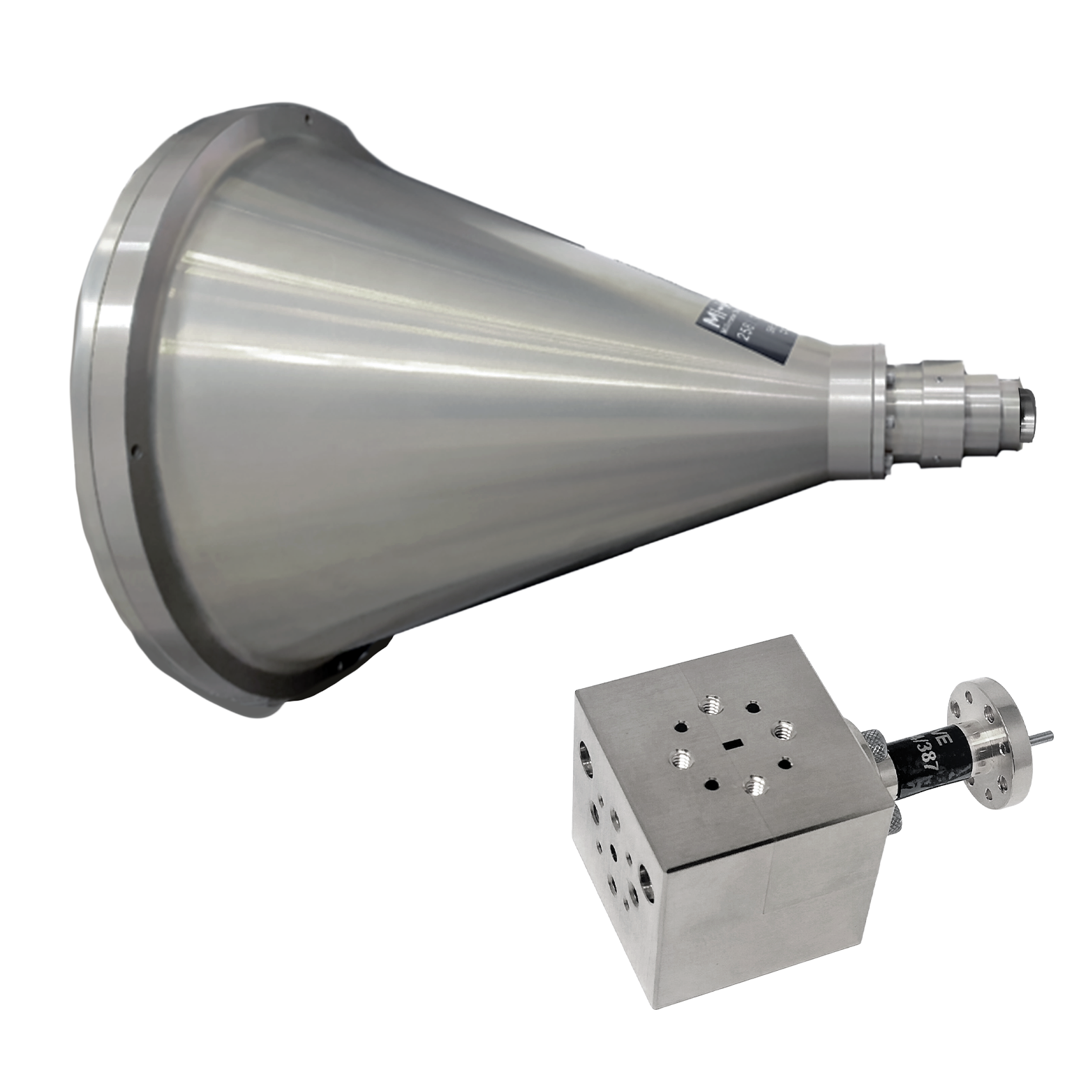
Mi-Wave’s Series 258 Horn Lens Antennas are high-performance directional antennas designed to deliver high gain, low sidelobes, precise beam control, and stable radiation patterns across RF, microwave, and millimeter-wave frequency bands from 8.2 to 170 GHz.
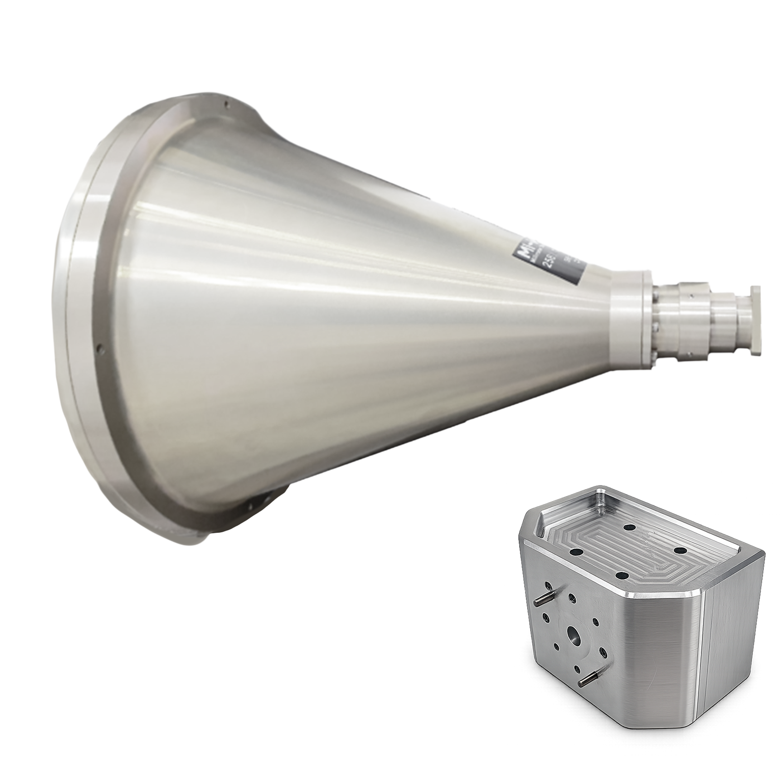
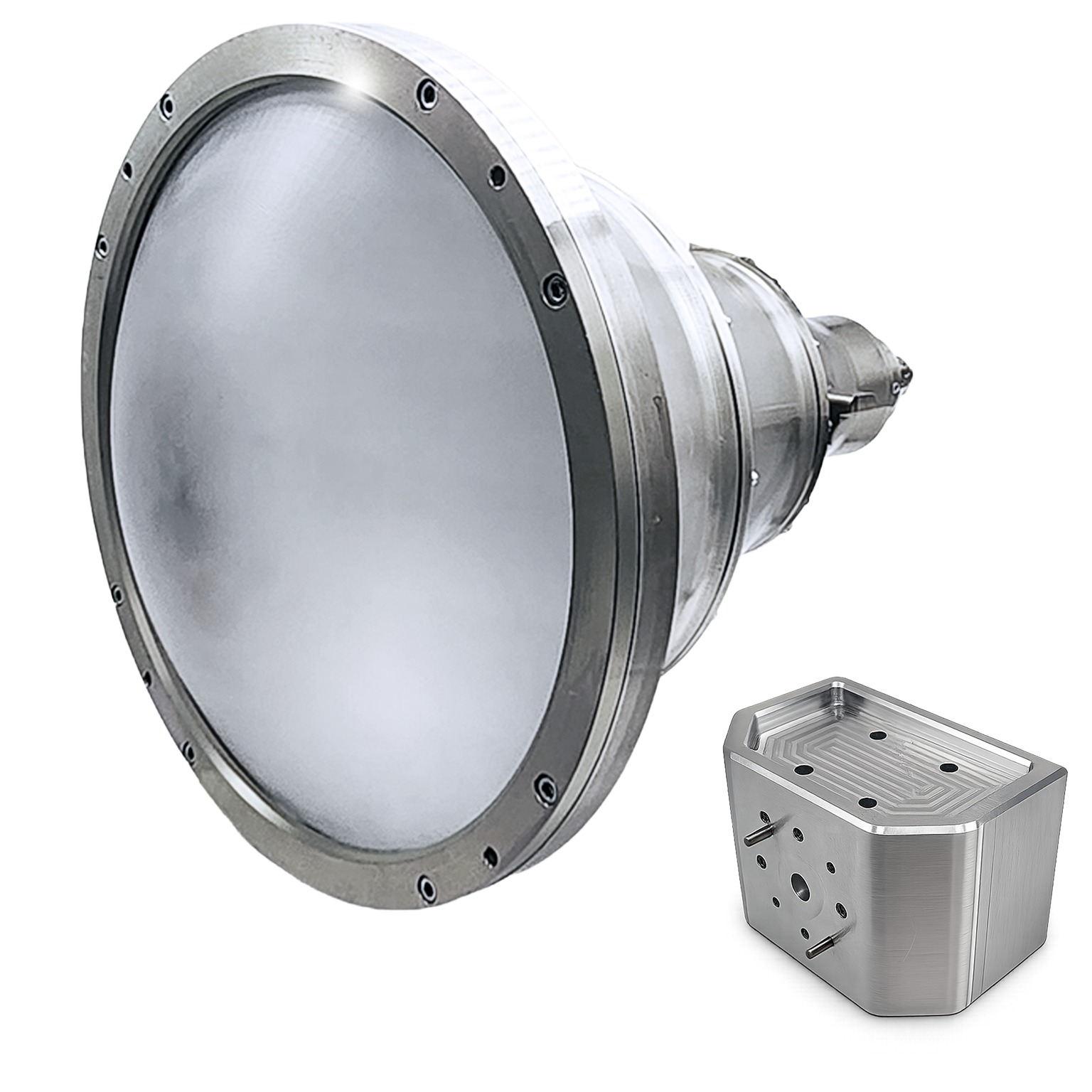
By combining the broadband characteristics of a horn antenna with the focusing capability of a dielectric or metal lens, these antennas improve directivity, aperture efficiency, and beam shaping across wide frequency ranges.
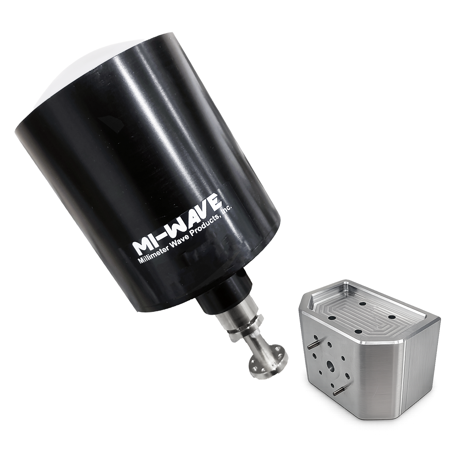
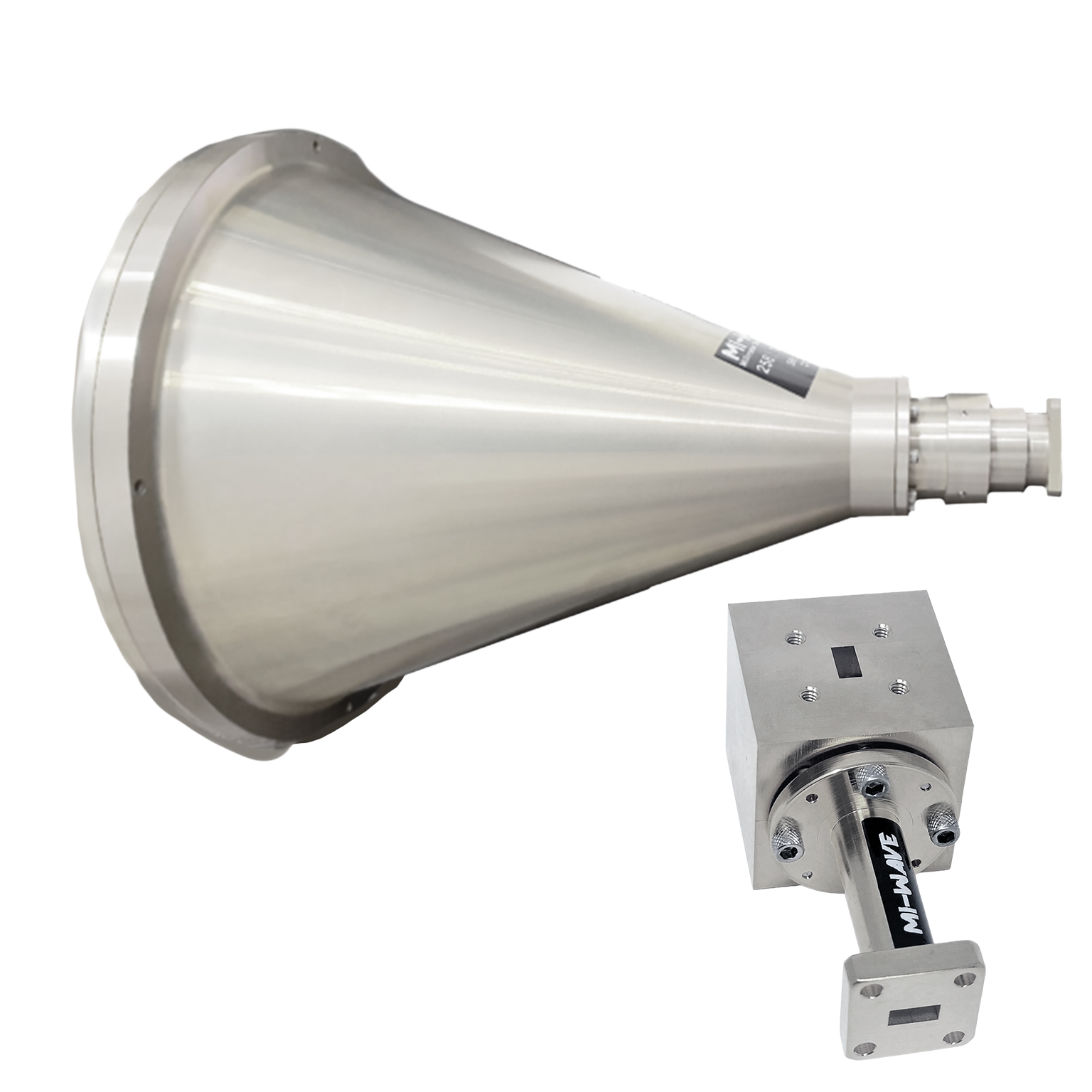
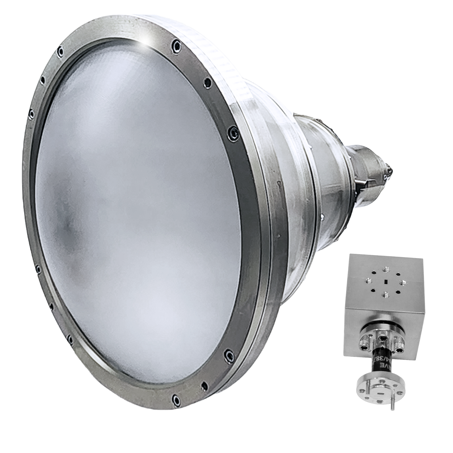
For dual-polarized operation, Series 258 Horn Lens Antennas can be integrated with Mi-Wave’s Series 281 Orthomode Transducer (OMT) to support separate Vertical (V) and Horizontal (H) polarization paths through the same antenna aperture. This allows two orthogonal RF channels to transmit or receive simultaneously while maintaining high isolation between channels.
Series 258 Horn Lens Antennas are well suited for SatCom, radar systems, antenna measurement ranges, RF laboratories, and millimeter-wave research applications where high gain, low distortion, stable polarization performance, and precision beam characteristics are required. Custom configurations are available for specific frequency bands, gain levels, polarization needs, interfaces, and mechanical requirements.
RF Orthomode Transducers
The standard models shown represent only part of Mi-Wave’s broader product capabilities. Custom configurations are available to support specific frequency bands, interfaces, and application requirements, enabling optimized solutions for specialized RF, microwave, and millimeter-wave systems.
| Model No. | Waveguide Band | Reflector diameter (inches) | Circular Waveguide Internal Diameter (.XXX in Model No.) in Inches | Frequency Range (GHz) | Gain (dB) (XX in Model No) | 3 dB Beamwidth (degree) | Polarization | Antenna Port | Housing material | Link |
|---|---|---|---|---|---|---|---|---|---|---|
| 258X-12/.XXX/39-DP | X Band | 12 | .XXX=1.094 .XXX=.938 .XXX= .797 | 8.2-9.97 8.5-11.6 9.97-12.4 | 26 | 6.5 | Vertical | Horizontal | Circular Waveguide with UG-39/U Flange | Aluminum | |
| 258Ku-9/.XXX/419-DP | Ku Band | 9 | XXX=.660 XXX=.550 | 12.4-14.6 14.6-18 | 27 | 5.8 | Vertical | Horizontal | Circular Waveguide with UG-419/U Flange | Aluminum | |
| 258Ku-12/.XXX/419-DP | Ku Band | 12 | XXX=.660 XXX=.550 | 12.4-14.6 14.6-18 | 30 | 4.5 | Vertical | Horizontal | Circular Waveguide with UG-419/U Flange | Aluminum | |
| 258K-9/.XXX/595-DP | K Band | 9 | XXX=.470 XXX .396 XXX=.328 | 18-20.5 20.4-24.5 24.5-26.5 | 30 | 4 | Vertical | Horizontal | Circular Waveguide with UG-595/U Flange or UG-425/U Flange | Aluminum | |
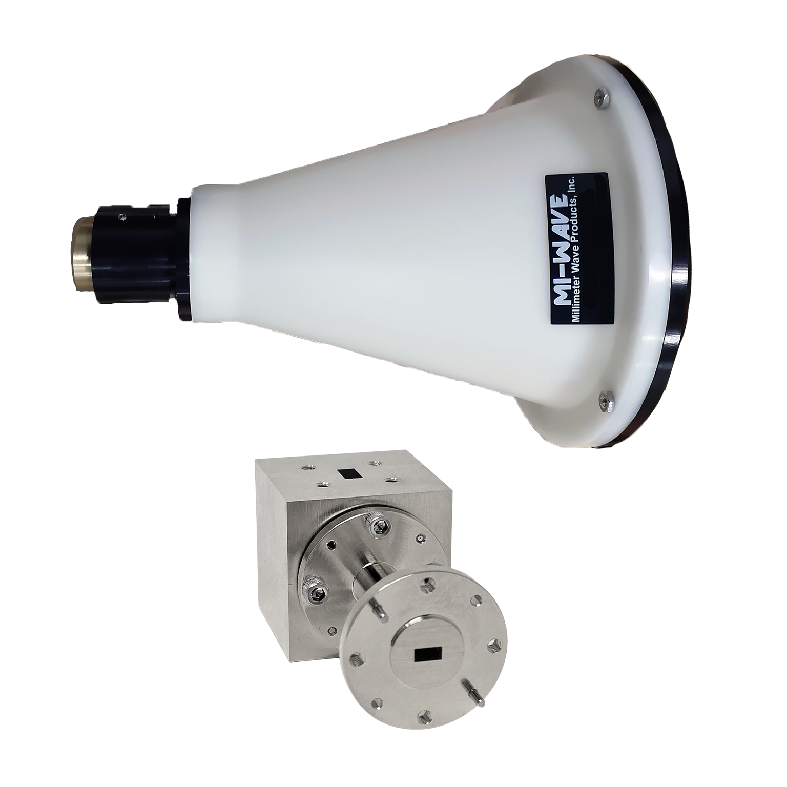
| 258K-6/.XXX/595-DP | K Band | 6 | XXX=.470 XXX .396 XXX=.328 | 18-20.5 20.4-24.5 24.5-26.5 | 26.5 | 6 | Vertical | Horizontal | Circular Waveguide with UG-595/U Flange or UG-425/U Flange | HDPE | |
| 258K-12/.XXX/595-DP | K Band | 12 | XXX=.470 XXX .396 XXX=.328 | 18-20.5 20.4-24.5 24.5-26.5 | 33 | 3 | Vertical | Horizontal | Circular Waveguide with UG-595/U Flange or UG-425/U Flange | Aluminum | |
| 258A-6/.XXX/599-DP | Ka-Band | 6 | XXX=.328 XXX=.281 XXX=.250 XXX= .219 | 26.5-28.5 28.5-33.0 33.0 -38.5 38.5-40.0 | 30 | 4.2 | Vertical | Horizontal | Circular Waveguide with UG-599/U Flange or UG-381/U Flange | HDPE | |
| 258A-9/.XXX/599-DP | Ka-Band | 9 | XXX=.328 XXX=.281 XXX=.250 XXX= .219 | 26.5-28.5 28.5-33.0 33.0 -38.5 38.5-40.0 | 33 | 3 | Vertical | Horizontal | Circular Waveguide with UG-599/U Flange or UG-381/U Flange | Aluminum | |
| 258A-12/.XXX/599-DP | Ka-Band | 12 | XXX=.328 XXX=.281 XXX=.250 XXX= .219 | 26.5-28.5 28.5-33.0 33.0 -38.5 38.5-40.0 | 36 | 2 | Vertical | Horizontal | Circular Waveguide with UG-599/U Flange or UG-381/U Flange | Aluminum | |
| 258B-3/.XXX/383-DP | Q-band | 3 | XXX=.250 XXX=.219 XXX=.188 | 33.0-38.5 38.5-43.0 43.0-50.0 | 26 | 6.5 | Vertical | Horizontal | Circular Waveguide with UG-383/U Flange | Aluminum | |
| 258B-6/.XXX/383-DP | Q-band | 6 | XXX=.250 XXX=.219 XXX=.188 | 33.0-38.5 38.5-43.0 43.0-50.0 | 32 | 3.5 | Vertical | Horizontal | Circular Waveguide with UG-383/U Flange | HDPE | |
| 258B-9/.XXX/383-DP | Q-band | 9 | XXX=.250 XXX=.219 XXX=.188 | 33.0-38.5 38.5-43.0 43.0-50.0 | 36 | 2.5 | Vertical | Horizontal | Circular Waveguide with UG-383/U Flange | Aluminum | |
| 258B-12/.XXX/383-DP | Q-band | 12 | XXX=.250 XXX=.219 XXX=.188 | 33.0-38.5 38.5-43.0 43.0-50.0 | 38.5 | 1.7 | Vertical | Horizontal | Circular Waveguide with UG-383/U Flange | Aluminum | |
| 258U-3/.XXX/383-DP | U-band | 3 | XXX=.219 XXX=.188 XXX=.165 XXX=.141 | 38.5-43.0 43.0-50.0 50.0-58.0 58.0-60.0 | 28 | 5.5 | Vertical | Horizontal | Circular Waveguide with UG-383/U-M Flange | Aluminum | |
| 258U-6/.XXX/383-DP | U-band | 6 | XXX=.219 XXX=.188 XXX=.165 XXX=.141 | 38.5-43.0 43.0-50.0 50.0-58.0 58.0-60.0 | 34 | 2.8 | Vertical | Horizontal | Circular Waveguide with UG-383/U-M Flange | HDPE | |
| 258U-9/.XXX/383-DP | U-band | 9 | XXX=.219 XXX=.188 XXX=.165 XXX=.141 | 38.5-43.0 43.0-50.0 50.0-58.0 58.0-60.0 | 37.5 | 2 | Vertical | Horizontal | Circular Waveguide with UG-383/U-M Flange | Aluminum | |
| 258U-12/.XXX/383-DP | U-band | 12 | XXX=.219 XXX=.188 XXX=.165 XXX=.141 | 38.5-43.0 43.0-50.0 50.0-58.0 58.0-60.0 | 39 | 1.5 | Vertical | Horizontal | Circular Waveguide with UG-383/U-M Flange | Aluminum | |
| 258V-3/.XXX/385-DP | V-band | 3 | XXX=.165 XXX=.141 XXX=.125 | 50.0-58.0 58.0-68.0 68.0-75.0 | 30 | 4.5 | Vertical | Horizontal | Circular Waveguide with UG-385/U Flange | Aluminum | |
| 258V-6/.XXX/385-DP | V-band | 6 | XXX=.165 XXX=.141 XXX=.125 | 50.0-58.0 58.0-68.0 68.0-75.0 | 36 | 2.5 | Vertical | Horizontal | Circular Waveguide with UG-385/U Flange | HDPE | |
| 258V-9/.XXX/385-DP | V-band | 9 | XXX=.165 XXX=.141 XXX=.125 | 50.0-58.0 58.0-68.0 68.0-75.0 | 39 | 1.5 | Vertical | Horizontal | Circular Waveguide with UG-385/U Flange | Aluminum | |
| 258V-12/.XXX/385-DP | V-band | 12 | XXX=.165 XXX=.141 XXX=.125 | 50.0-58.0 58.0-68.0 68.0-75.0 | 42 | 1.2 | Vertical | Horizontal | Circular Waveguide with UG-385/U Flange | Aluminum | |
| 258E-3/.XXX/387-DP | E-band | 3 | XXX=.141 XXX=.125 XXX=.110 XXX=.094 | 60.0-68.0 68.0-77.0 77.0-87.0 87.0-90.0 | 31 | 3.5 | Vertical | Horizontal | Circular Waveguide with UG-387/U Flange | Aluminum | |
| 258E-6/.XXX/387-DP | E-band | 6 | XXX=.141 XXX=.125 XXX=.110 XXX=.094 | 60.0-68.0 68.0-77.0 77.0-87.0 87.0-90.0 | 37 | 1.8 | Vertical | Horizontal | Circular Waveguide with UG-387/U Flange | HDPE | |
| 258E-9/.XXX/387-DP | E-band | 9 | XXX=.141 XXX=.125 XXX=.110 XXX=.094 | 60.0-68.0 68.0-77.0 77.0-87.0 87.0-90.0 | 41 | 1.2 | Vertical | Horizontal | Circular Waveguide with UG-387/U Flange | Aluminum | |
| 258E-12/.XXX/387-DP | E-band | 12 | XXX=.141 XXX=.125 XXX=.110 XXX=.094 | 60.0-68.0 68.0-77.0 77.0-87.0 87.0-90.0 | 43 | 1 | Vertical | Horizontal | Circular Waveguide with UG-387/U Flange | Aluminum | |
| 258W-3/.XXX/387-DP | W-band | 3 | XXX=.125 XXX=.110 XXX=.094 XXX=.082 | 75.0-77.0 77.0-87.0 87.0-100.0 100.0-110.0 | 33 | 2.9 | Vertical | Horizontal | Circular Waveguide with UG-387/U-M Flange | Aluminum | |
| 258W-6/.XXX/387-DP | W-band | 6 | XXX=.125 XXX=.110 XXX=.094 XXX=.082 | 75.0-77.0 77.0-87.0 87.0-100.0 100.0-110.0 | 39 | 1.5 | Vertical | Horizontal | Circular Waveguide with UG-387/U-M Flange | HDPE | |
| 258W-9/.XXX/387-DP | W-band | 9 | XXX=.125 XXX=.110 XXX=.094 XXX=.082 | 75.0-77.0 77.0-87.0 87.0-100.0 100.0-110.0 | 42 | 1 | Vertical | Horizontal | Circular Waveguide with UG-387/U-M Flange | Aluminum | |
| 258W-12/.XXX/387-DP | W-band | 12 | XXX=.125 XXX=.110 XXX=.094 XXX=.082 | 75.0-77.0 77.0-87.0 87.0-100.0 100.0-110.0 | 45 | 0.8 | Vertical | Horizontal | Circular Waveguide with UG-387/U-M Flange | Aluminum | |
| 258F-3/.XXX/387-DP | F-band | 3 | XXX=.094 XXX=.082 XXX=.075 XXX=.067 | 87.0-100.0 100.0-112.0 112.0-125.0 125.0-140.0 | 35.5 | 2.26 | Vertical | Horizontal | Circular Waveguide with UG-387/U-M Flange | Aluminum | |
| 258F-6/.XXX/387-DP | F-band | 6 | XXX=.094 XXX=.082 XXX=.075 XXX=.067 | 87.0-100.0 100.0-112.0 112.0-125.0 125.0-140.0 | 40.5 | 1.13 | Vertical | Horizontal | Circular Waveguide with UG-387/U-M Flange | HDPE | |
| 258F-9/.XXX/387-DP | F-band | 9 | XXX=.094 XXX=.082 XXX=.075 XXX=.067 | 87.0-100.0 100.0-112.0 112.0-125.0 125.0-140.0 | 43.5 | 0.75 | Vertical | Horizontal | Circular Waveguide with UG-387/U-M Flange | Aluminum | |
| 258F-12/.XXX/387-DP | F-band | 12 | XXX=.094 XXX=.082 XXX=.075 XXX=.067 | 87.0-100.0 100.0-112.0 112.0-125.0 125.0-140.0 | 46.5 | 0.57 | Vertical | Horizontal | Circular Waveguide with UG-387/U-M Flange | Aluminum | |
| 258D-3/.XXX/387-DP | D-band | 3 | XXX=.082 XXX=.075 XXX=.067 XXX=.059 | 100.0-112.0 112.0-125.0 125.0-140.0 140.0-160.0 | 36 | 1.86 | Vertical | Horizontal | Circular Waveguide with UG-387/U-M Flange | Aluminum | |
| 258D-12/.XXX/387-DP | D-band | 12 | XXX=.082 XXX=.075 XXX=.067 XXX=.059 | 100.0-112.0 112.0-125.0 125.0-140.0 140.0-160.0 | 48 | 0.46 | Vertical | Horizontal | Circular Waveguide with UG-387/U-M Flange | Aluminum | |
| 258D-6/.XXX/387-DP | D-band | 6 | XXX=.082 XXX=.075 XXX=.067 XXX=.059 | 100.0-112.0 112.0-125.0 125.0-140.0 140.0-160.0 | 42 | 0.93 | Vertical | Horizontal | Circular Waveguide with UG-387/U-M Flange | HDPE | |
| 258D-9/.XXX/387-DP | D-band | 9 | XXX=.082 XXX=.075 XXX=.067 XXX=.059 | 100.0-112.0 112.0-125.0 125.0-140.0 140.0-160.0 | 45.5 | 0.62 | Vertical | Horizontal | Circular Waveguide with UG-387/U-M Flange | Aluminum |
*All data presented is collected from a sample lot.
* Actual data may vary unit to unit, slightly.
*All testing was performed under +25 °C case temperature.
*Consult factory to confirm if material, plating, size, shape, orientation and any electrical parameter is critical for the application as website information is for reference only.
*Millimeter Wave Products, Inc. reserves the right to change the information presented on website without notice as we continue to enhance the performance and design of our products.
Key Features & Performance Benefits
High Gain & Enhanced Directivity
Horn lens antennas combine horn radiation with lens-based wavefront shaping to produce strong directional gain and efficient RF energy focusing across microwave and millimeter-wave frequencies.
Dual-Polarization Capability
Series 258 Horn Lens Antennas can be integrated with Mi-Wave’s Series 281 Orthomode Transducer (OMT) to support separate Vertical (V) and Horizontal (H) polarization paths through the same antenna aperture. This enables simultaneous dual-channel operation while maintaining high isolation between polarization channels.
Low Sidelobe Performance
The lens helps control aperture illumination and radiation distribution, reducing unwanted sidelobes and improving beam cleanliness. This is especially valuable in radar, antenna measurement, and interference-sensitive systems.
Wideband Frequency Coverage
Series 258 Horn Lens Antennas support broad frequency operation from 8.2 to 170 GHz, making them suitable for RF, microwave, and millimeter-wave applications.
Precise Beam Shaping
The lens provides additional control over the radiated wavefront, helping optimize beamwidth, improve pattern uniformity, and reduce distortion compared to standard horn antennas.
Improved Aperture Efficiency
By focusing more RF energy into the desired radiation pattern, the horn lens design improves aperture utilization and overall antenna efficiency.
Stable Radiation Patterns
Horn lens antennas provide consistent and repeatable performance across frequency bands, making them ideal for calibration, measurement, and high-precision RF systems.
Low Phase Distortion
The lens helps maintain a more uniform phase front across the antenna aperture, reducing phase errors and improving signal quality in high-frequency systems.
Optimized for High-Frequency Applications
These antennas are well suited for microwave and millimeter-wave systems where tight beam control, low loss, stable polarization performance, and signal integrity are critical.
Compact High-Performance Design
Compared to larger reflector antenna systems, horn lens antennas provide a more compact solution while still delivering high gain, controlled beamwidth, and stable radiation performance.
Flexible Configuration Options
Available in multiple sizes, frequency bands, lens types, gain levels, and polarization configurations, Series 258 Horn Lens Antennas can be tailored for specific RF system requirements.
How Horn Lens Antennas Work
Mi-Wave’s Series 258 Horn Lens Antennas combine the broadband characteristics of horn antennas with the focusing capability of dielectric or metal lens structures to produce high gain, stable beam patterns, and precise RF energy control across microwave and millimeter-wave frequency bands.
These antennas are designed to improve aperture efficiency, reduce sidelobes, and maintain smooth radiation behavior in high-frequency RF systems where beam quality and directional control are critical.
For dual-polarized operation, Series 258 Horn Lens Antennas can integrate with Mi-Wave’s Series 281 Orthomode Transducer (OMT) to support separate Vertical (V) and Horizontal (H) polarization paths through the same antenna aperture.
Orthogonal Polarizations
RF Signals Enter the Feed
Vertical and Horizontal RF channels enter through separate polarization paths or waveguide interfaces.
Polarization Separation
The Series 281 OMT separates or combines orthogonal polarization channels while maintaining high isolation.
Horn Antenna Expansion
RF energy expands through the horn structure, increasing aperture size and improving directivity.
Lens Focusing
The dielectric or metal lens helps focus and shape the RF energy to improve beam symmetry and gain.
Controlled Radiation Patterns
The combined horn and lens structure produces stable radiation patterns with low sidelobes and predictable beam behavior.
Dual-Polarized Operation
Both Vertical and Horizontal polarization channels can operate simultaneously through the same antenna aperture.
pplications
Mi-Wave Series 258 Horn Lens Antennas are used in RF, microwave, and millimeter-wave systems that require high gain, low sidelobes, precise beam control, and stable radiation patterns. Their horn-lens design helps improve directivity, reduce distortion, and support repeatable performance in both communication systems and high-precision RF environments.
For dual-polarized systems, Series 258 Horn Lens Antennas can be integrated with Mi-Wave’s Series 281 Orthomode Transducer (OMT) to support separate Vertical (V) and Horizontal (H) polarization paths through the same antenna aperture.
Satellite Communications
Used in ground terminals, gateway systems, uplink/downlink testing, Ka-band, Q-band, V-band, and W-band communication links where controlled beam shaping and low sidelobe performance help improve link quality and reduce interference.
Radar Systems & Testing
Ideal for radar cross-section testing, target illumination, FMCW and pulse radar platforms, radar calibration, and microwave or millimeter-wave radar research where focused beam performance and high directivity are critical.
Antenna Measurement Ranges
Used for antenna gain measurements, radiation pattern testing, near-field and far-field testing, beamwidth verification, sidelobe evaluation, and calibration of RF measurement systems.
RF & Microwave Laboratory Research
Supports millimeter-wave prototyping, wireless propagation studies, RF component testing, subsystem validation, antenna development, and academic, government, or commercial research programs.
EMC & RF Testing
Useful for radiated emissions testing, RF susceptibility testing, controlled illumination of devices under test, shielding effectiveness testing, and EMC compliance validation where directional RF control improves repeatability.
Frequently Asked Questions (FAQ)
What is a horn lens antenna?
A horn lens antenna is a directional antenna that combines a horn radiator with a dielectric or metal lens to improve beam focusing, increase gain, and reduce sidelobes. This design provides improved beam control compared to standard horn antennas.
What are the advantages of horn lens antennas?
Horn lens antennas provide high gain, low sidelobes, stable radiation patterns, improved directivity, and precise beam control. They are especially useful in high-frequency microwave and millimeter-wave systems.
What frequencies do Series 258 Horn Lens Antennas support?
Mi-Wave Series 258 Horn Lens Antennas support operation from approximately 8.2 GHz to 170 GHz, depending on the specific antenna configuration.
How does the lens improve antenna performance?
The lens shapes and focuses the electromagnetic wavefront as it exits the horn aperture. This improves aperture efficiency, beam symmetry, sidelobe suppression, and overall radiation performance.
Can horn lens antennas support dual polarization?
Yes. Series 258 Horn Lens Antennas can integrate with Mi-Wave’s Series 281 Orthomode Transducer (OMT) to support separate Vertical (V) and Horizontal (H) polarization paths through the same antenna aperture.
What determines gain in a horn lens antenna?
Antenna gain is primarily determined by aperture size, operating frequency, and overall antenna efficiency. Larger apertures and higher frequencies generally produce higher gain.
What is beamwidth in a horn lens antenna?
Beamwidth is the angular width of the antenna’s main radiation beam. Horn lens antennas produce narrow, well-controlled beamwidths for improved signal focus and measurement accuracy.
What are horn lens antennas commonly used for?
Series 258 Horn Lens Antennas are commonly used in:
- Satellite communications (SatCom)
- Radar systems
- Antenna measurement ranges
- RF and microwave laboratories
- EMC and RF testing
- Millimeter-wave research
Are horn lens antennas suitable for RF measurement applications?
Yes. Their low sidelobe levels, stable beam patterns, and predictable performance make them ideal for antenna calibration, gain measurements, and precision RF testing.
Can horn lens antennas be customized?
Yes. Mi-Wave offers custom horn lens antenna configurations for specific frequency ranges, gain targets, polarization requirements, lens types, and mechanical interfaces.
What materials are used in horn lens antennas?
Horn lens antennas typically use precision-machined metal horn structures combined with dielectric or metal lens elements depending on frequency, performance requirements, and environmental considerations.
Why use a dielectric lens in a horn antenna?
Dielectric lenses help improve beam shaping and directivity while reducing overall antenna weight. They are commonly used in laboratory systems, field deployments, and integrated RF platforms.
Horn Lens Antenna Engineering Calculators
Spot Focus Antenna Engineering Calculators
These RF engineering calculators help estimate antenna performance for spot focus antennas, including communications systems, radar platforms, antenna measurement ranges, and microwave and millimeter-wave test environments. Use them to calculate antenna gain, beamwidth, reflector diameter required for target gain, effective aperture, free-space path loss, and wavelength across RF, microwave, and millimeter-wave frequencies.
Spot focus antennas are designed for tight beamwidth, focused energy distribution, and strong directional performance. A typical starting efficiency range for many systems is 0.50 to 0.70.
Antenna Gain Calculator
Antenna Gain (dBi):
Antenna Beamwidth Calculator
Reflector Size Required for Target Gain
Antenna Effective Aperture Calculator
Effective Aperture (m²):
Free Space Path Loss Calculator
RF Wavelength Calculator
Wavelength (mm):
Glossary of Horn Lens Antenna Terms
This glossary defines common terminology related to horn lens antennas used in RF, microwave, and millimeter-wave systems requiring high gain, low sidelobes, controlled beam shaping, and stable radiation performance. These antennas are commonly used in satellite communications, radar systems, antenna measurement ranges, RF laboratories, EMC testing, and advanced research platforms.
Antenna Fundamentals
Horn Lens Antenna
A hybrid directional antenna that combines a horn radiator with a dielectric or metal lens to improve gain, directivity, beam shaping, and sidelobe performance.
Horn Antenna
A flared waveguide structure designed to radiate RF energy with broadband performance and controlled directivity.
RF Lens
A dielectric or metallic structure used to focus, shape, or redirect electromagnetic waves to improve antenna radiation characteristics.
Dielectric Lens
A lens made from non-conductive material that refracts RF energy to improve beam focusing and aperture efficiency.
Metal Lens
A conductive lens structure used to shape RF wavefronts in specialized or high-power microwave systems.
Aperture
The radiating opening of an antenna through which RF energy is transmitted or received.
Aperture Area
The physical size of the antenna opening, which directly affects gain, directivity, and beamwidth.
Dual Polarization
A system architecture that supports simultaneous Vertical (V) and Horizontal (H) polarization operation through the same antenna aperture.
Orthomode Transducer (OMT)
A waveguide component used to separate or combine orthogonal polarization paths while maintaining high isolation between channels.
Vertical Polarization (V)
An RF polarization orientation where the electric field is vertically aligned.
Horizontal Polarization (H)
An RF polarization orientation where the electric field is horizontally aligned.
Radiation Characteristics
Antenna Gain
A measure of how effectively an antenna directs RF energy in a specific direction.
Directivity
The ability of an antenna to concentrate RF energy into a preferred radiation direction.
Beamwidth
The angular width of the antenna’s primary radiation beam.
Half-Power Beamwidth (HPBW)
The angle between points where the radiated power decreases by 3 dB from the peak signal level.
Sidelobes
Secondary radiation peaks outside the main beam that can introduce interference or measurement inaccuracies.
Radiation Pattern
A graphical representation of how RF energy is distributed around an antenna.
Beam Shaping
The process of controlling RF wavefront distribution to optimize beamwidth, directivity, or sidelobe performance.
Phase Front
The shape and alignment of the electromagnetic wave as it propagates through space.
Phase Center
The effective point from which RF radiation appears to originate within the antenna structure.
Performance & Efficiency
Aperture Efficiency
The effectiveness of an antenna in converting physical aperture size into usable directional gain.
Effective Aperture (Ae)
The equivalent area over which an antenna effectively captures or radiates RF energy.
Lens Efficiency
The effectiveness of the lens in shaping and focusing RF energy with minimal loss.
Phase Error
Deviation from a uniform phase distribution across the antenna aperture that can degrade beam quality.
Insertion Loss
Signal power lost as RF energy passes through antenna components, transitions, or lens materials.
Spillover Loss
RF energy radiated outside the intended aperture or beam path, reducing antenna efficiency.
VSWR (Voltage Standing Wave Ratio)
A measurement of impedance matching quality between RF components and the antenna system.
Low Sidelobe Performance
A radiation characteristic where unwanted sidelobes are minimized to improve beam cleanliness and reduce interference.
RF & Frequency Terms
Radio Frequency (RF)
Electromagnetic frequencies used for communication, radar, sensing, and wireless systems.
Microwave Frequencies
Typically refers to frequencies between 1 GHz and 30 GHz.
Millimeter-Wave (mmWave)
Generally refers to frequencies from 30 GHz to 300 GHz.
Frequency (f)
The number of electromagnetic wave cycles per second, typically measured in GHz.
Wavelength (λ)
The physical distance between repeating peaks of an electromagnetic wave.
Waveguide
A conductive transmission structure used to guide high-frequency RF energy with low loss.
Broadband Operation
Antenna performance maintained across a wide frequency range.
Applications & Systems
Satellite Communications (SatCom)
Communication systems that use satellites to transmit and receive RF signals across long distances.
Radar Systems
Systems that transmit and receive RF energy to detect, track, or measure objects.
Antenna Measurement Range
A controlled RF environment used for antenna gain, beam pattern, and radiation testing.
EMC Testing
Electromagnetic compatibility testing used to evaluate interference and RF emissions behavior.
RF Test Systems
Equipment and instrumentation used to analyze RF performance in laboratory or production environments.
Millimeter-Wave Research
Research involving high-frequency microwave and mmWave systems for communications, sensing, and advanced RF development.
Common Frequency Bands
L-Band
1–2 GHz
S-Band
2–4 GHz
C-Band
4–8 GHz
X-Band
8–12 GHz
Ku-Band
12–18 GHz
Ka-Band
26–40 GHz
Q-Band
33–50 GHz
V-Band
50–75 GHz
W-Band
75–110 GHz
These frequency bands are commonly used in satellite communications, radar systems, wireless links, test equipment, and millimeter-wave research applications.
Outlines & Drawings
Find your band and view outlines, drawings, data & more.
Interested in this product or other Mi-Wave solutions?
Contact our team to discuss your frequency range, interface needs, and application requirements.
Custom configurations are available for specialized RF, microwave, and millimeter-wave systems.
Return to Dual Polarized Antennas
Return to Antennas
Return to Products Page