

Product Description
Mi-Wave’s 955 Series microwave and millimeter-wave Ka-band RF power amplifiers are engineered for applications requiring high output power, high gain, and stable performance at specific center frequencies. These amplifiers are well suited for laboratory, production, and fielded environments where repeatable RF power and controlled operating conditions are essential.
A representative model in the series is the 955A-29.3/40/41.5/KF/599HAC RF Power Amplifier, designed to operate at a center frequency of 29.3 GHz with a ±0.3 GHz bandwidth, placing it squarely in the Ka-band. This amplifier delivers 40 dB typical small-signal gain, maintaining 40 dB nominal gain across the operating band, and provides +41.5 dBm typical saturated output power (Psat), with +41.1 dBm typical across the band. These characteristics make it well suited for high-power Ka-band transmission, system characterization, and validation tasks.
The amplifier requires a +5 dBm nominal RF input drive, with +8 dBm typical input at Psat, and supports a maximum CW RF input power of +10 dBm. An integrated AC power supply (100–120 VAC) and internal cooling fans simplify bench-top and system integration. Operational safeguards, including proper power sequencing and thermal limits, help ensure long-term reliability when operated within specified conditions.
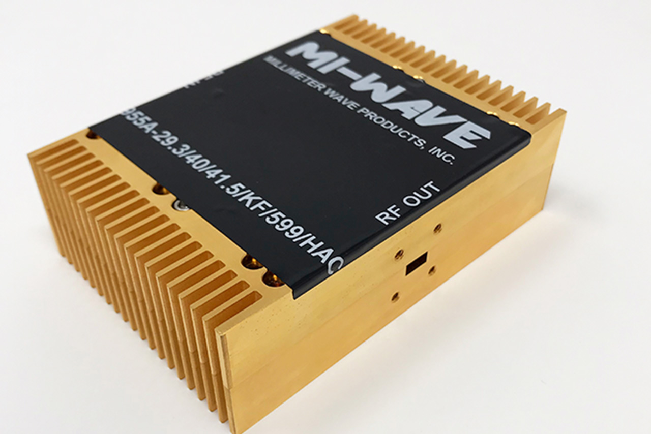
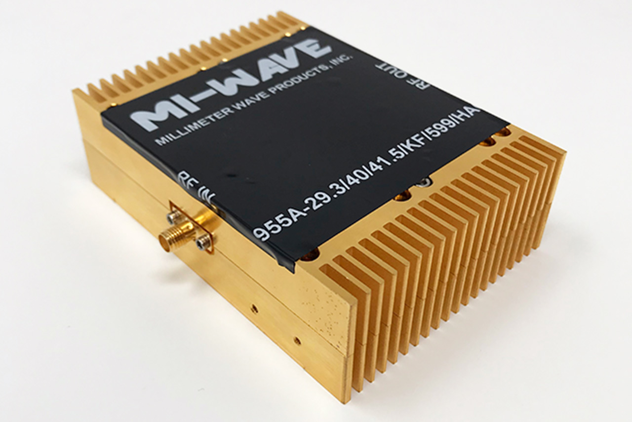
*Actual product may be different from the image shown per customers specifcations
*All data presented is collected from a sample lot.
* Actual data may vary unit to unit, slightly.
*All testing was performed under +25 °C case temperature.
*Consult factory to confirm if material, plating, size, shape, orientation and any electrical parameter is critical for the application as website information is for reference only.
*Millimeter Wave Products, Inc. reserves the right to change the information presented on website without notice as we continue to enhance the performance and design of our products.
Specifications
| Parameter | Specification |
|---|---|
| Model | 955A-29.3/40/41.5/KF/599HAC |
| Center Frequency | 29.3 GHz ± 0.3 GHz |
| Band | Ka-band |
| Small Signal Gain | 40 dB typical |
| 40 dB nominal across operating band | |
| Output Power @ Psat | +41.5 dBm typical |
| +41.1 dBm typical across band | |
| RF Input Drive (Nominal) | +5 dBm |
| RF Input Drive @ Psat | +8 dBm typical |
| Maximum RF Input Power (CW) | +10 dBm |
| AC Power Input | 100 to 120 VAC |
| Cooling | Internal fans enabled via AC power switch |
| Data Reference Temperature | Approximately +23 °C |
| Maximum Recommended Operating Temperature | +45 °C |
| Operational Notes | Proper power-on/off sequencing required |
| Exceeding RF input power or voltage voids warranty | |
| Series | 955 Series |
| Configuration | RF / Microwave Power Amplifier |
Key Features & Performance Benefits
Wide Frequency Coverage
Supports microwave and millimeter-wave frequency bands with configurations tailored to specific application requirements.
High Output Power Options
Designed to deliver stable output power suitable for transmit chains, signal injection, and system-level testing.
Excellent Linearity
Optimized for low distortion, supporting wideband modulation schemes and multi-carrier operation.
Stable Gain and Gain Flatness
Maintains consistent amplification across the operating band, improving system predictability and calibration.
Clean Spectral Performance
Low spurious output and harmonic control help preserve spectral integrity and meet regulatory requirements.
Flexible Integration
Compatible with RF upconverters, frequency synthesizers, and signal generators for modular system architectures.
Thermally Robust Designs
Engineered for reliable operation under continuous-wave and high-duty-cycle conditions.
Multiple Packaging Options
Available in configurations suitable for laboratory use, rack-mount systems, and embedded RF platforms.
Typical Applications for Microwave & Millimeter-Wave Power Amplifiers
Mi-Wave 955 Series microwave and millimeter-wave power amplifiers are used in a wide range of RF transmit, signal conditioning, and system-integration applications where stable output power, linear amplification, and spectral integrity are required.
Satellite Communication (SatCom)
Power amplifiers are critical in satellite uplink chains to boost RF signals prior to transmission.
Common SatCom applications include:
-
Satellite uplink transmit chains
-
VSAT and gateway terminals
-
Ground station and teleport infrastructure
-
Integration with RF upconverters and BUC architectures
-
High-throughput satellite (HTS) systems
Stable gain and controlled output power support clean uplink spectra and regulatory compliance.
Radar and Sensing Systems
In radar platforms, microwave and mmWave power amplifiers provide the necessary transmit power for signal generation and injection.
Typical radar applications include:
-
Surveillance and tracking radar transmitters
-
FMCW and pulse-Doppler radar systems
-
Ground-based, airborne, and maritime radar platforms
-
Radar signal injection and calibration
High linearity and gain stability improve range performance and target detection accuracy.
Point-to-Point Microwave and Millimeter-Wave Links
Power amplifiers support long-distance and high-capacity wireless links.
Applications include:
-
Microwave and mmWave backhaul links
-
Fixed wireless access (FWA) systems
-
Private and critical infrastructure networks
-
High-throughput point-to-point radio systems
Clean amplification helps maintain link margin and spectral efficiency.
5G and Millimeter-Wave Wireless Development
Microwave and mmWave power amplifiers are widely used in development and validation of next-generation wireless systems.
Applications include:
-
5G FR2 base station and small cell testing
-
mmWave transmitter development
-
Beamforming and MIMO system validation
-
Wireless backhaul and access research
Linear amplification is essential for wideband modulation and EVM performance.
RF Test, Measurement, and Research
In laboratory and production environments, power amplifiers provide controlled RF output levels.
Typical uses include:
-
RF and mmWave test benches
-
Signal source amplification
-
Device and subsystem characterization
-
Automated test equipment (ATE)
Repeatable performance supports accurate testing and validation workflows.
Power Amplifier (PA) Calculators
These calculators support PA output level planning, compression headroom (P1dB margin), linearity planning (IIP3/OIP3 and IM3 estimates), EIRP estimates, and quick thermal dissipation approximations for RF, microwave, and millimeter-wave transmit chains.
Jump to: Output Level · P1dB Margin · IIP3 ↔ OIP3 · IM3 Estimate · EIRP · Thermal · dBm ↔ W
1) Output Level Estimator (Pin + Gain − Loss)
Estimate PA output level from input power, small-signal gain, and total losses (attenuators, cables, filters).
2) P1dB Margin (Compression Headroom)
Compute headroom between your estimated output power and the PA 1 dB compression point (P1dB).
3) IIP3 ↔ OIP3 Converter (With Gain)
Convert between input IP3 (IIP3) and output IP3 (OIP3) using gain. Enter any two fields and compute the third.
4) Two-Tone IM3 Estimate (Using OIP3)
Estimate third-order intermodulation (IM3) for a two-tone test. Planning approximation: IM3(dBc) ≈ 2·(OIP3 − Pout_per_tone).
5) EIRP Calculator (Pout + Antenna Gain − Loss)
Compute EIRP from PA output power, antenna gain, and total RF losses (feed, waveguide, radome).
6) Thermal Dissipation Estimate (Pout and Efficiency)
Estimate DC power and heat dissipation from RF output and efficiency. If you have PAE or drain efficiency, enter it as a percent.
7) dBm ↔ Watts Converter
Convert between dBm and Watts for RF power levels. Enter either field and compute the other.
Microwave & Millimeter-Wave Power Amplifier FAQ
These quick answers cover microwave and millimeter-wave RF power amplifiers used in satellite communications (SatCom), radar, point-to-point radio, 5G/mmWave systems, telemetry, electronic warfare, and RF test and measurement applications.
Quick Answers
What does an RF power amplifier do?
An RF power amplifier increases the power level of an RF, microwave, or millimeter-wave signal so it can be efficiently transmitted by an antenna or injected into a system under test. It is typically the final active stage in a transmit signal chain.
How is a power amplifier different from a BUC?
A power amplifier provides RF gain only. A Block Upconverter (BUC) integrates an RF upconverter and a power amplifier into a single unit, combining frequency translation and amplification for satellite uplink applications.
Why is linearity important in microwave power amplifiers?
High linearity minimizes distortion, intermodulation products, and spectral regrowth. This is critical for wideband modulation, multi-carrier signals, low EVM, and regulatory compliance in modern RF systems.
Can power amplifiers be used with RF synthesizers?
Yes. Power amplifiers are commonly paired with RF synthesizers, signal generators, and frequency upconverters to increase output power while maintaining frequency accuracy and spectral purity.
What frequency bands do Mi-Wave power amplifiers cover?
Mi-Wave power amplifiers support a wide range of microwave and millimeter-wave bands, including X-band, Ku-band, Ka-band, Q-band, V-band, and higher frequencies depending on configuration.
More Technical Questions
What determines the required output power of an RF power amplifier?
What is gain flatness and why does it matter?
What is the difference between a driver amplifier and a power amplifier?
Are these power amplifiers suitable for continuous-wave (CW) operation?
How does linearity affect EVM and spectral performance?
Can Mi-Wave provide custom power amplifier designs?
Glossary of RF & Microwave Power Amplifier Terms
Core Power Amplifier Definitions
RF Power Amplifier (PA)
An active RF device that increases the power level of an input signal to drive an antenna, load, or next system stage. RF power amplifiers are used in microwave and millimeter-wave transmit chains for satellite communications, radar, telemetry, wireless infrastructure, and test systems.
Microwave Power Amplifier
A power amplifier designed to operate in microwave frequency bands such as X-, Ku-, Ka-, Q-, V-, and W-band. These amplifiers are optimized for high gain, stability, and controlled output power at high frequencies.
Millimeter-Wave Power Amplifier
A power amplifier operating above 30 GHz, typically used in Ka-band and higher frequency systems. Millimeter-wave amplifiers support applications such as SatCom, radar, 5G/mmWave, and scientific research.
Power, Gain, and Linearity
Small-Signal Gain
The amplification provided by a power amplifier when operating below compression. Specified in dB, small-signal gain defines how much the input signal is increased under linear conditions.
Output Power
The RF power delivered by the amplifier at its output port, typically specified in dBm or watts. Output power requirements are driven by link budgets, antenna gain, and regulatory constraints.
1 dB Compression Point (P1dB)
The output power level at which the amplifier gain decreases by 1 dB from its linear value. P1dB defines the maximum usable linear output power of the amplifier.
Saturated Output Power (Psat)
The maximum output power an amplifier can deliver when driven fully into saturation. Psat is often used in constant-envelope or CW applications where linearity is less critical.
Linearity
The ability of an amplifier to amplify signals without distortion. High linearity reduces spectral regrowth, intermodulation products, and adjacent-channel interference in wideband and multi-carrier systems.
Third-Order Intercept Point (IP3 / OIP3)
A measure of amplifier linearity indicating resistance to third-order intermodulation distortion. Higher IP3 values indicate better performance in multi-tone and wideband applications.
Noise and Spectral Performance
Noise Figure (NF)
A measure of how much noise an amplifier adds to the signal. While more critical in LNAs, noise figure still impacts overall system performance in low-power or sensitive transmit chains.
Harmonics
Unwanted signals generated at integer multiples of the fundamental frequency. Harmonics are minimized through amplifier design and output filtering to maintain spectral compliance.
Spurious Emissions
Unwanted discrete spectral components caused by nonlinear behavior or circuit interactions. Low spurious output is critical for regulatory compliance and interference mitigation.
Bandwidth and Frequency Characteristics
Operating Frequency Range
The frequency span over which the amplifier meets specified performance parameters such as gain, output power, and stability.
Instantaneous Bandwidth
The frequency range the amplifier can support at a given operating point without retuning. Wide instantaneous bandwidth enables broadband and multi-carrier operation.
Gain Flatness
The variation in gain across the operating frequency band. Good gain flatness ensures consistent signal amplitude and simplifies system calibration.
Impedance, Matching, and Interfaces
Input Return Loss (S11)
A measure of impedance matching at the amplifier input. Higher return loss indicates better matching and reduced signal reflection.
Output Return Loss (S22)
A measure of impedance matching at the amplifier output, affecting power transfer and load stability.
VSWR (Voltage Standing Wave Ratio)
A ratio describing impedance mismatch. Lower VSWR values indicate better matching and improved amplifier efficiency and reliability.
Connector Interface
The RF interface used to connect the amplifier, such as SMA, N-type, waveguide flange, or coaxial connectors, depending on frequency and power level.
Power, Control, and Thermal Management
DC Power Supply
The electrical input required to operate the amplifier, commonly specified by voltage and current. Power amplifiers may operate from single-supply or multi-supply rails.
Biasing
The method of setting operating voltages and currents for the amplifier’s active devices. Proper biasing ensures stable gain, linearity, and long-term reliability.
Thermal Management
The removal of heat generated during operation using heatsinks, conduction cooling, or forced air. Effective thermal design is essential for maintaining performance and preventing damage.
Duty Cycle
The percentage of time the amplifier is transmitting at a given power level. Duty cycle affects thermal loading and average power dissipation.
Packaging and Deployment
Module
A compact, self-contained amplifier assembly designed for integration into larger RF systems or subsystems.
Rack-Mount Amplifier
A power amplifier packaged for laboratory, ground station, or data-center environments.
Ruggedized Amplifier
An amplifier designed for harsh environments, including outdoor, airborne, mobile, or defense applications, with extended temperature and mechanical tolerance.
System-Level Considerations
Transmit Chain
The sequence of RF components leading from signal generation through amplification and transmission. Power amplifiers are typically the final active stage before the antenna.
Spectral Compliance
Meeting regulatory limits for emissions, harmonics, and adjacent-channel power. Power amplifier performance directly impacts compliance.
Reliability and MTBF
Long-term operational stability and mean time between failures. Critical for mission-critical and continuous-operation systems.
| MIWV P/N | Description | Low Frequency (GHz) | High Frequency (GHz) | Gain (dB) | Output Power P1dB (dBm) | Output Power Psat (dBm) | Input/Output Port | DC Bias | LINK |
|---|---|---|---|---|---|---|---|---|---|
| 955-0.5/20/40/20/SMAFHF | WideBand Power Amplifier | 0.5 | 20 | 40 | +16.5 | 21.5 | SMA-F | +12V (Max) | |
| 955-1/26/40/30/KF | WideBand Power Amplifier | 1 | 26 | 36 | +26 | +30 | 2.92mmF (K) | +18V (Max) | |
| 955-6/8/60/40/KF | 6-8 GHz High Power Amplifier | 6 | 8 | 60 | +38 | +40 | 2.92mmF (K) | +26V (Max) | |
| 955-18/40/25/24/KF | Crossband Power Amplifier | 18 | 40 | 25 | 20 | 24 | 2.92mm Female (K) | +12V | |
| 955A-24/26/40/45/KFH | Ka-band Power Amplifier | 24 | 26 | 40 | +40 | +45 | 2.92mmF (K) | +24V (Max) | |
| 955A-24/30/40/45/KFH | Ka-band Power Amplifier | 24 | 30 | 40 | 45 | 2.92mm K Female Coaxial Connector | +28V | ||
| 955(34)-25.25/27.5/38/45/595 | WR34 Power Amplifier | 25.25 | 27.5 | 36.5 | +41.5 | +45.0 | WR34 Waveguide / UG-595/U | +30V (Max) | |
| 955A-26/28/35/43/599 | Ka-band Power Amplifier | 26 | 28 | 35 | 43 | WR-28 Waveguide, UG-599/ K Female | +20-25V | ||
| 955-26.5/50/30/20/1.85mmF | 26.5-50 GHz Power Amplifier | 26.5 | 50 | 38 | +25 | +28 | 1.85mmF | +8V (Max) | |
| 955AF-22/27/KFH | Ka-band Power Amplifier | 26.5 | 40 | 22 | 27 | 28 | 2.92mm K Female Coaxial Connector | +12-15V | |
| 955AF-30/18/599H | Ka-band Power Amplifier | 26.5 | 40 | 30 | 18 | WR-28 waveguide, UG-599/U Flange | +8V | ||
| 955AF-30/31/599H | Ka-band Power Amplifier | 26.5 | 40 | 30 | 31 | WR-28 waveguide, UG-599/U Flange | +12-+15V | ||
| 955AF-40/36/599H | Ka-band Power Amplifier | 26.5 | 40 | 40 | 36 | WR-28 waveguide, UG-599/U Flange | +6V | ||
| 955A-27/31/35/43/KF | Ka-band Power Amplifier | 27 | 31 | 35 | +42.5 | 2.92mmF (K) | +24V (Max) | ||
| 955A-28/29/30/36/KFH | Ka-band Power Amplifier | 28 | 29 | 40 | 32 | 36 | WR-28 Waveguide, UG-599/U Flange | +21-24V | |
| 955A-29.3/40/41.5/KF/599HAC | Ka-band Power Amplifier | 29.3 | 40 | 41.5 | WR-28,UG-599/K Female | 100 ~ 120V | |||
| 955A-32/38/38/42.5/599 | Ka-band Power Amplifier | 32 | 38 | 38 | 42.5 | WR-28 waveguide, UG-599/U Flange | +30V | ||
| 955A-33/36.5/38/42.5/599 | Ka-band Power Amplifier | 32 | 36 | 45 | 42.5 | WR-28 waveguide, UG-599/U Flange | +30V | ||
| 955A-33/37/38/40/KFH | Ka-band Power Amplifier | 33 | 37 | 38 | 40 | 2.92mm K Female Coaxial Connector | +30V | ||
| 955BF-30/20/383H | Q-band Power Amplifier | 33 | 50 | 30 | 20 | WR-22 waveguide, UG-383/U Flange | +8V | ||
| 955B-35/48/30/27/383H | Q-band Power Amplifier | 35 | 48 | 30 | 25 | 27 | WR-22 waveguide, UG-383/U Flange | +8V | |
| 955B-35/48/30/27/383H | Q-band Power Amplifier | 35 | 48 | 30 | 25 | 27 | WR-22 Waveguide wiith UG-383/U Flange | +8V | |
| 955A-37/44/40/43/KFH | Ka-band Power Amplifier | 37 | 44 | 40 | 43 | 2.92mm K Female Coaxial Connector | +28V | ||
| 955A-37/44/40/45/KFH | Ka-band Power Amplifier | 37 | 44 | 40 | 45 | 2.92mm K Female Coaxial Connector | +28V | ||
| 955B-37/48.2/30/27/1.85mmFH | Q-band Power Amplifier | 37 | 48.2 | 30 | 27 | 1.85mm Female Coaxial Connector | +6V | ||
| 955B-40/50/35/36/383 | U-band Power Amplifier | 40 | 50 | 39 | +28 | +32 | WR22 Waveguide with UG-383 | 19V (Max) | |
| 955U-44.1/35/33/383 | U-band Power Amplifier | 40 | 48.2 | 35 | 30 | 33 | WR-19 Waveguide, UG-383/U-M Flange | +6V | |
| 955UF-25/29/1.85mmF | U-band Power Amplifier | 40 | 60 | 25 | 29 | 1.85mm Female Coaxial Connector | +8-+12V | ||
| 955UF-35/22/383 | U-band Power Amplifier | 40 | 60 | 35 | 22 | WR-19 Waveguide, UG-383/U-M Flange | +8V | ||
| 955UF-25/30/383 | U-band Power Amplifier | 40 | 60 | 25 | +25 | +30 | WR19 with UG/383-U-M | +8 VDC (Max) | |
| 955U-41/42/25/30/383FS | U-band Power Amplifier | 41 | 42 | 40 | +30 | +33 | 2.4mm Female Coaxial Connector | +12 VDC (Max) | |
| 955B-43/46/30/33/2.4mmFH | Q-band Power Amplifier | 43 | 46 | 30 | 29 | 33 | 2.4mm Female Coaxial Connector | +10V (Max) | |
| 955B-43/46/30/33/2.4mmFH | Q-band Power Amplifier | 43 | 46 | 30 | 33 | 2.4mm Female Coaxial Connector | +8V | ||
| 955U-45.5/51.4/46/36/383 | U-band Power Amplifier | 45.5 | 51.4 | 50 | +30 | +36 | WR-19 Waveguide, UG-383/U-M Flange | +19 VDC (Max) | |
| 955U-46/54/35/36/383 | U-band Power Amplifier | 46 | 54 | 35 | +36 | WR-19 Waveguide, UG-383/U-M Flange | +16 VDC (Max) | ||
| 955U-47/52.4/40/37/383 | U-band Power Amplifier | 47 | 52.4 | 40 | 37 | WR-19 Waveguide, UG-383/U-M Flange | +28V | ||
| 955U-47/52.4/40/40/383 | U-band Power Amplifier | 47 | 52.4 | 40 | 40 | WR-19 Waveguide, UG-383/U-M Flange | +28V | ||
| 955U-47.2/48.2/35/39/383 | U-band Power Amplifier | 47.2 | 48.2 | 35 | 37 | 39 | WR-19 Waveguide, UG-383/U-M Flange | +28V | |
| 955U-47.088/47.09/12/24/383 | U-band Power Amplifier | 47.088 | 47.09 | 12 | +24.5 | +27 | WR-19 Waveguide, UG-383/U-M Flange | +12 VDC (Max) | |
| 955U-49/51/40/45/383H | U-band Power Amplifier | 49 | 51 | 40 | 37 | 45 | WR-19 Waveguide, UG-383/U-M Flange | +28V | |
| 955U-49/51/45/47/383H | U-band Power Amplifier | 49 | 51 | 45 | 43 | 47 | WR-19 Waveguide, UG-383/U-M Flange | +28V | |
| 955U-49/51/45/47/383H | U-band Power Amplifier | 49 | 51 | 45 | 43 | 47 | WR-19 Waveguide, UG-383/U-M Flange | +28V | |
| 955B-50/25/27/2.4mmFH | Q-band Power Amplifier | 49.5 | 50.5 | 25 | 27 | 30 | 2.4mm Female Coaxial Connector | +6V | |
| 955B-50/40/44/383H | Q-band Power Amplifier | 49.5 | 50.5 | 40 | 44 | 47 | WR-22 Waveguide with UG-383/U Flanges | +28V | |
| 955V-50/25/20/2.4mmF | V-band Power Amplifier | 49.5 | 50.5 | 25 | 20 | 23 | 2.4mm Female Coaxial Connector | +6V | |
| 955U-50/66/22/15/383 | U-band Power Amplifier | 50 | 66 | 22 | 15 | WR-19 Waveguide, UG-383/U-M Flange | +8V | ||
| 955U-50/67/20/20/1.85mmF | U-band Power Amplifier | 50 | 67 | 20 | 20 | 1.85mm Female Coaxial Connector | +6V | ||
| 955V-50/68/35/18/385 | V-band Power Amplifier | 50 | 68 | 35 | 18 | WR-15 waveguide, UG-385/U Flange | +6V | ||
| 955V-50/70/28/15/385 | V-band Power Amplifier | 50 | 70 | 28 | 15 | WR-15 waveguide, UG-385/U Flange | +6V | ||
| 955VF-25/25/385H | V-band Power Amplifier | 50 | 75 | 25 | 25 | WR-15 waveguide, UG-385/U Flange | +6V | ||
| 955VF-35/15/385 | V-band Power Amplifier | 50 | 75 | 35 | 15 | WR-15 waveguide, UG-385/U Flange | +6V | ||
| 955VF-40/385 | V-Band Power Amplifier | 50 | 75 | 40 | 9 | 12 | WR-15 waveguide, UG-385/U Flange | +6V | |
| 955V-55/65/30/24/385 | V-band Power Amplifier | 55 | 65 | 30 | 22 | 24 | WR-15 waveguide, UG-385/U Flange | +6V | |
| 955V-57/68/25/26/385 | V-band Power Amplifier | 57 | 68 | 25 | 26 | WR-15 waveguide, UG-385/U Flange | +6V | ||
| 955V-57/70/25/30/385 | V-band Power Amplifier | 57 | 70 | 25 | 30 | WR-15 waveguide, UG-385/U Flange | +8V | ||
| 955V-60/25/31.5/385 | V-band Power Amplifier | 59 | 61 | 25 | 31.5 | WR-15 waveguide, UG-385/U Flange | +6V | ||
| 955V-60/25/31.5/385H | V-band Power Amplifier | 59 | 61 | 25 | +28.0 | 31.5 | WR-15 waveguide, UG-385/U Flange | +18V | |
| 955EF-25/15/387 | E-band Power Amplifier | 60 | 90 | 25 | 15 | WR-12 waveguide, UG-387/U Flange | +8V | ||
| 955EF-25-15-387 | E-band Power Amplifier | 60 | 90 | 30 | 15 | WR-12 waveguide, UG-387/U Flange | +6V -12V MAX | ||
| 955EF-30/15/387 | E-band Power Amplifier | 60 | 90 | 30 | 15 | WR-12 waveguide, UG-387/U Flange | +8V -12V MAX | ||
| 955EF-30/20/387 | E-band Power Amplifier | 60 | 90 | 27 | +21.1 | +22.5 | WR12 with UG-387/U | ;+12V (Max) | |
| 955E-67.5/35/30/387H | E-band Power Amplifier | 64 | 71 | 35 | 27 | 30 | WR-12 waveguide, UG-387/U Flange | +6V | |
| 955E-67.5/35/30/387H | E-band Power Amplifier | 65 | 70 | 35 | 27 | 30 | WR-12 waveguide, UG-387/U Flange | +6V | |
| 955E-70/95/20/16/387 | E-band Power Amplifier | 70 | 95 | 20 | 15 | 16 | WR-12 waveguide, UG-387/U Flange | +6V | |
| 955E-71/76/25/30/387 | E-band Power Amplifier | 71 | 76 | 25 | 30 | WR-12 waveguide, UG-387/U Flange | +6V | ||
| 955E-71/76/30/32.5/387 | E-band Power Amplifier | 71 | 76 | 30 | 30.5 | 32.5 | WR-12 waveguide, UG-387/U Flange | +5V | |
| 955E-71/86/25/33/387 | E-band Power Amplifier | 71 | 86 | 25 | +33 | WR12 with UG-387/U | +2.4V (Max) | ||
| 955WF-35/15/387H | W-band Power Amplifier | 75 | 110 | 35 | 10 | 15 | WR-10 Waveguide, UG-387/U-M Flange | +6V | |
| 955E-76/81/30/29/387 | E-band Power Amplifier | 76 | 81 | 30 | 26 | 29 | WR-12 waveguide, UG-387/U Flange | +12V | |
| 955E-76/81/35/387 | E-band Power Amplifier | 76 | 81 | 35 | +28.1 | +29.1 | WR12 with UG-387/U | +8V (Max) | |
| 955E-81/86/25/30/387 | E-band Power Amplifier | 81 | 86 | 25 | 30 | WR-12 waveguide, UG-387/U Flange | +6V | ||
| 955E-81/86/30/32.5/387 | E-band Power Amplifier | 81 | 86 | 30 | 30.5 | 32.5 | WR-12 waveguide, UG-387/U Flange | +5V | |
| 955E-81/86/35/30/387 | E-band Power Amplifier | 81 | 86 | 35 | 30 | WR-12 waveguide, UG-387/U Flange | +13 - +14V | ||
| 955W-89/97/25/24/387H | W-band Power Amplifier | 89 | 97 | 25 | 24 | 27 | WR-10 Waveguide, UG-387/U-M Flange | +12-+15V | |
| 955W-92/96/20/28/387 | W-band Power Amplifier | 92 | 96 | 20 | 28 | WR-10 Waveguide, UG-387/U-M Flange | +6V | ||
| 955W-92/96/25/30/387 | W-band Power Amplifier | 92 | 96 | 25 | 27.5 | 30 | WR-10 Waveguide, UG-387/U-M Flange | +6V | |
| 955W-94/15/387 | W-band Power Amplifier | 92 | 96 | 12 | 32.5 | WR-10 Waveguide, UG-387/U-M Flange | +6V | ||
| 955W-94/20/32.5/387 | W-band Power Amplifier | 92 | 96 | 20 | 32.5 | WR-10 Waveguide, UG-387/U-M Flange | +6V | ||
| 955W-94/25/27/387 | W-band Power Amplifier | 92 | 96 | 25 | 27 | WR-10 Waveguide, UG-387/U-M Flange | +6V | ||
| 955W-94/30/26/387 | W-band Power Amplifier | 92 | 96 | 30 | 26 | 28 | WR-10 Waveguide, UG-387/U-M Flange | +6V | |
| 955W-94/30/30/387H | W-band Power Amplifier | 92 | 96 | 30 | 30 | WR-10 Waveguide, UG-387/U-M Flange | +6V | ||
| 955W-94/30/37/387 | W-band Power Amplifier | 92 | 96 | 30 | 37 | WR-10 Waveguide, UG-387/U-M Flange | +6V | ||
| 955W-94/35/33/387 | W-band Power Amplifier | 92 | 96 | 35 | 33 | WR-10 Waveguide, UG-387/U-M Flange | +18V | ||
| 955W-94/35/35/387 | W-band Power Amplifier | 92 | 96 | 35 | 35 | WR-10 Waveguide, UG-387/U-M Flange | +13 - +14V | ||
| 955W-93/95/20/30/387 | W-band Power Amplifier | 93 | 95 | 20 | 30 | WR-10 Waveguide, UG-387/U-M Flange | +6-+12V |
RF and Microwave Power Amplifiers
RF and Microwave Power Amplifiers
RF and microwave power amplifiers (PAs) are critical components in modern RF, microwave, and millimeter-wave systems. Their primary role is to increase signal power to levels suitable for transmission, while preserving signal integrity, linearity, and spectral purity across high-frequency applications.
Power amplifiers are widely used in satellite communications, radar systems, point-to-point microwave links, telemetry, electronic warfare, 5G and mmWave wireless, scientific research, and RF test and measurement environments, where output power, efficiency, and reliability are essential.
RF Power Amplifiers
An RF power amplifier boosts a low-level RF signal to a higher power level capable of driving antennas, waveguides, or downstream RF subsystems. RF and microwave PAs are designed to operate across a wide range of frequencies, from X-band and Ku-band through Ka-band, Q-band, V-band, and W-band, with output power and bandwidth tailored to the application.
Key performance characteristics of RF and microwave power amplifiers include:
-
Output power and saturated power level
-
Gain and gain flatness across frequency
-
Linearity and compression performance (P1dB, IP3)
-
Efficiency and thermal performance
-
Spectral purity and spurious suppression
These parameters directly affect system link budget, regulatory compliance, and overall RF performance.
Microwave and Millimeter-Wave Power Amplifiers
Microwave and millimeter-wave power amplifiers operate at increasingly high frequencies where component losses, thermal management, and device technology become critical design factors. These amplifiers are commonly implemented using GaAs, GaN, or InP semiconductor technologies, selected to balance power output, efficiency, linearity, and reliability.
Millimeter-wave power amplifiers are essential in systems operating at Ka-, Q-, V-, and W-band, supporting applications such as high-throughput satellite links, advanced radar systems, and emerging mmWave wireless technologies.
Linear and High-Efficiency Amplifier Architectures
Power amplifiers are available in multiple architectures to meet different system requirements:
-
Linear amplifiers optimized for low distortion and high spectral purity
-
High-efficiency amplifiers designed to maximize output power while minimizing DC power consumption
-
Wideband amplifiers supporting multi-octave or multi-band operation
-
Driver amplifiers used to condition signals before high-power stages
The selection of amplifier type depends on modulation format, bandwidth, peak-to-average power ratio (PAPR), and system efficiency targets.
Common Applications for RF and Microwave Power Amplifiers
Satellite Communications
-
Uplink transmit chains and gateway stations
-
VSAT and transportable terminals
-
Ku-, Ka-, Q-, and V-band satellite links
Radar Systems
-
Radar transmitters and signal injection
-
FMCW and pulse-Doppler radar architectures
-
Surveillance, tracking, and imaging radar
Point-to-Point Microwave and mmWave Links
-
Microwave backhaul and wireless infrastructure
-
Fixed wireless access and private networks
-
High-capacity data transport
Telemetry and Aerospace
-
Flight testing and range instrumentation
-
UAV and unmanned platform communications
-
Space and defense telemetry systems
5G and Millimeter-Wave Wireless
-
5G FR2 base station and small cell testing
-
Beamforming and MIMO system development
-
Wireless backhaul and access research
RF Test and Measurement
-
Signal amplification for lab test benches
-
Automated test equipment (ATE)
-
System characterization and validation
Integration with RF Signal Chains
In a typical RF transmit architecture, the power amplifier follows an RF upconverter or frequency synthesizer, raising the signal to the required transmit power level. When integrated with an upconverter in a single enclosure, the assembly is commonly referred to as a Block Upconverter (BUC).
Power amplifiers may also be integrated into custom RF subsystems, including transceivers, radar front ends, and multi-channel RF platforms.
Reliability, Thermal Management, and Packaging
RF and microwave power amplifiers are designed for operation in commercial, industrial, defense, airborne, and harsh environments. Robust mechanical packaging, thermal management, and power conditioning ensure reliable operation across wide temperature ranges and demanding duty cycles.
Packaging options include rack-mount enclosures, compact modules, waveguide assemblies, and ruggedized housings, supporting both laboratory and fielded installations.
Role of Power Amplifiers in RF Systems
Within an RF system, the power amplifier plays a decisive role in determining transmit range, link margin, spectral compliance, and overall system efficiency. Nonlinearities or instability in the PA stage directly impact modulation quality, adjacent-channel emissions, and system reliability.
By delivering stable, high-power, and spectrally clean amplification, RF and microwave power amplifiers enable reliable operation of modern communication, sensing, and test systems across microwave and millimeter-wave frequencies.
Build Your RF Power Amplifier Needs and more!
With more than 35 years of experience in microwave and millimeter-wave RF engineering, our team designs and supports high-performance RF and microwave power amplifiers for demanding RF, microwave, and mmWave applications. Our capabilities span custom RF amplifier design, prototyping, manufacturing, and system integration, allowing us to deliver reliable, production-ready power amplifier solutions tailored to specific frequency ranges, output power levels, linearity requirements, efficiency targets, and thermal constraints.
Contact us to discuss RF power amplifiers, microwave and millimeter-wave power amplifiers, driver amplifiers, high-power and linear amplifier architectures, and custom RF and mmWave amplifier sub-assemblies. Mi-Wave works closely with customers to ensure stable output power, spectral compliance, thermal reliability, and seamless integration into advanced communication, radar, telemetry, wireless, and test systems.