

Products> Amplifiers > Low Noise Amplifiers
Ku-Band & X-Band Low Noise Amplifiers – Millimeter Wave LNA Solutions
The Mi-Wave 955 Series includes Ku-band amplifiers (12–18 GHz), X-band amplifiers (8.2–12.4 GHz), and W-band LNAs (75–110 GHz) — high-performance microwave and millimeter-wave low noise amplifiers designed for sensitive receiver and signal conditioning applications. Each 955 Series ku band amplifier and x band amplifier delivers low noise figure, stable gain, and predictable front-end performance across radar, SatCom downlinks, 5G FR2, and RF test environments. Designed for engineers who require low noise figure, stable gain, and predictable front-end performance, the 955 Series supports a wide variety of frequency bands, bandwidths, gain levels, and output power capabilities.
These microwave and mmWave LNAs are well suited for use in radar receiver front ends, satellite communication downlinks, point-to-point microwave systems, 5G and FR2 millimeter-wave development platforms, electronic warfare receivers, and RF test and measurement environments. Their performance characteristics make them ideal for applications where maintaining signal-to-noise ratio (SNR) and minimizing system noise floor are critical.
The 955 Series LNAs are designed with careful attention to noise figure, gain flatness, input and output matching, and unconditional stability across the operating band. These attributes are essential for preserving weak signals, minimizing distortion, and ensuring consistent performance when amplifying wideband or narrowband signals in high-frequency receiver chains.
Mi-Wave low noise amplifiers are available in configurations suitable for laboratory use, system-level integration, and demanding commercial or defense-grade platforms. Mechanical packaging and biasing approaches are selected to support reliable operation across a range of operating conditions, including continuous operation and elevated ambient temperatures.
Because low noise amplifier requirements vary significantly based on frequency band, system architecture, cascaded noise figure targets, available DC power, and environmental constraints, Mi-Wave works closely with customers to define the appropriate LNA topology, electrical performance, and mechanical configuration. Please consult Mi-Wave for detailed technical specifications, outline drawings, and custom 955 Series microwave and millimeter-wave low noise amplifier solutions tailored to your application.

Interested in this Amplifier or other Mi-Wave solutions?
The standard models shown represent only part of Mi-Wave’s broader product capabilities.
Custom configurations are available to support specific frequency bands, interfaces, and application requirements, enabling optimized solutions for specialized RF, microwave, and millimeter-wave systems.
Ku-Band Amplifier Specifications (12–18 GHz)
Mi-Wave’s Ku-band amplifier lineup covers the 12–18 GHz frequency range used in satellite communications, radar, and point-to-point microwave links. The 955 Series Ku-band low noise amplifiers deliver low noise figure performance essential for SatCom receive chains, VSAT terminals, Ku-band radar receiver front-ends, and microwave test systems. Contact the factory for custom Ku-band amplifier gain, noise figure, and connector configurations.
X-Band Amplifier Specifications (8.2–12.4 GHz)
Mi-Wave’s X-band amplifier solutions cover 8.2–12.4 GHz — a critical frequency range for naval radar, weather radar, air traffic control, and satellite uplink applications. The 955 Series X-band low noise amplifier is engineered for front-end receiver use in X-band radar systems and microwave test environments where low noise figure and consistent gain flatness are essential. Custom X-band amplifier designs are available from the factory.
| MIWV P/N | Description | Low Frequency (GHz) | High Frequency (GHz) | Gain (dB) | Noise Figure (dB) | Output Power Psat (dBm) | Output Power P1dB (dBm) | Input/Output Port | DC Bias | LINK |
|---|---|---|---|---|---|---|---|---|---|---|
| 955-01/60/30/1.85mmF | DC - 60GHz Low Noise Amplifier | 1 | 60 | 30 | 5 | 12 | 10 | 1.85 mm Female Coaxial Connector | +8V | |
| 955AF-20/599 | Ka-band Low Noise Amplifier | 26.5 | 40 | 20 | 3.5 | WR-28 waveguide, UG-599/U Flange | ||||
| 955AF-20/10/KF | Ka-band Low Noise Amplifier | 26.5 | 40 | 20 | 3 | 10 | 2.92mm K Female Coaxial Connector | +8V | ||
| 955AF-30/18/599H | Ka-band Low Noise Amplifier | 26.5 | 40 | 30 | 3 | 18 | WR-28 waveguide, UG-599/U Flange | +8V | ||
| 955AF-40/10/2.4mmF | Ka-band Low Noise Amplifier | 26.5 | 40 | 40 | 4.5 | 10 | 2.4mm Female Coaxial Connector | +8V | ||
| 955BF-15/8/383 | Q-band Low Noise Amplifier | 33 | 50 | 10-15 | 5.5 | 8 | WR-22 Waveguide with UG-383/U Flanges | +8-12V | ||
| 955BF-20/10/383 | Q-band Low Noise Amplifier | 33 | 50 | 20 | 5.5 | 10 | WR-22 Waveguide with UG-383/U Flanges | +8V | ||
| 955BF-30/10/383 | Q-band Low Noise Amplifier | 33 | 50 | 30 | 5.5 | 10 | WR-22 Waveguide with UG-383/U Flanges | +8V | ||
| 955BF-40/10/383 | Q-band Low Noise Amplifier | 33 | 50 | 40 | 6 | 10 | WR-22 Waveguide with UG-383/U Flanges | +8V | ||
| 955UF-15/10/383 | U-band Low Noise Amplifier | 40 | 60 | 15 | 5 | 10 | WR-19 Waveguide, UG-383/U-M Flange | +12-15V | ||
| 955UF-20/10/383 | U-band Low Noise Amplifier | 40 | 60 | 20 | 5 | 10 | WR-19 Waveguide, UG-383/U-M Flange | +8V | ||
| 955UF-30/15/383 | U-band Low Noise Amplifier | 40 | 60 | 30 | 4.5 | 15 | WR-19 Waveguide, UG-383/U-M Flange | +6V | ||
| 955UF-30/383 | U-band Low Noise Amplifier | 40 | 60 | 30 | 5 | 15 | WR-19 Waveguide, UG-383/U-M Flange | +6V | ||
| 955UF-40/13/383 | U-band Low Noise Amplifier | 40 | 60 | 40 | 5 | 13 | WR-19 Waveguide, UG-383/U-M Flange | +6V | ||
| 955U-50/66/22/15/383 | U-band Low Noise Amplifier | 50 | 66 | 22 | 5 | 22 | WR-19 Waveguide, UG-383/U-M Flange | +6V | ||
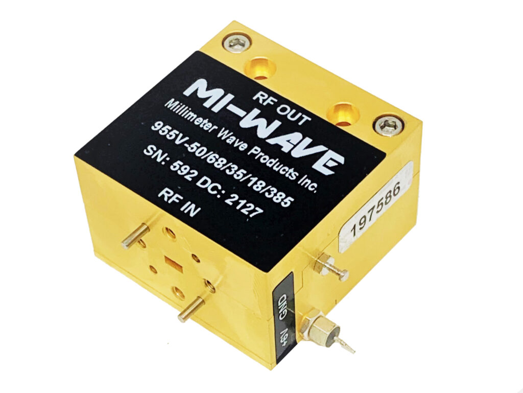
| 955V-50/68/35/18/385 | V-Band Low Noise Amplfier | 50 | 68 | 35 | 18 | WR-15 Waveguide, UG-385/U Flange | +6V | |||
| 955VF-35/15/385 | V-Band Low Noise Amplfier | 50 | 75 | 35 | 18 | WR-15 Waveguide, UG-385/U Flange | +6V | |||
| 955VF-35/13/1.85mmF | V-Band Low Noise Amplfier | 50 | 75 | 35 | 5 | 13 | 1.85mm Female Coaxial Connector | +6V | ||
| 955VF-20/15/385 | V-Band Low Noise Amplfier | 50 | 75 | 20 | 5 | 15 | WR-15 Waveguide, UG-385/U Flange | +6V | ||
| 955VF-30/10/385 | V-Band Low Noise Amplfier | 50 | 75 | 30 | 5 | 10 | WR-15 Waveguide, UG-385/U Flange | +6V | ||
| 955VF-40/385 | V-Band Low Noise Amplfier | 50 | 75 | 40 | 5 | 9 | WR-15 Waveguide, UG-385/U Flange | +6-+8V | ||
| 955EF-15/8/387 | E-band Low Noise Amplifier | 60 | 90 | 15 | 4.5 | 8 | WR-12 Waveguide, UG-387/U Flange | +8V | ||
| 955EF-20/10/387 | E-band Low Noise Amplifier | 60 | 90 | 20 | 5.5 | 10 | WR-12 Waveguide, UG-387/U Flange | +8V | ||
| 955EF-20/12/387 | E-band Low Noise Amplifier | 60 | 90 | 20 | 5 | 12 | WR-12 Waveguide, UG-387/U Flange | +8V | ||
| 955EF-25/8/387 | E-band Low Noise Amplifier | 60 | 90 | 25 | 4.5 | 8 | WR-12 Waveguide, UG-387/U Flange | +8V | ||
| 955EF-30/8/387 | E-band Low Noise Amplifier | 60 | 90 | 30 | 4.5 | 8 | WR-12 Waveguide, UG-387/U Flange | +8V | ||
| 955E-77/30/387 | E-band Low Noise Amplifier | 72 | 82 | 30 | 4 | 14 | 8 | WR-12 Waveguide, UG-387/U Flange | +8V | |
| 955WF-10/10/387 | W-band Low Noise Amplifier | 75 | 110 | 10 | 5.5 | 10 | WR-10 Waveguide, UG-387/U-M Flanges | +8V | ||
| 955WF-20/10/387 | W-band Low Noise Amplifier | 75 | 110 | 20 | 5.5 | 10 | WR-10 Waveguide, UG-387/U-M Flanges | +8V | ||
| 955WF-20/11.5/387H | W-band Low Noise Amplifier | 75 | 110 | 20 | 12 | 10 | WR-10 Waveguide, UG-387/U-M Flanges | +8V | ||
| 955WF-25/10/387 | W-band Low Noise Amplifier | 75 | 110 | 25 | 5.5 | 10 | WR-10 Waveguide, UG-387/U-M Flanges | +8V | ||
| 955WF-30/387 | W-band Low Noise Amplifier | 75 | 110 | 30 | 3 | 10 | WR-10 Waveguide, UG-387/U-M Flanges | +8V | ||
| 955WF-35/10/387 | W-band Low Noise Amplifier | 75 | 110 | 35 | 5 | 10 | WR-10 Waveguide, UG-387/U-M Flanges | +8V |
How Low Noise Amplifiers Work & How to Select the Right LNA
Low Noise Amplifiers (LNAs) are designed to amplify extremely weak RF, microwave, and millimeter-wave signals while adding as little additional noise as possible to the signal path. LNAs are commonly used at the front end of receiver systems where preserving signal integrity and maximizing receiver sensitivity are critical to overall system performance.
Because signals received by antennas are often extremely small, especially in long-range communication, radar, satellite, or sensing systems, the first amplifier stage plays a major role in determining how effectively the system can process weak incoming signals. A properly designed LNA improves signal strength before additional losses occur through filters, mixers, switches, cables, or waveguide components.
How Low Noise Amplifiers Work
An LNA works by taking a weak incoming RF signal and increasing its amplitude using active semiconductor devices powered by a DC bias supply. Unlike high power amplifiers that prioritize output power, LNAs are specifically optimized to minimize internally generated electrical noise while maintaining stable gain and low reflection characteristics.
The amplifier uses carefully designed matching networks, low-noise active devices, bias circuits, and filtering structures to maintain signal quality across the operating frequency range. Since any noise added at the beginning of the receiver chain becomes amplified by later stages, minimizing front-end noise is one of the most important aspects of receiver system design.
LNAs are typically installed as close to the antenna or receiver input as possible. This placement helps amplify the signal before losses from waveguides, cables, filters, or switching networks degrade the signal-to-noise ratio.
At microwave and millimeter-wave frequencies, even small insertion losses ahead of the LNA can significantly increase the overall system noise figure. For this reason, engineers often use low-loss waveguide components, short transmission paths, and carefully matched interfaces when integrating LNAs into high-frequency systems.
Key LNA Performance Parameters
Several important specifications determine how effectively an LNA will perform within a receiver architecture.
Noise Figure (NF): Noise figure measures how much additional noise the amplifier contributes to the signal path. Lower noise figure improves receiver sensitivity and weak signal detection capability.
Gain: Gain determines how much the signal is amplified between the input and output. Proper gain helps overcome downstream losses while maintaining system stability.
Frequency Range: Defines the operating bandwidth where the amplifier maintains specified gain, noise figure, and VSWR performance.
Gain Flatness: Describes how consistently gain is maintained across the frequency band.
Linearity: Determines how accurately the amplifier reproduces incoming signals without distortion, especially in environments with strong nearby signals.
VSWR & Impedance Matching: Proper matching minimizes reflections and helps maintain stable low-noise performance.
Stability: LNA stability is critical to prevent oscillations and unwanted behavior across the operating frequency range.
How to Select the Right Low Noise Amplifier
Selecting the correct LNA requires balancing noise figure, gain, bandwidth, linearity, RF interfaces, and environmental requirements to match the overall receiver architecture and application goals.
Prioritize Noise Figure
Noise figure is often the most important specification when selecting an LNA. Because the first amplifier stage dominates the overall receiver noise performance, reducing added noise helps maximize sensitivity and improve the ability to detect weak signals.
Even small losses ahead of the LNA can significantly degrade system noise figure, which is why minimizing front-end insertion loss is critical in many receiver systems.
Determine Required Gain
The amplifier should provide enough gain to overcome losses from downstream components such as mixers, filters, switches, cables, waveguide sections, and diplexers.
Too little gain may reduce receiver sensitivity, while excessive gain can create instability, compression, or unnecessary system noise amplification.
Verify Frequency Coverage
The LNA must maintain stable performance across the intended operating frequency range. Engineers should verify noise figure, gain flatness, and impedance matching throughout the full operating band.
Broadband systems may require wider operating bandwidths, while narrowband systems may prioritize optimized low-noise performance over a smaller frequency range.
Evaluate Linearity Requirements
Some RF environments contain strong nearby signals that can overload or compress the amplifier. In these situations, improved linearity and higher compression performance may be required to prevent distortion, intermodulation products, or receiver desensitization.
Review RF Interface Requirements
LNAs are available with a variety of RF interfaces depending on operating frequency and application requirements, including coaxial connectors and waveguide interfaces.
Proper impedance matching and low-loss integration are especially important in low-noise receiver systems.
Consider Environmental Conditions
Environmental factors such as vibration, airborne operation, outdoor deployment, temperature extremes, and continuous operation may influence amplifier selection and packaging requirements.
System-Level Receiver Considerations
LNA selection should always be evaluated as part of the complete receiver architecture rather than as an isolated component decision. Noise figure, gain distribution, filtering, switching, thermal performance, and RF interfaces all interact to determine total receiver performance.
By carefully evaluating these parameters, engineers can select an LNA that improves receiver sensitivity, preserves signal integrity, and maintains reliable operation across demanding RF, microwave, and millimeter-wave applications.
Key Features & Performance Benefits
Wide Frequency Coverage
Supports microwave and millimeter-wave frequency bands with LNA configurations tailored to specific receiver front-end and system requirements.
Low Noise Figure Performance
Designed to minimize added noise and preserve signal-to-noise ratio, improving receiver sensitivity in low-level and long-range signal environments.
Stable Gain and Gain Flatness
Provides consistent gain across the operating band, supporting predictable receiver performance and simplified system calibration.
High Linearity for Receiver Chains
Optimized to handle strong in-band and adjacent-band signals with reduced distortion, helping prevent desensitization and intermodulation effects.
Excellent Input and Output Matching
Carefully matched input and output interfaces reduce reflections and improve stability when integrated into complex RF signal chains.
Clean Spectral Behavior
Low spurious responses and controlled nonlinear behavior help maintain spectral purity and minimize interference in sensitive receive systems.
Flexible System Integration
Compatible with filters, mixers, frequency converters, and downstream amplification stages for modular and scalable receiver architectures.
Thermally Stable Operation
Engineered for reliable performance over extended operating periods, with biasing and thermal considerations that support continuous operation.
Multiple Packaging Options
Available in configurations suitable for laboratory use, system-level integration, and demanding commercial or defense-grade platforms.
Low Noise Amplifier (LNA) Calculators
These calculators support LNA and receiver front-end planning, including noise floor estimation, receiver sensitivity, cascaded noise figure (Friis), output level estimates, and noise figure to equivalent noise temperature conversion for RF, microwave, and millimeter-wave systems.
Jump to: Noise Floor · Receiver Sensitivity · Cascade NF (Friis) · Output Level · NF ↔ Noise Temperature · Return Loss ↔ VSWR
1) Noise Floor Calculator (−174 dBm/Hz + 10·log10(BW) + NF)
Estimate receiver noise floor over a bandwidth using thermal noise density (−174 dBm/Hz at 290 K) and noise figure.
2) Receiver Sensitivity (Noise Floor + Required SNR)
Estimate minimum detectable signal (MDS) or receiver sensitivity using noise floor and required SNR margin.
3) Cascaded Noise Figure (Friis) + Total Gain
Estimate total gain and cascaded noise figure using Friis. Enter up to 4 stages (LNA, filter, converter, IF amp).
4) LNA Output Level (Pin + Gain − Loss)
Estimate LNA output level from input power and gain. Add loss for any interconnect or inline attenuation.
5) NF ↔ Equivalent Noise Temperature (Te)
Convert noise figure to equivalent input noise temperature (Te). Uses reference temperature T0 = 290 K.
6) Return Loss ↔ VSWR Converter
Convert return loss (dB) to VSWR or VSWR to return loss. Useful for spec writing and datasheet summaries.
Typical Applications for Microwave & Millimeter-Wave Low Noise Amplifiers
Mi-Wave 955 Series microwave and millimeter-wave low noise amplifiers (LNAs) are used in a wide range of receiver, signal conditioning, and system-integration applications where preserving signal-to-noise ratio (SNR), minimizing system noise floor, and maintaining stable gain are critical.
Satellite Communication (SatCom)
Low noise amplifiers play a critical role in satellite downlink and receive chains, where weak signals must be amplified with minimal added noise.
Common SatCom applications include:
-
Satellite downlink receiver chains
-
VSAT and gateway terminal receivers
-
Ground station and teleport infrastructure
-
Integration with low-loss front-end filters and frequency converters
-
High-throughput satellite (HTS) receive systems
Low noise figure and stable gain improve receiver sensitivity and link margin in space-to-ground communications.
Radar and Sensing Systems
In radar platforms, LNAs are typically used at the front end of the receiver to amplify low-level return signals prior to detection and processing.
Typical radar applications include:
-
Surveillance and tracking radar receivers
-
FMCW and pulse-Doppler radar systems
-
Ground-based, airborne, and maritime radar platforms
-
Radar receiver calibration and signal conditioning
Consistent gain, low noise figure, and good matching improve detection sensitivity and target discrimination.
Point-to-Point Microwave and Millimeter-Wave Links
LNAs support high-frequency wireless links by improving receiver performance in long-distance and high-capacity systems.
Applications include:
-
Microwave and mmWave backhaul receivers
-
Fixed wireless access (FWA) systems
-
Private and critical infrastructure networks
-
High-throughput point-to-point radio links
Low noise amplification helps maintain link margin and reliable data throughput under varying conditions.
5G and Millimeter-Wave Wireless Development
Microwave and mmWave LNAs are widely used in the development, testing, and validation of next-generation wireless systems, particularly at FR2 frequencies.
Applications include:
-
5G FR2 base station and small-cell receiver testing
-
mmWave receiver and front-end development
-
Beamforming and MIMO system validation
-
Wireless access and backhaul research platforms
Low noise and stable gain are essential for accurate EVM measurements and receiver characterization.
RF Test, Measurement, and Research
In laboratory, production, and research environments, LNAs are used to amplify low-level signals with predictable performance.
Typical uses include:
-
RF and mmWave test benches
-
Receiver sensitivity measurements
-
Device and subsystem characterization
-
Automated test equipment (ATE) and validation systems
Repeatable noise and gain performance support accurate measurement and verification workflows.
Low Noise Amplifier (LNA) FAQ
These quick answers cover Low Noise Amplifiers (LNAs) used in RF, microwave, and millimeter-wave systems, including satellite communications (SatCom), radar receivers, telemetry, radio astronomy, 5G/mmWave wireless, and RF test and measurement applications.
Quick Answers
What is an LNA?
A Low Noise Amplifier (LNA) is an RF amplifier designed to amplify very weak signals while adding as little noise as possible. LNAs are typically placed at the front end of a receiver chain to preserve signal quality and maximize system sensitivity.
Why is low noise figure important?
Noise figure determines how much noise an amplifier adds to a signal. A lower noise figure improves receiver sensitivity, increases detection range, and enhances performance in weak-signal systems such as satellite downlinks, radar receivers, and radio astronomy.
Where is an LNA used in an RF system?
LNAs are normally installed immediately after the antenna or input filter. Placing the LNA first minimizes system noise contribution and improves overall receiver noise figure.
What applications commonly use LNAs?
LNAs are widely used in satellite communications, radar systems, telemetry receivers, 5G/mmWave wireless, radio astronomy, and RF test and measurement systems.
More Technical Questions
What is noise figure and how is it measured?
What is the difference between an LNA and a standard RF amplifier?
What gain is typical for an LNA?
How does an LNA affect system noise figure?
What frequency bands do LNAs support?
Why is input matching important for LNAs?
Are LNAs used in SatCom and radar systems?
Glossary of Low Noise Amplifier (LNA) Terms
Core LNA Definitions
Low Noise Amplifier (LNA)
An RF amplifier designed to amplify very weak input signals while introducing the minimum possible additional noise. LNAs are typically the first active component in a receiver chain and play a critical role in determining overall system sensitivity.
Receiver Front End
The portion of an RF receiver that processes incoming signals directly after the antenna. This stage often includes an input filter followed by an LNA to preserve signal integrity before frequency conversion.
System Noise Figure
A measure of the total noise added by a receiver system. Because the LNA is first in the signal chain, its noise figure dominates the overall system noise performance.
Noise and Sensitivity Terms
Noise Figure (NF)
A measure of how much noise an amplifier adds to a signal, expressed in decibels (dB). Lower noise figure values indicate better performance. LNAs for sensitive applications often achieve noise figures below 3 dB.
Equivalent Noise Temperature
An alternative way to express noise performance, representing the noise contribution of the LNA as an equivalent temperature. Commonly used in satellite communications and radio astronomy.
Receiver Sensitivity
The minimum input signal level a receiver can reliably detect. Lower noise figure LNAs improve sensitivity, allowing detection of weaker signals.
Gain and Linearity Terms
Small Signal Gain
The amplification provided by an LNA when operating below compression. Typical LNA gain ranges from 15 to 40 dB depending on frequency band and application.
Gain Flatness
The variation in gain across the operating frequency band. Good gain flatness ensures consistent amplification over the entire bandwidth.
1 dB Compression Point (P1dB)
The input or output power level at which the amplifier gain compresses by 1 dB from its linear value. LNAs are generally operated well below this point to preserve linearity and noise performance.
Linearity
The ability of an LNA to amplify signals without distortion. High linearity reduces intermodulation products and improves performance in multi-signal or high-interference environments.
Matching and RF Interface Terms
Input Return Loss (S11)
A measure of how well the LNA input is impedance-matched to the source. Better return loss improves power transfer and noise performance.
Output Return Loss (S22)
A measure of impedance matching at the LNA output, affecting signal transfer to downstream components.
VSWR (Voltage Standing Wave Ratio)
A ratio that describes impedance matching quality. Lower VSWR values indicate better matching and reduced reflections.
RF Input Interface
The physical connection between the antenna or waveguide and the LNA. Common interfaces include SMA connectors and waveguide flanges such as WR-28, WR-15, and WR-10.
Stability and Protection Terms
Unconditional Stability
An LNA design condition where the amplifier remains stable for all source and load impedances across the operating frequency range.
Oscillation
Unwanted self-generated signals caused by instability. LNAs are carefully designed to prevent oscillations, especially at high gain levels.
Input Power Handling
The maximum RF input power the LNA can tolerate without damage or performance degradation. Critical in systems exposed to strong interferers.
Frequency and Bandwidth Terms
Operating Frequency Range
The RF frequency band over which the LNA meets specified performance requirements. LNAs are available from L-band through millimeter-wave bands including Ka-, Q-, V-, and W-band.
Instantaneous Bandwidth
The frequency span over which the LNA can amplify signals without retuning or performance degradation.
Wideband LNA
An LNA designed to operate over a broad frequency range, supporting multi-channel or frequency-agile systems.
Power and Biasing Terms
DC Bias Voltage
The supply voltage required to operate the LNA. Common values include 5 V, 12 V, and 28 V depending on design and application.
Bias Stability
The ability of the LNA bias circuitry to maintain consistent operating conditions over temperature and time, ensuring repeatable performance.
Current Consumption
The amount of DC current drawn by the LNA. Important for airborne, space, and battery-powered systems.
Application-Specific Terms
Low-Noise Block Downconverter (LNB)
A module that integrates an LNA with a downconverter to amplify and convert high-frequency RF signals to a lower IF or L-band output.
Satellite Communication (SatCom)
Communication systems that rely on LNAs to amplify weak downlink signals from satellites before frequency conversion and demodulation.
Radar Receiver
A system that uses LNAs to amplify reflected radar signals, improving detection range and target resolution.
Radio Astronomy
Scientific applications that depend on ultra-low-noise LNAs to detect extremely weak cosmic signals.
5G and mmWave Wireless
High-frequency wireless systems that use LNAs to improve receiver sensitivity in millimeter-wave bands.
System-Level Performance Terms
Dynamic Range
The range between the smallest and largest signals the LNA can process without excessive noise or distortion.
Intermodulation Products
Unwanted signals generated when multiple RF tones are amplified simultaneously. Good LNA linearity minimizes these effects.
Signal-to-Noise Ratio (SNR)
The ratio of desired signal power to noise power at the LNA output. LNAs are designed to maximize SNR at the receiver input.


Interested in this product or other Mi-Wave solutions?
Contact our team to discuss your frequency range, interface needs, and application requirements.
Custom configurations are available for specialized RF, microwave, and millimeter-wave systems.
Return to Low Noise Amplifers Page
Return to Amplifiers
Return to Products Page