
Product Description
Mi-Wave’s 955 Series microwave and millimeter-wave E-band low noise amplifiers are designed for high-frequency receiver systems requiring low noise, high gain, and stable performance across defined E-band spectrum allocations. These LNAs support demanding applications in laboratory, fielded, and production environments where receiver sensitivity and output power capability are critical.
A representative model in the series is the 955E-77/30/387 E-band Low Noise Amplifier, operating over a 72 GHz to 82 GHz frequency range, covering a key portion of the E-band used in high-capacity wireless links, satellite communications, and radar systems. This amplifier delivers 30 dB typical small-signal gain, with typical performance of approximately 32 dB across the band, while maintaining a 4 dB typical noise figure. The amplifier also provides +14 dBm typical saturated output power, enabling robust signal handling in E-band receiver front ends.
As the first active stage in millimeter-wave receive chains, E-band low noise amplifiers play a decisive role in overall system noise figure and dynamic range. The 955E-77/30/387 incorporates regulated biasing and a robust thermal design to ensure stable, repeatable operation under varying conditions. When operated at saturation for extended durations, additional heat sinking may be recommended to support long-term reliability in demanding E-band millimeter-wave applications
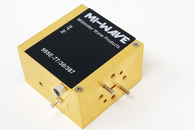
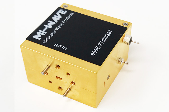
*Actual product may be different from the image shown per customers specifcations
*All data presented is collected from a sample lot.
* Actual data may vary unit to unit, slightly.
*All testing was performed under +25 °C case temperature.
*Consult factory to confirm if material, plating, size, shape, orientation and any electrical parameter is critical for the application as website information is for reference only.
*Millimeter Wave Products, Inc. reserves the right to change the information presented on website without notice as we continue to enhance the performance and design of our products.
Specifications
| Parameter | Specification |
|---|---|
| Frequency Range | 72 GHz to 82 GHz |
| Band | E-band |
| Small Signal Gain | 30 dB typical |
| Noise Figure | 4 dB typical |
| Output Power @ Psat | +14 dBm typical |
| Output P1dB | +11 dBm typical |
| Bias Voltage | +5 V to +8 V (typically +5 V) |
| DC Current | Approximately 160 mA |
| Maximum RF Input Power (CW) | 0 dBm |
| Configuration | Low Noise Amplifier (LNA) |
| Series | 955 Series |
| Operating Temperature | Case temperature not to exceed +60 °C |
| Thermal Note | Additional heat sink may be required at sustained saturation |
Low Noise Amplifier (LNA) Calculators
These calculators support LNA and receiver front-end planning, including noise floor estimation, receiver sensitivity, cascaded noise figure (Friis), output level estimates, and noise figure to equivalent noise temperature conversion for RF, microwave, and millimeter-wave systems.
Jump to: Noise Floor · Receiver Sensitivity · Cascade NF (Friis) · Output Level · NF ↔ Noise Temperature · Return Loss ↔ VSWR
1) Noise Floor Calculator (−174 dBm/Hz + 10·log10(BW) + NF)
Estimate receiver noise floor over a bandwidth using thermal noise density (−174 dBm/Hz at 290 K) and noise figure.
2) Receiver Sensitivity (Noise Floor + Required SNR)
Estimate minimum detectable signal (MDS) or receiver sensitivity using noise floor and required SNR margin.
3) Cascaded Noise Figure (Friis) + Total Gain
Estimate total gain and cascaded noise figure using Friis. Enter up to 4 stages (LNA, filter, converter, IF amp).
4) LNA Output Level (Pin + Gain − Loss)
Estimate LNA output level from input power and gain. Add loss for any interconnect or inline attenuation.
5) NF ↔ Equivalent Noise Temperature (Te)
Convert noise figure to equivalent input noise temperature (Te). Uses reference temperature T0 = 290 K.
6) Return Loss ↔ VSWR Converter
Convert return loss (dB) to VSWR or VSWR to return loss. Useful for spec writing and datasheet summaries.
Key Features & Performance Benefits
Wide Frequency Coverage
Supports microwave and millimeter-wave frequency bands with LNA configurations tailored to specific receiver front-end and system requirements.
Low Noise Figure Performance
Designed to minimize added noise and preserve signal-to-noise ratio, improving receiver sensitivity in low-level and long-range signal environments.
Stable Gain and Gain Flatness
Provides consistent gain across the operating band, supporting predictable receiver performance and simplified system calibration.
High Linearity for Receiver Chains
Optimized to handle strong in-band and adjacent-band signals with reduced distortion, helping prevent desensitization and intermodulation effects.
Excellent Input and Output Matching
Carefully matched input and output interfaces reduce reflections and improve stability when integrated into complex RF signal chains.
Clean Spectral Behavior
Low spurious responses and controlled nonlinear behavior help maintain spectral purity and minimize interference in sensitive receive systems.
Flexible System Integration
Compatible with filters, mixers, frequency converters, and downstream amplification stages for modular and scalable receiver architectures.
Thermally Stable Operation
Engineered for reliable performance over extended operating periods, with biasing and thermal considerations that support continuous operation.
Multiple Packaging Options
Available in configurations suitable for laboratory use, system-level integration, and demanding commercial or defense-grade platforms.
Typical Applications for Microwave & Millimeter-Wave Low Noise Amplifiers
Mi-Wave 955 Series microwave and millimeter-wave low noise amplifiers (LNAs) are used in a wide range of receiver, signal conditioning, and system-integration applications where preserving signal-to-noise ratio (SNR), minimizing system noise floor, and maintaining stable gain are critical.
Satellite Communication (SatCom)
Low noise amplifiers play a critical role in satellite downlink and receive chains, where weak signals must be amplified with minimal added noise.
Common SatCom applications include:
-
Satellite downlink receiver chains
-
VSAT and gateway terminal receivers
-
Ground station and teleport infrastructure
-
Integration with low-loss front-end filters and frequency converters
-
High-throughput satellite (HTS) receive systems
Low noise figure and stable gain improve receiver sensitivity and link margin in space-to-ground communications.
Radar and Sensing Systems
In radar platforms, LNAs are typically used at the front end of the receiver to amplify low-level return signals prior to detection and processing.
Typical radar applications include:
-
Surveillance and tracking radar receivers
-
FMCW and pulse-Doppler radar systems
-
Ground-based, airborne, and maritime radar platforms
-
Radar receiver calibration and signal conditioning
Consistent gain, low noise figure, and good matching improve detection sensitivity and target discrimination.
Point-to-Point Microwave and Millimeter-Wave Links
LNAs support high-frequency wireless links by improving receiver performance in long-distance and high-capacity systems.
Applications include:
-
Microwave and mmWave backhaul receivers
-
Fixed wireless access (FWA) systems
-
Private and critical infrastructure networks
-
High-throughput point-to-point radio links
Low noise amplification helps maintain link margin and reliable data throughput under varying conditions.
5G and Millimeter-Wave Wireless Development
Microwave and mmWave LNAs are widely used in the development, testing, and validation of next-generation wireless systems, particularly at FR2 frequencies.
Applications include:
-
5G FR2 base station and small-cell receiver testing
-
mmWave receiver and front-end development
-
Beamforming and MIMO system validation
-
Wireless access and backhaul research platforms
Low noise and stable gain are essential for accurate EVM measurements and receiver characterization.
RF Test, Measurement, and Research
In laboratory, production, and research environments, LNAs are used to amplify low-level signals with predictable performance.
Typical uses include:
-
RF and mmWave test benches
-
Receiver sensitivity measurements
-
Device and subsystem characterization
-
Automated test equipment (ATE) and validation systems
Repeatable noise and gain performance support accurate measurement and verification workflows.
Low Noise Amplifier (LNA) FAQ
These quick answers cover Low Noise Amplifiers (LNAs) used in RF, microwave, and millimeter-wave systems, including satellite communications (SatCom), radar receivers, telemetry, radio astronomy, 5G/mmWave wireless, and RF test and measurement applications.
Quick Answers
What is an LNA?
A Low Noise Amplifier (LNA) is an RF amplifier designed to amplify very weak signals while adding as little noise as possible. LNAs are typically placed at the front end of a receiver chain to preserve signal quality and maximize system sensitivity.
Why is low noise figure important?
Noise figure determines how much noise an amplifier adds to a signal. A lower noise figure improves receiver sensitivity, increases detection range, and enhances performance in weak-signal systems such as satellite downlinks, radar receivers, and radio astronomy.
Where is an LNA used in an RF system?
LNAs are normally installed immediately after the antenna or input filter. Placing the LNA first minimizes system noise contribution and improves overall receiver noise figure.
What applications commonly use LNAs?
LNAs are widely used in satellite communications, radar systems, telemetry receivers, 5G/mmWave wireless, radio astronomy, and RF test and measurement systems.
More Technical Questions
What is noise figure and how is it measured?
What is the difference between an LNA and a standard RF amplifier?
What gain is typical for an LNA?
How does an LNA affect system noise figure?
What frequency bands do LNAs support?
Why is input matching important for LNAs?
Are LNAs used in SatCom and radar systems?
Glossary of Low Noise Amplifier (LNA) Terms
Core LNA Definitions
Low Noise Amplifier (LNA)
An RF amplifier designed to amplify very weak input signals while introducing the minimum possible additional noise. LNAs are typically the first active component in a receiver chain and play a critical role in determining overall system sensitivity.
Receiver Front End
The portion of an RF receiver that processes incoming signals directly after the antenna. This stage often includes an input filter followed by an LNA to preserve signal integrity before frequency conversion.
System Noise Figure
A measure of the total noise added by a receiver system. Because the LNA is first in the signal chain, its noise figure dominates the overall system noise performance.
Noise and Sensitivity Terms
Noise Figure (NF)
A measure of how much noise an amplifier adds to a signal, expressed in decibels (dB). Lower noise figure values indicate better performance. LNAs for sensitive applications often achieve noise figures below 3 dB.
Equivalent Noise Temperature
An alternative way to express noise performance, representing the noise contribution of the LNA as an equivalent temperature. Commonly used in satellite communications and radio astronomy.
Receiver Sensitivity
The minimum input signal level a receiver can reliably detect. Lower noise figure LNAs improve sensitivity, allowing detection of weaker signals.
Gain and Linearity Terms
Small Signal Gain
The amplification provided by an LNA when operating below compression. Typical LNA gain ranges from 15 to 40 dB depending on frequency band and application.
Gain Flatness
The variation in gain across the operating frequency band. Good gain flatness ensures consistent amplification over the entire bandwidth.
1 dB Compression Point (P1dB)
The input or output power level at which the amplifier gain compresses by 1 dB from its linear value. LNAs are generally operated well below this point to preserve linearity and noise performance.
Linearity
The ability of an LNA to amplify signals without distortion. High linearity reduces intermodulation products and improves performance in multi-signal or high-interference environments.
Matching and RF Interface Terms
Input Return Loss (S11)
A measure of how well the LNA input is impedance-matched to the source. Better return loss improves power transfer and noise performance.
Output Return Loss (S22)
A measure of impedance matching at the LNA output, affecting signal transfer to downstream components.
VSWR (Voltage Standing Wave Ratio)
A ratio that describes impedance matching quality. Lower VSWR values indicate better matching and reduced reflections.
RF Input Interface
The physical connection between the antenna or waveguide and the LNA. Common interfaces include SMA connectors and waveguide flanges such as WR-28, WR-15, and WR-10.
Stability and Protection Terms
Unconditional Stability
An LNA design condition where the amplifier remains stable for all source and load impedances across the operating frequency range.
Oscillation
Unwanted self-generated signals caused by instability. LNAs are carefully designed to prevent oscillations, especially at high gain levels.
Input Power Handling
The maximum RF input power the LNA can tolerate without damage or performance degradation. Critical in systems exposed to strong interferers.
Frequency and Bandwidth Terms
Operating Frequency Range
The RF frequency band over which the LNA meets specified performance requirements. LNAs are available from L-band through millimeter-wave bands including Ka-, Q-, V-, and W-band.
Instantaneous Bandwidth
The frequency span over which the LNA can amplify signals without retuning or performance degradation.
Wideband LNA
An LNA designed to operate over a broad frequency range, supporting multi-channel or frequency-agile systems.
Power and Biasing Terms
DC Bias Voltage
The supply voltage required to operate the LNA. Common values include 5 V, 12 V, and 28 V depending on design and application.
Bias Stability
The ability of the LNA bias circuitry to maintain consistent operating conditions over temperature and time, ensuring repeatable performance.
Current Consumption
The amount of DC current drawn by the LNA. Important for airborne, space, and battery-powered systems.
Application-Specific Terms
Low-Noise Block Downconverter (LNB)
A module that integrates an LNA with a downconverter to amplify and convert high-frequency RF signals to a lower IF or L-band output.
Satellite Communication (SatCom)
Communication systems that rely on LNAs to amplify weak downlink signals from satellites before frequency conversion and demodulation.
Radar Receiver
A system that uses LNAs to amplify reflected radar signals, improving detection range and target resolution.
Radio Astronomy
Scientific applications that depend on ultra-low-noise LNAs to detect extremely weak cosmic signals.
5G and mmWave Wireless
High-frequency wireless systems that use LNAs to improve receiver sensitivity in millimeter-wave bands.
System-Level Performance Terms
Dynamic Range
The range between the smallest and largest signals the LNA can process without excessive noise or distortion.
Intermodulation Products
Unwanted signals generated when multiple RF tones are amplified simultaneously. Good LNA linearity minimizes these effects.
Signal-to-Noise Ratio (SNR)
The ratio of desired signal power to noise power at the LNA output. LNAs are designed to maximize SNR at the receiver input.
| MIWV P/N | Description | Low Frequency (GHz) | High Frequency (GHz) | Gain (dB) | Noise Figure (dB) | Output Power Psat (dBm) | Output Power P1dB (dBm) | Input/Output Port | DC Bias | LINK |
|---|---|---|---|---|---|---|---|---|---|---|
| 955-01/60/30/1.85mmF | DC - 60GHz Low Noise Amplifier | 1 | 60 | 30 | 5 | 12 | 10 | 1.85 mm Female Coaxial Connector | +8V | |
| 955AF-20/599 | Ka-band Low Noise Amplifier | 26.5 | 40 | 20 | 3.5 | WR-28 waveguide, UG-599/U Flange | ||||
| 955AF-20/10/KF | Ka-band Low Noise Amplifier | 26.5 | 40 | 20 | 3 | 10 | 2.92mm K Female Coaxial Connector | +8V | ||
| 955AF-30/18/599H | Ka-band Low Noise Amplifier | 26.5 | 40 | 30 | 3 | 18 | WR-28 waveguide, UG-599/U Flange | +8V | ||
| 955AF-40/10/2.4mmF | Ka-band Low Noise Amplifier | 26.5 | 40 | 40 | 4.5 | 10 | 2.4mm Female Coaxial Connector | +8V | ||
| 955BF-15/8/383 | B-band Low Noise Amplifier | 33 | 50 | 10-15 | 5.5 | 8 | WR-22 Waveguide with UG-383/U Flanges | +8-12V | ||
| 955BF-20/10/383 | B-band Low Noise Amplifier | 33 | 50 | 20 | 5.5 | 10 | WR-22 Waveguide with UG-383/U Flanges | +8V | ||
| 955BF-30/10/383 | B-band Low Noise Amplifier | 33 | 50 | 30 | 5.5 | 10 | WR-22 Waveguide with UG-383/U Flanges | +8V | ||
| 955BF-40/10/383 | B-band Low Noise Amplifier | 33 | 50 | 40 | 6 | 10 | WR-22 Waveguide with UG-383/U Flanges | +8V | ||
| 955UF-15/10/383 | U-band Low Noise Amplifier | 40 | 60 | 15 | 5 | 10 | WR-19 Waveguide, UG-383/U-M Flange | +12-15V | ||
| 955UF-20/10/383 | U-band Low Noise Amplifier | 40 | 60 | 20 | 5 | 10 | WR-19 Waveguide, UG-383/U-M Flange | +8V | ||
| 955UF-30/15/383 | U-band Low Noise Amplifier | 40 | 60 | 30 | 4.5 | 15 | WR-19 Waveguide, UG-383/U-M Flange | +6V | ||
| 955UF-30/383 | U-band Low Noise Amplifier | 40 | 60 | 30 | 5 | 15 | WR-19 Waveguide, UG-383/U-M Flange | +6V | ||
| 955UF-40/13/383 | U-band Low Noise Amplifier | 40 | 60 | 40 | 5 | 13 | WR-19 Waveguide, UG-383/U-M Flange | +6V | ||
| 955U-50/66/22/15/383 | U-band Low Noise Amplifier | 50 | 66 | 22 | 5 | 22 | WR-19 Waveguide, UG-383/U-M Flange | +6V | ||
| 955V-50/68/35/18/385 | V-Band Low Noise Amplfier | 50 | 68 | 35 | 18 | WR-15 Waveguide, UG-385/U Flange | +6V | |||
| 955VF-35/15/385 | V-Band Low Noise Amplfier | 50 | 75 | 35 | 18 | WR-15 Waveguide, UG-385/U Flange | +6V | |||
| 955VF-35/13/1.85mmF | V-Band Low Noise Amplfier | 50 | 75 | 35 | 5 | 13 | 1.85mm Female Coaxial Connector | +6V | ||
| 955VF-20/15/385 | V-Band Low Noise Amplfier | 50 | 75 | 20 | 5 | 15 | WR-15 Waveguide, UG-385/U Flange | +6V | ||
| 955VF-30/10/385 | V-Band Low Noise Amplfier | 50 | 75 | 30 | 5 | 10 | WR-15 Waveguide, UG-385/U Flange | +6V | ||
| 955VF-40/385 | V-Band Low Noise Amplfier | 50 | 75 | 40 | 5 | 9 | WR-15 Waveguide, UG-385/U Flange | +6-+8V | ||
| 955EF-15/8/387 | E-band Low Noise Amplifier | 60 | 90 | 15 | 4.5 | 8 | WR-12 Waveguide, UG-387/U Flange | +8V | ||
| 955EF-20/10/387 | E-band Low Noise Amplifier | 60 | 90 | 20 | 5.5 | 10 | WR-12 Waveguide, UG-387/U Flange | +8V | ||
| 955EF-20/12/387 | E-band Low Noise Amplifier | 60 | 90 | 20 | 5 | 12 | WR-12 Waveguide, UG-387/U Flange | +8V | ||
| 955EF-25/8/387 | E-band Low Noise Amplifier | 60 | 90 | 25 | 4.5 | 8 | WR-12 Waveguide, UG-387/U Flange | +8V | ||
| 955EF-30/8/387 | E-band Low Noise Amplifier | 60 | 90 | 30 | 4.5 | 8 | WR-12 Waveguide, UG-387/U Flange | +8V | ||
| 955E-77/30/387 | E-band Low Noise Amplifier | 72 | 82 | 30 | 4 | 14 | 8 | WR-12 Waveguide, UG-387/U Flange | +8V | |
| 955WF-10/10/387 | W-band Low Noise Amplifier | 75 | 110 | 10 | 5.5 | 10 | WR-10 Waveguide, UG-387/U-M Flanges | +8V | ||
| 955WF-20/10/387 | W-band Low Noise Amplifier | 75 | 110 | 20 | 5.5 | 10 | WR-10 Waveguide, UG-387/U-M Flanges | +8V | ||
| 955WF-20/11.5/387H | W-band Low Noise Amplifier | 75 | 110 | 20 | 12 | 10 | WR-10 Waveguide, UG-387/U-M Flanges | +8V | ||
| 955WF-25/10/387 | W-band Low Noise Amplifier | 75 | 110 | 25 | 5.5 | 10 | WR-10 Waveguide, UG-387/U-M Flanges | +8V | ||
| 955WF-30/387 | W-band Low Noise Amplifier | 75 | 110 | 30 | 3 | 10 | WR-10 Waveguide, UG-387/U-M Flanges | +8V | ||
| 955WF-35/10/387 | W-band Low Noise Amplifier | 75 | 110 | 35 | 5 | 10 | WR-10 Waveguide, UG-387/U-M Flanges | +8V |
RF and Microwave Low Noise Amplifiers
Low Noise Amplifiers: RF and Microwave Systems
RF and microwave low noise amplifiers (LNAs) are critical components in modern RF, microwave, and millimeter-wave systems. Their primary role is to amplify extremely weak input signals while adding as little noise as possible, preserving signal-to-noise ratio (SNR), phase integrity, and spectral fidelity across high-frequency receive applications.
Low noise amplifiers are widely used in satellite communications, radar systems, point-to-point microwave links, telemetry, electronic warfare, 5G and millimeter-wave wireless, scientific research, and RF test and measurement environments, where receiver sensitivity, noise performance, and gain stability are essential.
RF Low Noise Amplifiers
An RF low noise amplifier is typically the first active stage in a receiver chain, amplifying low-level RF signals captured by an antenna or front-end filter before downstream processing. LNAs are designed to operate across a wide range of frequencies, from X-band and Ku-band through Ka-band, Q-band, V-band, and W-band, with noise figure, gain, and bandwidth optimized for the target application.
Key performance characteristics of RF and microwave low noise amplifiers include:
-
Noise figure and noise temperature
-
Small signal gain and gain flatness across frequency
-
Linearity and compression performance (P1dB, IP3)
-
Input and output return loss
-
Stability and phase performance
These parameters directly influence receiver sensitivity, dynamic range, and overall system performance.
Microwave and Millimeter-Wave Low Noise Amplifiers
Microwave and millimeter-wave low noise amplifiers operate at frequencies where device noise, impedance matching, and packaging losses become critical design considerations. These amplifiers are commonly implemented using GaAs, InP, or advanced GaN semiconductor technologies, selected to achieve optimal noise performance, gain, and stability across wide bandwidths.
Millimeter-wave LNAs are essential in systems operating at Ka-, Q-, V-, and W-band, supporting applications such as satellite downlinks, radar receivers, radio astronomy, and emerging mmWave wireless technologies.
Low-Noise and Wideband Amplifier Architectures
Low noise amplifiers are available in multiple architectures to meet different system requirements:
-
Ultra-low-noise amplifiers optimized for minimum noise figure
-
Wideband LNAs supporting multi-octave or multi-band operation
-
High-linearity LNAs for strong-signal or congested RF environments
-
Cryogenic and specialty LNAs for scientific and research applications
The selection of LNA architecture depends on operating frequency, bandwidth, signal environment, and system noise budget.
Common Applications for RF and Microwave Low Noise Amplifiers
Satellite Communications
-
Satellite downlink receive chains
-
Ground stations and gateway receivers
-
Ku-, Ka-, Q-, and V-band satellite systems
Radar Systems
-
Radar receiver front ends
-
FMCW and pulse-Doppler radar receivers
-
Surveillance, tracking, and imaging radar
Point-to-Point Microwave and mmWave Links
-
Microwave and millimeter-wave receivers
-
Fixed wireless access systems
-
High-capacity data links
Telemetry and Aerospace
-
Flight test instrumentation
-
UAV and unmanned platform receivers
-
Space and defense telemetry systems
5G and Millimeter-Wave Wireless
-
5G FR2 receiver testing and validation
-
Beamforming and MIMO system development
-
mmWave access and backhaul research
RF Test and Measurement
-
Signal amplification for receiver test benches
-
Automated test equipment (ATE)
-
System noise figure and sensitivity characterization
Integration with RF Signal Chains
In a typical RF receive architecture, the low noise amplifier follows the antenna and input filtering, providing the first stage of amplification before frequency conversion or baseband processing. Because the LNA dominates the system noise figure, its placement, matching, and stability are critical to overall receiver performance.
LNAs are often integrated into custom RF subsystems, including receiver front ends, transceivers, radar modules, and multi-channel RF platforms.
Reliability, Thermal Management, and Packaging
RF and microwave low noise amplifiers are designed for operation in commercial, industrial, defense, airborne, and harsh environments. Robust mechanical packaging, stable bias control, and thermal design ensure consistent noise and gain performance across wide temperature ranges and operating conditions.
Packaging options include compact coaxial modules, waveguide assemblies, rack-mounted enclosures, and ruggedized housings, supporting both laboratory and fielded installations.
Role of Low Noise Amplifiers in RF Systems
Within an RF system, the low noise amplifier plays a decisive role in determining receiver sensitivity, link margin, and overall system noise performance. Excess noise, instability, or compression in the LNA stage directly degrades signal detection, demodulation accuracy, and system reliability.
By delivering stable, low-noise, and broadband amplification, RF and microwave low noise amplifiers enable reliable operation of modern communication, sensing, and test systems across microwave and millimeter-wave frequencies.
Build Your RF Low Noise Amplifier Needs and more!
With more than 35 years of experience in microwave and millimeter-wave RF engineering, our team designs and supports high-performance RF and microwave low noise amplifiers for demanding RF, microwave, and mmWave applications. Our capabilities span custom LNA design, prototyping, manufacturing, and system integration, enabling us to deliver reliable, production-ready low noise amplifier solutions tailored to specific frequency ranges, noise figure targets, gain requirements, linearity constraints, bandwidth needs, and thermal operating conditions.
Contact us to discuss RF low noise amplifiers, microwave and millimeter-wave LNAs, ultra-low-noise and wideband LNA architectures, high-linearity receiver front-end amplifiers, and custom RF and mmWave LNA sub-assemblies. Mi-Wave works closely with customers to ensure optimal receiver sensitivity, stable gain performance, noise figure control, thermal reliability, and seamless integration into advanced communication, radar, telemetry, wireless, and test and measurement systems.