
Products> Antenna Products > Adjustable Circular Polarizers
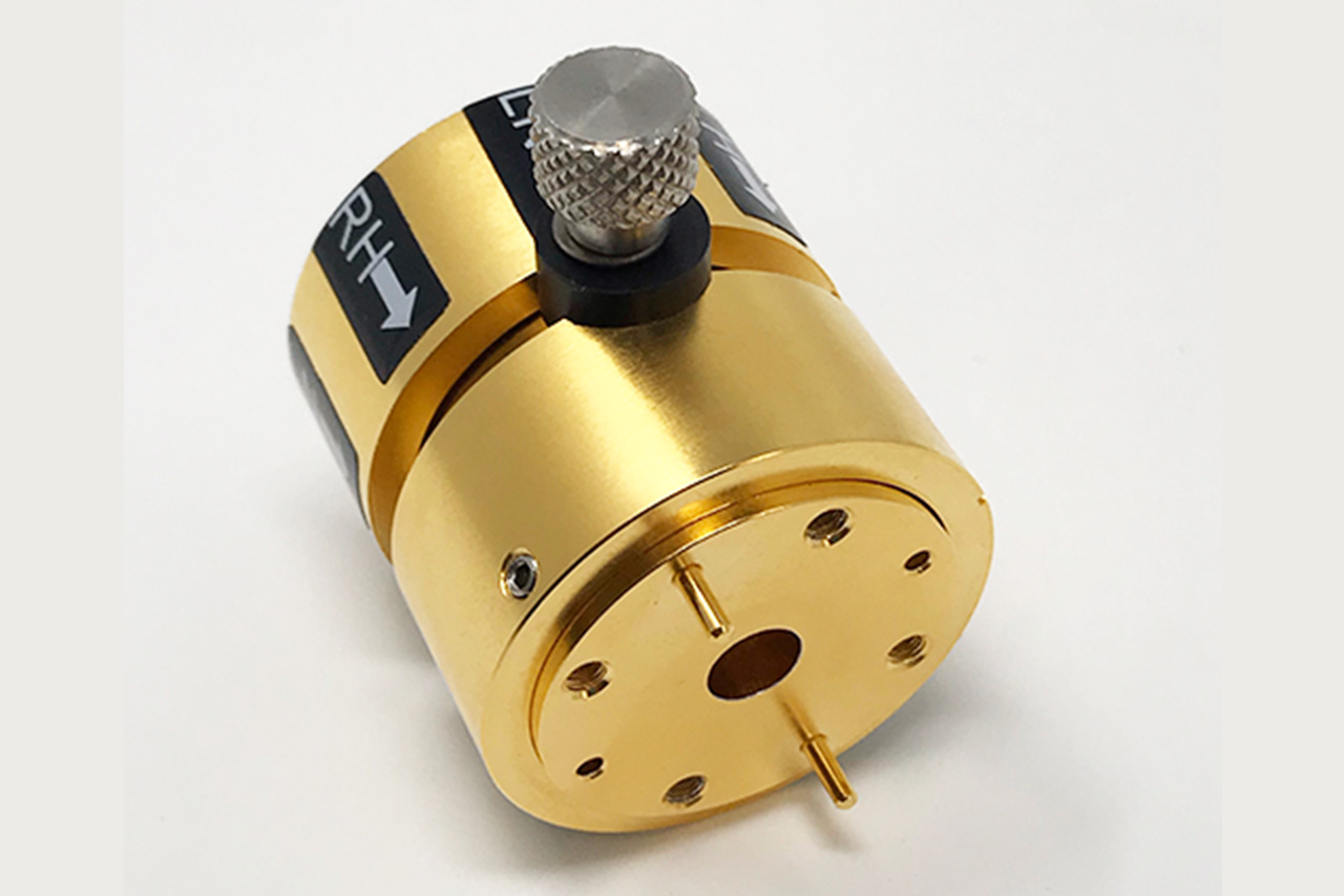
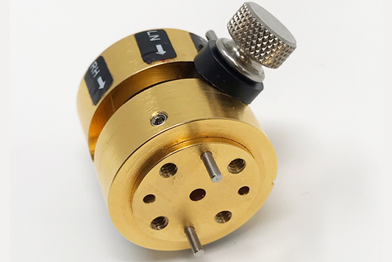
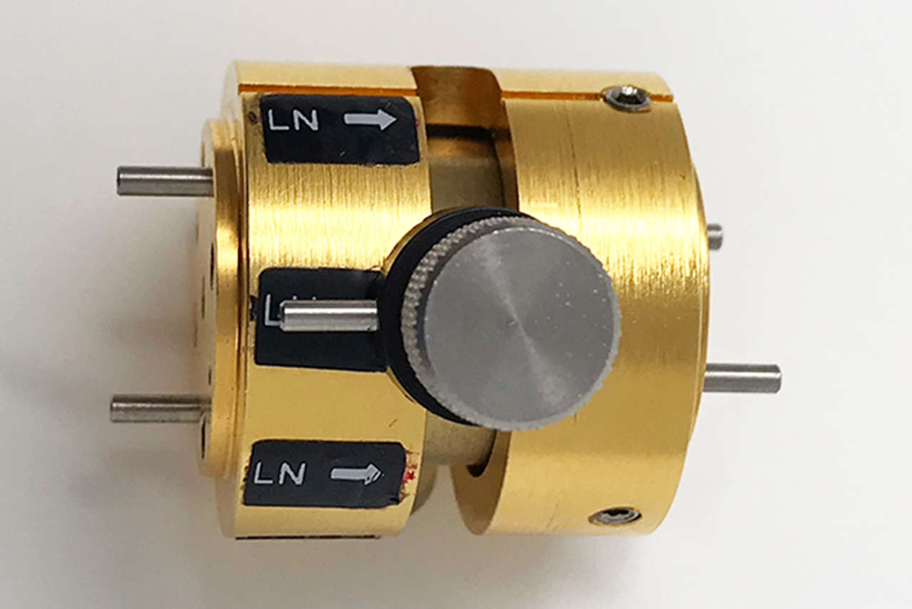
The standard models shown represent only part of Mi-Wave’s broader product capabilities. Custom configurations are available to support specific frequency bands, interfaces, and application requirements, enabling optimized solutions for specialized RF, microwave, and millimeter-wave systems.
Watch our informational video to learn more about this product family, including its key features, operating principles, and common applications.
Explore Mi-Wave’s complete range of dual-polarized antenna solutions engineered for RF, microwave, and millimeter-wave applications. Many configurations are compatible with Mi-Wave Orthomode Transducers (OMTs), supporting Vertical and Horizontal polarization paths, high isolation, and efficient antenna system integration.
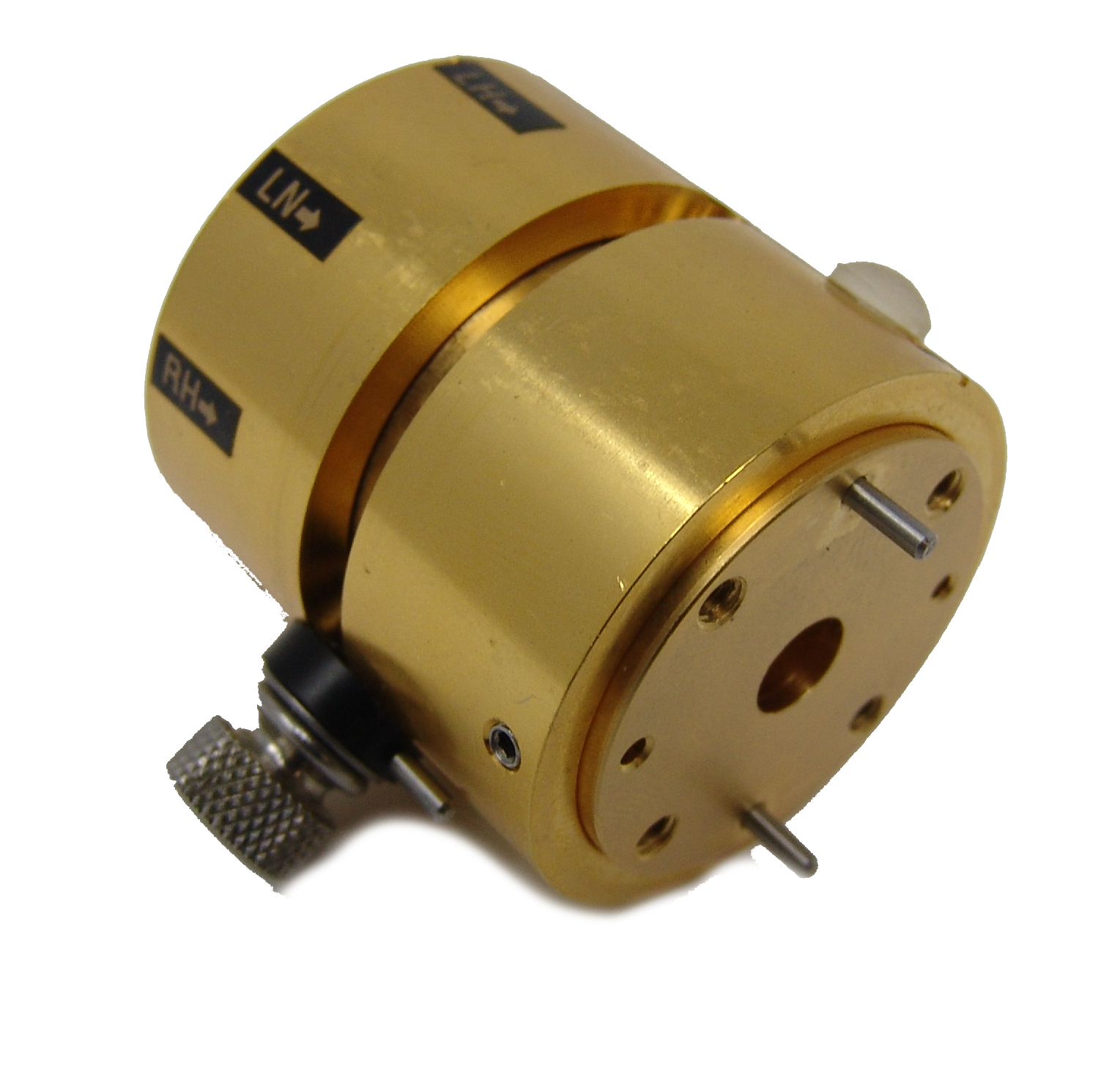
| Model | Band | Circular Waveguide ID (.XXX) / Frequency Range | Insertion Loss Typical | Bandwidth | Axial Ratio | Flange | LINK |
|---|---|---|---|---|---|---|---|
| 282X-XX/.XXX/90 | X-Band | 1.094 = 8–9.97 GHz | .938 = 8.5–11.6 GHz | .797 = 9.7–12.4 GHz | 1 dB | 2 GHz | 1 dB | UG-39/U Flange | |
| 282Ku-XX/.XXX/90 | Ku-Band | .660 = 12.4–14.6 GHz | .550 = 14.6–17.5 GHz | 1 dB | 2.2 GHz | 1 dB | UG-419/U Flange | |
| 282K-XX/.XXX/595 | K-Band | .470 = 17.5–20.5 GHz | .396 = 20.5–24.5 GHz | .328 = 24.5–26.5 GHz | 1 dB | 3 GHz | 1 dB | UG-595/U Flange | |
| 282A-XX/.XXX/599 | Ka-Band | .328 = 26.5–28.5 GHz | .281 = 28.5–33 GHz | .250 = 33–38.5 GHz | .219 = 38.5–40 GHz | 1 dB | 5 GHz | 1 dB | UG-599/U Flange | |
| 282B-XX/.XXX/383 | Q-Band | .250 = 33–38.5 GHz | .219 = 38.5–43 GHz | .188 = 43–50 GHz | 1 dB | 5 GHz | 1 dB | UG-383/U Flange | |
| 282U-XX/.XXX/383 | U-Band | .219 = 40–43 GHz | .188 = 43–50 GHz | .165 = 50–58 GHz | .141 = 58–60 GHz | 1 dB | 6 GHz | 1 dB | UG-383/U-M Flange | |
| 282V-XX/.XXX/385 | V-Band | .165 = 50–58 GHz | .141 = 58–68 GHz | .125 = 68–75 GHz | 1 dB | 7 GHz | 1 dB | UG-385/U Flange | |
| 282E-XX/.XXX/387 | E-Band | .141 = 60–68 GHz | .125 = 68–77 GHz | .110 = 77–87 GHz | .094 = 87–90 GHz | 1 dB | 7 GHz | 1 dB | UG-387/U Flange | |
| 282W-XX/.XXX/387 | W-Band | .125 = 75–77 GHz | .110 = 77–87 GHz | .094 = 87–100 GHz | .082 = 100–110 GHz | 1 dB | 8 GHz | 1 dB | UG-387/U-M Flange | |
| 282F-XX/.XXX/387 | F-Band | .094 = 90–100 GHz | .082 = 100–112 GHz | .075 = 112–125 GHz | .067 = 125–140 GHz | 1 dB | 10 GHz | 1 dB | UG-387/U-M Flange | |
| 282D-XX/.XXX/387 | D-Band | .082 = 110–112 GHz | .075 = 112–125 GHz | .067 = 125–140 GHz | .059 = 140–170 GHz | 1.5 dB | 10 GHz | 1 dB | UG-387/U-M Flange | |
| 282G-XX/.XXX/387 | G-Band | .067 = 125–140 GHz | .059 = 140–220 GHz | 1.7 dB | 10 GHz | 1 dB | UG-387/U-M Flange |
*All data presented is collected from a sample lot.
* Actual data may vary unit to unit, slightly.
*All testing was performed under +25 °C case temperature.
*Consult factory to confirm if material, plating, size, shape, orientation and any electrical parameter is critical for the application as website information is for reference only.
*Millimeter Wave Products, Inc. reserves the right to change the information presented on website without notice as we continue to enhance the performance and design of our products.
Adjustable Circular Polarizer Calculator
Calculate axial ratio, polarization phase error, wavelength, and related parameters for adjustable circular polarization systems.
Axial Ratio Calculator
Calculate polarization axial ratio from the measured major and minor electric-field components.
AR = Major Axis ÷ Minor Axis
AR(dB) = 20 log10(AR)
Quadrature Phase Error
Determine how far the measured phase relationship is from the ideal 90° quadrature condition required for circular polarization.
Frequency & Wavelength
Calculate free-space wavelength from the operating frequency of the polarizer system.
λ = c ÷ f
Polarization Setup Reference
Compare the two orthogonal signal components used to produce circular polarization.
Frequently Asked Questions (FAQ)
What is an adjustable circular polarizer?
An adjustable circular polarizer is an RF component that converts linearly polarized energy into circularly polarized energy by controlling the amplitude and phase relationship between orthogonal electromagnetic field components. The adjustable design provides additional flexibility for optimizing polarization performance.
How is an adjustable circular polarizer different from a fixed polarizer?
A fixed polarizer is designed for a predetermined polarization configuration, while an adjustable polarizer provides greater flexibility for system alignment, testing, and polarization optimization. This makes the Series 283 particularly useful in laboratory, antenna measurement, and configurable RF systems.
What are Series 283 Adjustable Circular Polarizers used for?
They can be used in satellite communications, radar systems, antenna measurement ranges, RF test systems, point-to-point links, telemetry, and research applications where controllable circular polarization is required.
What frequency range does the Series 283 support?
Mi-Wave adjustable circular polarizer solutions are available across microwave and millimeter-wave frequencies from approximately 12 GHz to 220 GHz, depending on the specific configuration.
Can the Series 283 support RHCP and LHCP?
Yes. Adjustable circular polarizers can be configured to support Right-Hand Circular Polarization (RHCP) or Left-Hand Circular Polarization (LHCP) based on the system configuration and polarization requirements.
What is the difference between RHCP and LHCP?
RHCP stands for Right-Hand Circular Polarization, while LHCP stands for Left-Hand Circular Polarization. They describe opposite rotational senses of the electric field as the electromagnetic wave propagates. The applicable handedness convention should always be considered when configuring or measuring a system.
How does an adjustable circular polarizer work?
The polarizer establishes a controlled phase relationship between two orthogonal electromagnetic field components. When the components have approximately equal amplitudes and are in quadrature, the resulting electric field forms circular polarization. Adjustment allows the polarization response to be optimized for the application.
What is axial ratio?
Axial ratio describes the quality of circular polarization by comparing the major and minor axes of the polarization ellipse. An ideal circularly polarized signal has an axial ratio of 1:1, or 0 dB. Lower axial-ratio values generally indicate better circular polarization purity.
Why is a 90-degree phase difference important?
Ideal circular polarization requires two orthogonal field components of equal amplitude with a 90° phase difference. Deviations in amplitude balance or phase can cause the resulting polarization to become elliptical.
Why would I choose an adjustable polarizer?
An adjustable polarizer is useful when engineers need greater control during antenna alignment, system integration, calibration, experimentation, or polarization testing rather than relying solely on a predetermined fixed configuration.
Why use circular polarization?
Circular polarization reduces sensitivity to relative antenna orientation and can help minimize polarization mismatch. It is particularly useful in satellite, radar, telemetry, mobile, and other systems where antenna orientation may vary.
Can Series 283 polarizers be used for antenna testing?
Yes. Adjustable polarizers are particularly useful for RHCP/LHCP testing, axial-ratio measurements, antenna characterization, feed alignment, polarization studies, and RF system calibration.
Are Series 283 polarizers compatible with standard waveguide systems?
Yes. Series 283 polarizers can be configured with standard waveguide interfaces for integration into microwave and millimeter-wave antenna and RF systems.
What parameters are important when selecting an adjustable circular polarizer?
Important considerations include frequency range, bandwidth, axial ratio, insertion loss, VSWR, waveguide size, polarization sense, interface requirements, and adjustment requirements.
Can Mi-Wave provide custom adjustable polarizers?
Yes. Custom configurations can be developed for specific frequency bands, bandwidths, waveguide sizes, flange interfaces, polarization requirements, and mechanical configurations.
Glossary of Adjustable Circular Polarizer Terms
For the Series 283 Adjustable Circular Polarizer page, I would keep most of your terminology but shift the definitions toward adjustability, polarization tuning, and system alignment so it doesn’t duplicate the Series 282 glossary.
Polarization Fundamentals
Adjustable Circular Polarizer
A waveguide RF component that converts linear polarization into circular or elliptical polarization while providing mechanical adjustment to optimize the polarization state for a specific frequency, antenna, or system configuration.
Linear Polarization
A polarization state in which the electric field remains oriented along a fixed plane as the electromagnetic wave propagates.
Circular Polarization
A polarization state in which the electric field rotates continuously as the wave propagates. Ideal circular polarization occurs when two orthogonal field components have equal amplitude and a 90-degree phase difference.
Right-Hand Circular Polarization (RHCP)
One of the two possible rotational senses of a circularly polarized electromagnetic wave.
Left-Hand Circular Polarization (LHCP)
The circular polarization state having the opposite rotational sense from RHCP.
Polarization Sense
The direction of electric-field rotation associated with circular polarization, generally identified as RHCP or LHCP according to the applicable convention and propagation direction.
Polarization Conversion
The process of transforming an electromagnetic signal from one polarization state into another, such as linear-to-circular polarization.
Polarization Adjustment
Mechanical or electrical modification of a polarizer configuration to optimize the desired polarization characteristics.
Polarization Purity
A measure of how closely an RF signal maintains its intended polarization without significant unwanted polarization components.
Cross-Polarization
An unwanted polarization component orthogonal to the desired polarization that can reduce isolation and overall system performance.
Adjustable Polarizer Concepts
Polarizer Adjustment
The process of changing the physical configuration or orientation of an adjustable polarizer to modify its polarization response.
Polarization Optimization
Adjustment of the polarizer to achieve the desired combination of axial ratio, phase relationship, insertion loss, and impedance match.
Orthogonal Field Components
Two perpendicular electric-field components that combine to establish the resulting polarization state.
Amplitude Balance
The relationship between the magnitudes of the two orthogonal field components. Equal amplitudes are required for ideal circular polarization.
Phase Balance
The relationship between the phases of the orthogonal field components. A 90-degree phase difference is required for ideal circular polarization.
90-Degree Phase Difference
The quadrature phase relationship required between equal-amplitude orthogonal field components to produce ideal circular polarization.
Quarter-Wave Relationship
A phase relationship equivalent to 90 electrical degrees and commonly associated with polarization conversion.
Polarization Tuning
Adjustment of the polarizer to obtain the desired polarization response for a particular operating condition.
Polarization Performance
Axial Ratio
The ratio between the major and minor axes of the polarization ellipse. It is one of the primary measurements used to evaluate circular polarization quality.
Axial Ratio (dB)
Axial ratio expressed logarithmically in decibels. An ideal circularly polarized signal has an axial ratio of 0 dB, with increasing values indicating progressively more elliptical polarization.
Polarization Ellipse
A representation of the path traced by the electric-field vector as an electromagnetic wave propagates.
Elliptical Polarization
A polarization state in which the electric-field vector traces an ellipse. It generally results when orthogonal components have unequal amplitudes and/or a phase relationship other than the ideal quadrature condition.
Polarization Mismatch
A difference between the polarization states of transmitting and receiving systems that can reduce transferred signal power.
Polarization Mismatch Loss
Signal loss resulting from differences between the polarization states of transmitting and receiving antennas.
Polarization Isolation
The degree of separation between different polarization states or channels within an RF system.
Orientation Tolerance
The ability of a circularly polarized system to maintain signal transfer despite relative rotational differences between transmitting and receiving antennas.
Electrical Performance Terms
Insertion Loss
The reduction in RF signal power resulting from the addition of the polarizer to the transmission path.
VSWR (Voltage Standing Wave Ratio)
A measurement of impedance matching. Lower VSWR generally indicates lower reflected power and better RF power transfer.
Return Loss
A logarithmic measurement describing how much RF power is reflected because of impedance mismatch.
Reflection Coefficient
The ratio between reflected and incident RF wave amplitudes at an impedance discontinuity.
Bandwidth
The frequency range over which the polarizer maintains its specified RF and polarization performance.
Phase Stability
The ability of the polarizer to maintain the intended phase relationship between orthogonal field components across its operating conditions.
Amplitude Stability
The consistency of the relative amplitudes of orthogonal field components across the operating range.
RF & Frequency Terms
Radio Frequency (RF)
Electromagnetic frequencies used for communications, radar, sensing, testing, and other wireless applications.
Microwave
The portion of the RF spectrum generally associated with frequencies from approximately 1 GHz to 30 GHz.
Millimeter-Wave (mmWave)
Frequencies generally spanning approximately 30 GHz to 300 GHz, corresponding to wavelengths on the millimeter scale.
Operating Frequency
The frequency at which the polarizer and associated RF system are being operated.
Operating Frequency Range
The span of frequencies over which a polarizer is designed to maintain acceptable performance.
Frequency Band
A defined portion of the RF spectrum associated with particular applications or standardized waveguide sizes.
Wavelength (λ)
The physical distance traveled during one complete cycle of an electromagnetic wave.
Electrical Length
The effective length of an RF structure expressed relative to the wavelength or phase progression of the signal.
Waveguide Terms
Waveguide
A metallic transmission structure used to guide electromagnetic energy at microwave and millimeter-wave frequencies.
Waveguide Polarizer
A polarization-conversion device incorporated into a waveguide transmission path.
Waveguide Interface
The mechanical and electrical connection between the polarizer and other waveguide components.
Waveguide Size
The standardized physical dimensions of a waveguide associated with a particular operating frequency range.
Flange Interface
The mechanical mating surface used to connect waveguide components.
Waveguide Mode
The electromagnetic field configuration that propagates through a waveguide.
Cutoff Frequency
The minimum frequency at which a particular waveguide mode can propagate.
Mode Conversion
The transformation of electromagnetic energy from one waveguide propagation mode into another.
Antenna & System Integration
Antenna Feed System
The collection of RF components responsible for transferring energy between a transmission line or waveguide and an antenna aperture.
Feed Horn
A horn antenna used to illuminate a reflector or serve as part of an antenna feed assembly.
Reflector Antenna
An antenna using a reflective surface to focus RF energy between a feed and a directional beam.
Orthomode Transducer (OMT)
A waveguide component used to separate or combine two orthogonal linear polarization channels.
System Alignment
The process of mechanically and electrically positioning RF components to achieve the intended antenna, polarization, and signal performance.
Boresight
The primary pointing direction or reference axis of a directional antenna.
Antenna Polarization
The polarization state associated with the electromagnetic field transmitted or received by an antenna.
Measurement & Adjustment Terms
Polarization Measurement
The process of characterizing the polarization properties of an antenna or RF signal.
Axial Ratio Measurement
A measurement used to determine how closely a signal approaches ideal circular polarization.
Polarization Calibration
The process of establishing or verifying a known polarization condition within an RF measurement system.
Antenna Characterization
Measurement of antenna properties such as gain, radiation pattern, beamwidth, polarization, axial ratio, and impedance match.
RF Test System
A laboratory or production setup used to measure and validate RF components, antennas, and subsystems.
Repeatability
The ability to obtain consistent results when the same adjustment or measurement procedure is repeated.
Common Applications
Satellite Communications (SatCom)
Satellite-based RF communication systems where circular polarization is frequently used for uplink, downlink, telemetry, and tracking applications.
Radar Systems
RF sensing systems that can use controlled polarization for target detection, characterization, calibration, and research.
Antenna Measurement Range
A controlled test environment used to characterize antenna radiation patterns, gain, polarization, and other performance parameters.
RF & Millimeter-Wave Research
Experimental work involving high-frequency communication, sensing, propagation, antennas, and component development.
Point-to-Point RF Link
A directional wireless connection between two locations where polarization compatibility contributes to reliable signal transfer.
Custom RF System
An application-specific microwave or millimeter-wave assembly designed around particular frequency, polarization, mechanical, or performance requirements.
This version makes the glossary much more specifically relevant to the Series 283 Adjustable Circular Polarizers, while terms such as Axial Ratio, Polarization Adjustment, Polarization Tuning, Phase Balance, Amplitude Balance, RHCP/LHCP, and System Alignment give the page useful long-tail SEO coverage without simply repeating the Series 282 content.
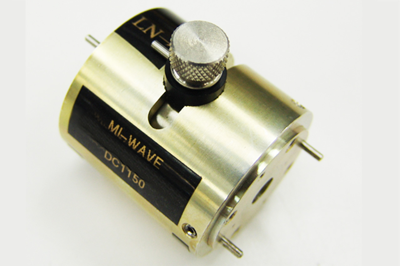
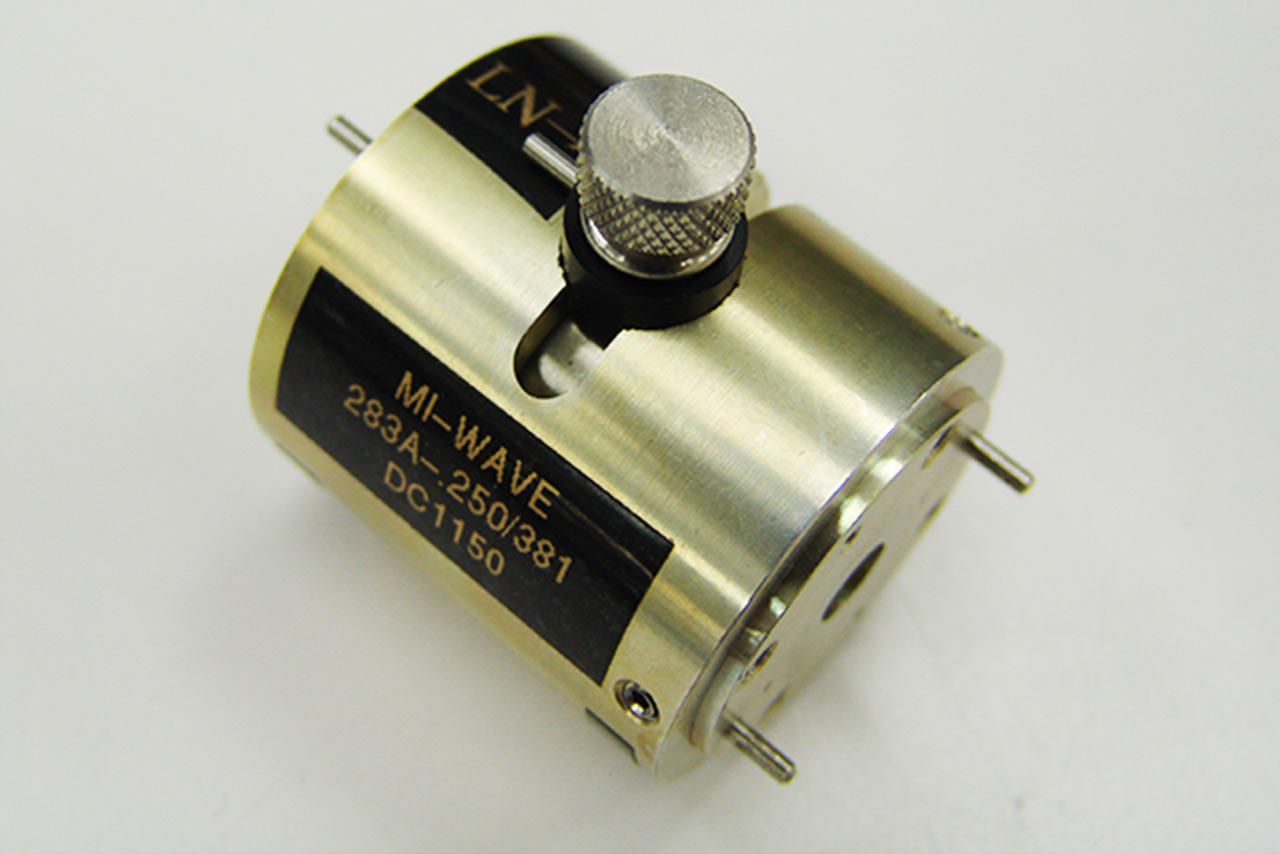
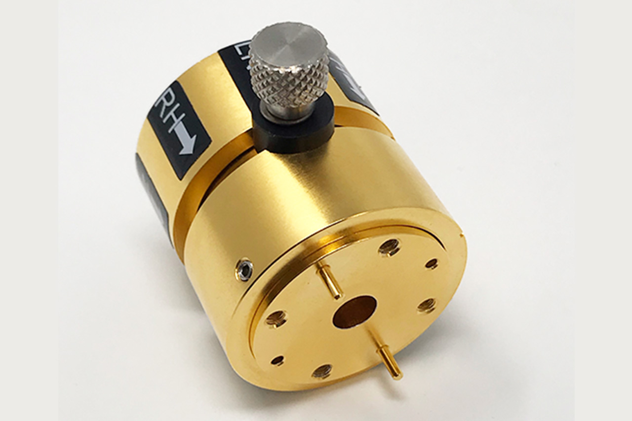
Interested in this product or other Mi-Wave solutions?
Contact our team to discuss your frequency range, interface needs, and application requirements.
Custom configurations are available for specialized RF, microwave, and millimeter-wave systems.
Return to Polarizers
Return to Products Page
