

Description:
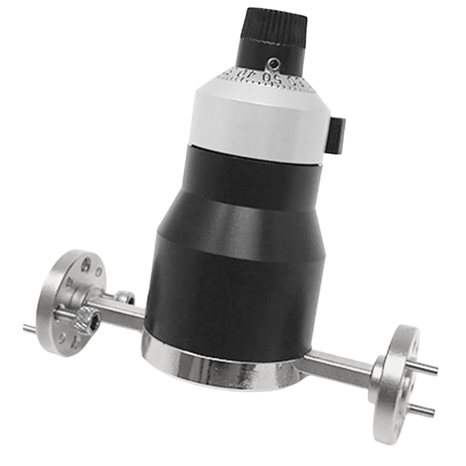
Mi-Wave’s 520 Series Uncalibrated Variable Attenuators and 522 Calibrated Attenuators are available in standard waveguide sizes from 8 to 220 GHz. The attenuating element in each unit provides a variable attenuation, from 0 dB to 25 dB minimum. Precision-designed internal controls are accurately contoured to provide a low bilateral VSWR and minimum variation of attenuation with frequency.
Features
• Dial Driven
• Low Cost
• Compact, Mechanically Stable Design
• Wide Range of Attenuation Values
• Smooth, Spring-loaded Setting Control
Applications
• Instrumentation
• Manual Test Setups
The standard models shown represent only part of Mi-Wave’s broader product capabilities. Custom configurations are available to support specific frequency bands, interfaces, and application requirements, enabling optimized solutions for specialized RF, microwave, and millimeter-wave systems.
*Actual product may be different from the image shown per customers specifcations
*All data presented is collected from a sample lot.
* Actual data may vary unit to unit, slightly.
*All testing was performed under +25 °C case temperature.
*Consult factory to confirm if material, plating, size, shape, orientation and any electrical parameter is critical for the application as website information is for reference only.
*Millimeter Wave Products, Inc. reserves the right to change the information presented on website without notice as we continue to enhance the performance and design of our products.
Features & Specifications
Mi-Wave’s 520 and 522 Series waveguide attenuators are engineered to provide stable, manually adjustable attenuation for microwave and millimeter-wave systems from 8 GHz to 220 GHz.
Frequency Coverage: 8 GHz to 220 GHz
Available in standard waveguide sizes across a broad microwave and millimeter-wave frequency range, supporting laboratory, instrumentation, and test applications.
520 Series Uncalibrated and 522 Series Calibrated Options
The 520 Series is designed for variable attenuation where calibrated readout is not required, while the 522 Series provides calibrated attenuation for more repeatable level setting applications.
Variable Attenuation: 0 dB to 25 dB Minimum
Each unit provides adjustable attenuation from 0 dB to at least 25 dB, supporting signal level setting, isolation, and measurement preparation.
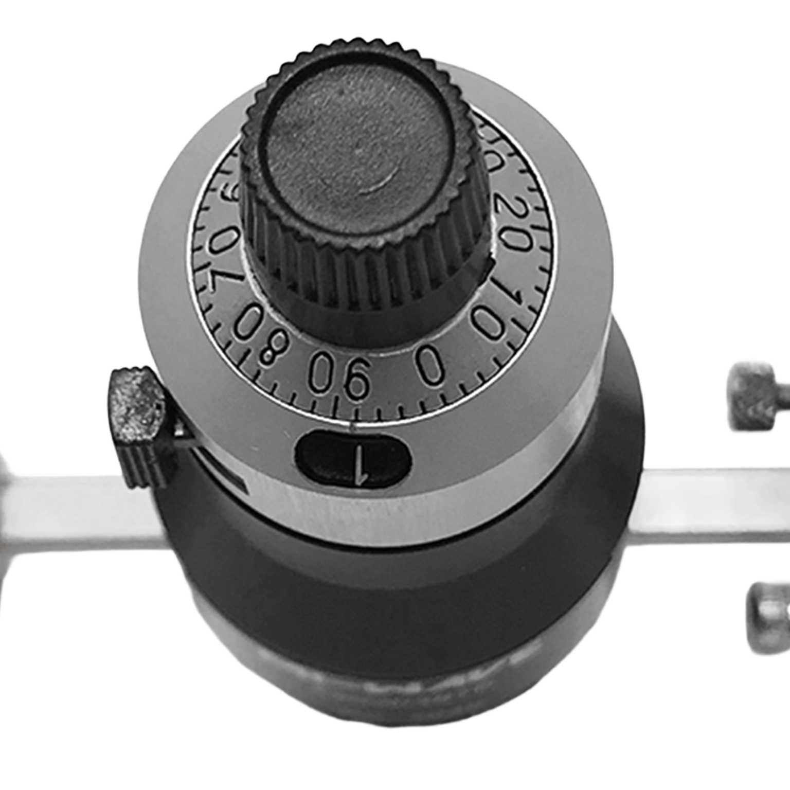
Dial-Driven Manual Control
A dial-operated adjustment mechanism allows users to vary attenuation manually with simple, direct operation.
Low Bilateral VSWR
Precision-designed internal contours help minimize reflections in either direction of signal travel, supporting better impedance matching and more reliable measurements.
Minimal Attenuation Variation with Frequency
Engineered to maintain stable attenuation behavior across the operating band, reducing performance inconsistency as frequency changes.
Compact, Mechanically Stable Design
Designed for dependable physical stability in laboratory and bench environments where reliable settings are required over repeated use.
Smooth, Spring-Loaded Setting Control
The spring-loaded mechanism provides controlled, stable adjustment and helps maintain constant attenuation under normal vibration and orientation changes.
Wide Range of Attenuation Values
Supports a useful range of manual attenuation settings for instrumentation, test setups, and isolation applications.
Low-Cost Solution
Provides practical manual waveguide attenuation at a lower cost than more complex programmable or precision electronic alternatives.
Applications
Mi-Wave’s 520 and 522 Series Variable Waveguide Attenuators are used in microwave and millimeter-wave systems where reliable manual attenuation control is needed from 8 GHz to 220 GHz.
Instrumentation
Used in RF and microwave instrumentation setups to establish and adjust signal levels during testing, evaluation, and measurement.
Manual Test Setups
Ideal for bench testing and manually configured measurement systems where engineers need direct attenuation control without automated interfaces.
Initial Power Level Setting
Useful for establishing starting signal levels in RF chains before additional calibration, measurement, or component evaluation.
Substitution-Method Attenuation Measurements
Provides dependable manual attenuation for substitution-based measurement methods that require stable and repeatable initial level setting.
Isolating Pad Applications
Can be used as an isolating pad in microwave systems to reduce signal levels and help improve system stability during testing.
Laboratory RF Development
Supports engineering development and troubleshooting workflows where simple, reliable attenuation adjustment is needed.
Microwave and Millimeter-Wave Measurements
Suitable for controlled attenuation tasks across standard waveguide bands used in high-frequency test environments.
Frequently Asked Questions (FAQ)
What is the difference between the 520 Series and 522 Series attenuators?
The 520 Series provides uncalibrated variable attenuation, while the 522 Series provides calibrated attenuation for applications that require more defined and repeatable level setting.
What frequency range do the 520 and 522 Series cover?
These attenuators are available in standard waveguide sizes covering approximately 8 GHz to 220 GHz.
What attenuation range is available?
Each unit provides variable attenuation from 0 dB to 25 dB minimum, depending on model and waveguide size.
Are these attenuators manually adjusted?
Yes. Both series use a dial-driven manual control for direct attenuation adjustment.
What does low bilateral VSWR mean?
Low bilateral VSWR means the attenuator is designed to maintain good impedance matching in either direction of signal travel, helping reduce reflections and improve measurement accuracy.
What types of applications are these attenuators used for?
They are commonly used in instrumentation, manual test setups, isolating pad applications, and substitution-method attenuation measurements.
Are these attenuators suitable for stable lab measurements?
Yes. Their mechanically stable design and spring-loaded setting control help maintain constant attenuation under normal vibration and orientation conditions.
Why would I choose an uncalibrated attenuator instead of a calibrated one?
An uncalibrated attenuator can be a cost-effective choice when relative attenuation adjustment is sufficient and precise calibrated readout is not required.
RF Attenuator Calculators
These RF attenuator calculators are designed to support microwave and millimeter-wave engineers working with direct reading precision attenuators, waveguide attenuators, and laboratory RF test setups. Use these tools to quickly convert attenuation values, estimate power levels, evaluate cascaded loss, and analyze impedance match performance for systems spanning X-Band through J-Band.
dB to Power Ratio
Convert attenuation or gain in decibels to a linear power ratio.
Power Ratio to dB
Convert a linear power ratio into decibels.
dBm to Watts
Convert RF power in dBm to watts for test and system-level calculations.
Watts to dBm
Convert watts to dBm for RF signal level analysis.
Cascaded Attenuation Calculator
Add multiple attenuator values together to determine total path attenuation.
VSWR to Return Loss
Estimate return loss from a known VSWR value.
Glossary of Dial-Type Waveguide Attenuator Terms
Attenuator Fundamentals
Variable Attenuator
An attenuator that allows the user to adjust the amount of signal reduction over a defined range.
Uncalibrated Attenuator
An attenuator with adjustable signal reduction but without a calibrated scale intended for exact attenuation readout.
Calibrated Attenuator
An attenuator with a defined scale or reference that allows more repeatable and known attenuation settings.
Waveguide Attenuator
An attenuator designed for use in rectangular waveguide systems at microwave and millimeter-wave frequencies.
Dial-Type Attenuator
An attenuator that is adjusted using a manual dial mechanism.
Electrical Performance
Attenuation (dB)
The reduction of RF signal power expressed in decibels.
Attenuation Range
The span of attenuation values available from the device, such as 0 dB to 25 dB minimum.
Low Bilateral VSWR
A design characteristic indicating low reflected power and good impedance matching in both directions through the attenuator.
VSWR (Voltage Standing Wave Ratio)
A measure of impedance matching between RF components.
Insertion Loss
The signal loss introduced by inserting a component into an RF path, beyond the intended attenuation function.
Frequency Response
How consistently the attenuator performs as frequency changes across its operating band.
RF and Frequency
Radio Frequency (RF)
Electromagnetic signals used in communications, sensing, and electronic measurement.
Microwave Frequencies
Frequencies generally spanning 1 GHz to 30 GHz.
Millimeter-Wave (mmWave)
Frequencies from 30 GHz to 300 GHz used in advanced communications, radar, and test systems.
Waveguide Size
The physical size of the waveguide interface, which determines the operating frequency band.
Frequency Range
The range of frequencies over which the attenuator is designed to operate effectively.
Mechanical and Design
Mechanically Stable Design
A design intended to resist unintended setting changes due to movement, vibration, or handling.
Spring-Loaded Setting Control
A control mechanism that uses spring tension to provide smoother adjustment and stable position holding.
Internal Contouring
Precision shaping of internal attenuator features to optimize RF performance, minimize reflections, and reduce variation with frequency.
Stable Setting Control
A control mechanism designed to hold attenuation settings consistently under normal operating conditions.
Measurement and Applications
Instrumentation
RF and microwave test equipment used to evaluate signals, components, and systems.
Manual Test Setup
A non-automated test arrangement where settings are adjusted directly by the user.
Substitution-Method Attenuation Measurement
A measurement approach where attenuation is determined by replacing one signal path or setting with another while maintaining equivalent response.
Initial Power Level Setting
The process of establishing a starting signal level for testing, calibration, or system adjustment.
Isolating Pad
A device or attenuation function used to reduce signal interaction between components and improve measurement stability.
Reliable Level Setting
The ability to set and maintain a desired attenuation level consistently during testing or operation.
Note: Our website contains just a few types of Attenuators we build. Consult with us for your specific needs.
| Model | Minimum Frequency (GHz) | Maximum Frequency (GHz) | Insertion Loss at 0 (dB) setting | Attenuation Range (dB) | Power Handling (Watts) | RF Ports | LINK |
|---|---|---|---|---|---|---|---|
| 520K/595 | 18 | 26.5 | 0.3 | 0-30 | 10 | WR-42 Waveguide, UG-595/U Flange | |
| 520(34)/595 | 22 | 33 | 0.3 | 0-25 | 10 | WR-34 Waveguide, UG-595/U Flanges | |
| 520A/599 | 26.5 | 40 | 0.3 | 0-25 | 10 | WR-28 Waveguide, UG-599 | |
| 520B/383 | 33 | 50 | 0.3 | 25 | 7 | WR-19 Waveguide, UG-383/U-M Flange | |
| 520U/383 | 40 | 60 | 0.3 | 0-25 | 5 | WR-19 Waveguide, UG-383/U-M Flange | |
| 520V/385 | 50 | 75 | 0.4 | 0-25 | 5 | WR-15 Waveguide, UG-385/U Flange | |
| 520E/387 | 60 | 90 | 0.4 | 0-25 | 2 | WR-12 Waveguide, UG-387/U Flange | |
| 520W/387 | 75 | 110 | 0.4 | 0-25 | 2 | WR-10 Waveguide, UG-387/U-M Flange | |
| 520F/387 | 90 | 140 | 0.5 | 0-25 | 0.1 | WR-08 Waveguide, UG-387/U-M Flange | |
| 520D/387 | 110 | 170 | 0.7 | 0-20 | 0.1 | WR-06 Waveguide UG-387/U-M Flange | |
| 520G/387 | 140 | 220 | 1.0 | 0-25 | 0.1 | WR-08 Waveguide, UG-387/U-M Flange |
Calibrated & Uncalibrated Waveguide Attenuators
The 520/522 Series Variable Attenuators are useful in applications that require a reliable level setting or isolating pad. They provide maximum accuracy in establishing initial power levels in substitution-method attenuation measurements. Designed to maintain reliable performance for accurate test measurements, the stable setting control of these devices maintains constant attenuation under all normal conditions of vibration and orientation.
Other Bands Available
• WR-90
• WR-75
• WR-62
• WR-34