

Description:
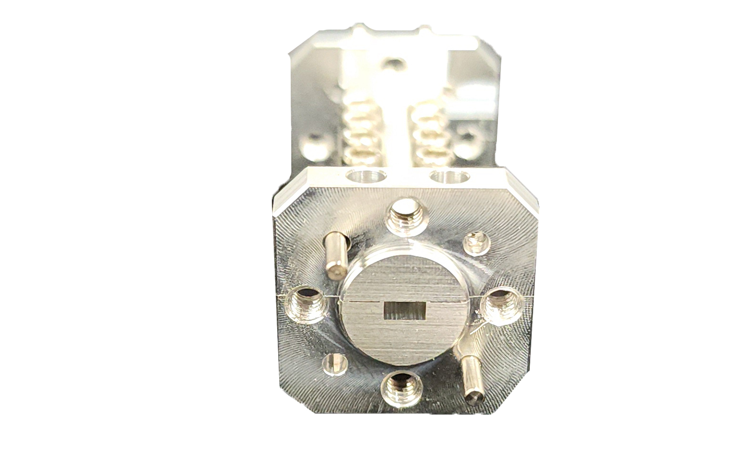
Mi-Wave’s 460 Series Bandpass Filters are used for narrow and wideband applications. Pass bands are typically from 1% to 10%. This design is well suited for frequency diplexers used in communication systems or any application where narrow bandwidths are required. Insertion losses are typically in the 0.8 dB to 2.0 dB area depending upon rejection levels. The 460 Series Bandpass filter can be designed from 8 to 140GHz. Please consult Mi-Wave for further dimensions and specific technical data.
The standard models shown represent only part of Mi-Wave’s broader product capabilities. Custom configurations are available to support specific frequency bands, interfaces, and application requirements, enabling optimized solutions for specialized RF, microwave, and millimeter-wave systems.
*Actual product may be different from the image shown per customers specifcations
*All data presented is collected from a sample lot.
* Actual data may vary unit to unit, slightly.
*All testing was performed under +25 °C case temperature.
*Consult factory to confirm if material, plating, size, shape, orientation and any electrical parameter is critical for the application as website information is for reference only.
*Millimeter Wave Products, Inc. reserves the right to change the information presented on website without notice as we continue to enhance the performance and design of our products.
| Min Passband Frequency (GHz) | Max Passband Frequency (GHz) | Min Rejection Frequency Low (GHz) | Max Rejection Frequency Low (GHz) | Min Rejection Frequency High (GHz) | Max Rejection Frequency High (GHz) | Rejection (dB) | Waveguide Port |
|---|---|---|---|---|---|---|---|
| 22 | 32 | DC | 18 | 37 | 75 | 40 | WR-28 |
| 22 | 35 | DC | 20 | 40 | 72 | 40 | WR-28 |
| 22 | 38 | DC | 19.6 | 41 | 45 | 50 | WR-28 |
| 22 | 42 | DC | 20 | 48 | 95 | 60 | WR-28 |
| 27.5 | 32.5 | DC | 23.5 | 36.5 | 41.5 | 40 | WR-28 |
| 29 | 35 | DC | 27 | 37 | 45 | 40 | WR-28 |
| 30 | 45 | DC | 28 | 47 | 90 | 40 | WR-22 |
| 30 | 50 | DC | 25 | 56 | 100 | 40 | WR-22 |
| 32 | 38 | DC | 28 | 40 | 46 | 40 | WR-28 |
| 33 | 37 | DC | 31 | 39 | 46 | 40 | WR-28 |
| 33 | 50 | DC | 25 | 56 | 60 | 40 | WR-22 |
| 34 | 67 | DC | 30 | 69 | 120 | 40 | WR-19 |
| 35.26 | 36.26 | DC | 33.9 | 38 | 45 | 40 | WR-28 |
| 36 | 60 | DC | 29 | 66 | 120 | 40 | WR-19 |
| 40 | 50 | DC | 34 | 57 | 65 | 60 | WR-22 |
| 43 | 46 | DC | 42 | 47 | 55 | 30 | WR-22 |
| 47 | 57 | DC | 44 | 62 | 85 | 40 | WR-15 |
| 47 | 59 | DC | 44 | 63 | 78 | 50 | WR-15 |
| 49.75 | 50.25 | DC | 49 | 51 | 60 | 30 | WR-15 |
| 50 | 75 | DC | 44 | 80 | 110 | 40 | WR-15 |
| 51 | 55 | DC | 45 | 61 | 80 | 40 | WR-15 |
| 51.5 | 54.5 | DC | 44 | 62 | 70 | 40 | WR-15 |
| 53.5 | 54.5 | DC | 52 | 55 | 65 | 40 | WR-15 |
| 54.5 | 56.5 | DC | 53 | 57 | 70 | 50 | WR-15 |
| 55.75 | 56.25 | DC | 54.75 | 57.5 | 70 | 40 | WR-15 |
| 70 | 90 | DC | 60 | 93.3 | 130 | 40 | WR-12 |
| 71 | 76 | DC | 67 | 81 | 105 | 50 | WR-10 |
| 71 | 76 | DC | 67 | 81 | 105 | 50 | WR-12 |
| 73 | 76 | DC | 67 | 82 | 100 | 40 | WR-12 |
| 74 | 76 | DC | 70 | 80 | 100 | 40 | WR-12 |
| 75 | 78 | DC | 71 | 82 | 100 | 50 | WR-12 |
| 76 | 77 | DC | 74.5 | 78.5 | 90 | 50 | WR-10 |
| 76 | 81 | DC | 73 | 84 | 105 | 40 | WR-12 |
| 81 | 86 | DC | 78 | 88 | 120 | 50 | WR-10 |
| 81 | 86 | DC | 78 | 90 | 120 | 50 | WR-12 |
| 81 | 87 | DC | 78 | 90 | 120 | 30 | WR-12 |
| 82.5 | 85.5 | DC | 79 | 93.5 | 110 | 40 | WR-10 |
| 82.5 | 87 | DC | 80 | 90 | 120 | 40 | WR-12 |
| 90 | 98 | DC | 88 | 102 | 110 | 25 | WR-10 |
| 92 | 96 | DC | 90 | 98 | 130 | 40 | WR-10 |
| 92 | 100 | DC | 88 | 104 | 110 | 50 | WR-10 |
| 92.5 | 95.5 | DC | 91.5 | 97 | 97.5 | 20 | WR-10 |
| 93.2 | 95.2 | DC | 91 | 98.5 | 105 | 40 | WR-10 |
| 98 | 102 | DC | 95 | 105 | 110 | 40 | WR-10 |
Key Performance Features
460 Series Bandpass Filters are designed and manufactured to deliver consistent performance across a wide range of operating environments.
-
Frequency coverage from approximately 8 GHz to 140 GHz
-
Narrowband and wideband configurations with typical bandwidths from 1 percent to 10 percent of center frequency
-
Low insertion loss to preserve signal strength and system sensitivity
-
Low VSWR for improved impedance matching and reduced signal reflections
-
High out-of-band rejection to suppress harmonics, spurious signals, and adjacent channel interference
-
Waveguide interfaces matched to standard WR sizes across supported frequency bands
-
Precision-machined metal housings for mechanical stability and thermal consistency
-
Repeatable RF performance suitable for both lab and field applications
Applications for 460 Series Bandpass Filters
The MIWV 460 Series Bandpass Filters are designed for integration into a wide range of RF, microwave, and millimeter-wave systems where precise frequency selection, interference suppression, and signal integrity are essential. These filters are commonly used in both commercial and defense-grade platforms, supporting fixed, mobile, airborne, and space-constrained applications.
Satellite Communications (SatCom)
460 Series bandpass filters are widely used in satellite communication systems to isolate uplink and downlink frequency bands, suppress out-of-band interference, and protect sensitive receiver components.
Typical SatCom applications include:
-
Ground-based satellite terminals and gateway stations
-
Airborne and maritime SatCom platforms
-
Ka-band and Q-band satellite uplinks and downlinks
-
Payload frequency management and channel isolation
-
Interference mitigation in crowded satellite frequency allocations
-
Protection of LNAs, BUCs, and frequency converters
These filters help improve link stability, reduce noise, and maintain regulatory compliance in high-density satellite environments.
Radar Systems
In radar applications, 460 Series bandpass filters are used to improve target detection, reduce clutter, and protect receiver front ends from unwanted signals.
Common radar uses include:
-
Fire-control and target-tracking radar
-
Surveillance and perimeter monitoring radar
-
Imaging and high-resolution radar systems
-
Ground-based, airborne, and maritime radar platforms
-
Harmonic suppression in high-power radar transmit chains
-
Receiver protection from strong out-of-band signals
By tightly controlling the radar operating band, these filters enhance signal-to-noise ratio and overall system performance.
Electronic Warfare and Signal Intelligence (EW / SIGINT)
Electronic warfare and SIGINT systems require high selectivity and strong out-of-band rejection, making the 460 Series well suited for these mission-critical applications.
Use cases include:
-
Threat signal isolation and monitoring
-
Interference and jamming mitigation
-
Spectrum surveillance and signal collection
-
Front-end filtering for wideband receivers
-
Channelized receivers and frequency-selective architectures
-
Protection of sensitive EW receiver chains
The robust mechanical construction and repeatable RF performance make these filters suitable for deployed EW systems.
RF Upconversion and Downconversion Chains
460 Series Bandpass Filters are commonly integrated into frequency conversion architectures to remove unwanted mixer products and spurious signals.
Applications include:
-
RF upconverters and downconverters
-
Block upconverters (BUCs) and low-noise block downconverters (LNBs)
-
Intermediate frequency (IF) and RF stage filtering
-
Harmonic and image rejection after mixing stages
-
Clean signal generation for transmit chains
These filters help maintain spectral purity and prevent interference between system stages.
Test and Measurement Systems
In laboratory and production environments, 460 Series bandpass filters are used to ensure accurate, repeatable measurements at high frequencies.
Typical test applications include:
-
Millimeter-wave test benches and calibration setups
-
Signal generators and spectrum analyzers
-
Automated test equipment (ATE)
-
Device characterization and validation
-
Noise figure and linearity measurements
-
Production testing of RF and mmWave components
Their stable performance makes them ideal for R&D and manufacturing environments.
High-Data-Rate Wireless and Point-to-Point Links
460 Series bandpass filters support high-frequency wireless communication systems where spectral efficiency and interference control are critical.
Applications include:
-
Point-to-point microwave and millimeter-wave backhaul
-
Fixed wireless access (FWA) systems
-
High-capacity data links
-
Short-range high-bandwidth communication systems
-
Experimental and emerging wireless technologies
These filters help maintain link reliability in dense RF environments.
Scientific, Aerospace, and Research Applications
460 Series filters are also used in scientific instrumentation and advanced research platforms that operate at microwave and millimeter-wave frequencies.
Examples include:
-
Radio astronomy and remote sensing systems
-
Atmospheric and environmental monitoring instruments
-
University and government research laboratories
-
Spaceborne and airborne experimental payloads
-
Advanced sensing and imaging platforms
System Protection and Interference Mitigation
Across all industries, 460 Series Bandpass Filters are used to:
-
Protect sensitive RF receivers from overload
-
Suppress out-of-band noise and interference
-
Improve system dynamic range
-
Maintain compliance with spectral regulations
-
Enhance overall RF system reliability
Glossary of RF Bandpass Filter Terms
Core Frequency Definitions
Passband
The frequency range transmitted through the bandpass filter with minimal attenuation. Signals within the passband experience low insertion loss and are preserved for further processing in the RF signal chain.
Stopband
Frequency ranges outside the passband that are strongly attenuated by the filter. Stopbands are designed to suppress unwanted signals, noise, harmonics, and interference.
Cutoff Frequency
The frequency at which signal attenuation reaches a specified reference level relative to the passband, most commonly 3 dB. The lower cutoff frequency (f1) and upper cutoff frequency (f2) define the edges of the passband.
Center Frequency (fc)
The midpoint of the passband, calculated from the lower and upper cutoff frequencies. Center frequency is used as a reference for defining filter performance, bandwidth, and fractional bandwidth.
Bandwidth and Selectivity
Bandwidth (BW)
The width of the passband, defined as the difference between the upper and lower cutoff frequencies (f2 − f1). Bandwidth directly impacts channel selectivity and interference rejection.
Fractional Bandwidth (FBW)
Bandwidth normalized to center frequency (BW/fc). Fractional bandwidth is commonly expressed as a percentage and is widely used in RF specifications, datasheets, and RFQs to compare filters operating at different frequency ranges.
Q Factor
A measure of filter selectivity related to the ratio of center frequency to bandwidth (fc/BW). Higher Q indicates a narrower passband and greater selectivity.
Loss and Matching Parameters
Insertion Loss (S21)
The amount of signal power lost through the filter within the passband, typically measured in decibels. Low insertion loss is critical for maintaining system noise figure, signal strength, and link margin.
Return Loss (S11)
A measure of reflected RF power caused by impedance mismatch at the filter input or output. Higher return loss values indicate better impedance matching and lower reflections.
VSWR (Voltage Standing Wave Ratio)
A ratio derived from the reflection coefficient that indicates impedance matching quality. Lower VSWR values correspond to improved power transfer and reduced stress on RF components such as amplifiers and mixers.
Rejection and Interference Control
Out-of-Band Rejection
The attenuation provided outside the passband to suppress unwanted signals, harmonics, spurious emissions, image frequencies, and adjacent-channel interference. High out-of-band rejection is critical in dense RF environments.
Skirt Selectivity
The steepness of attenuation at the edges of the passband. Steeper skirts indicate higher selectivity and improved separation between desired and undesired signals.
Filter Structures and Implementations
Waveguide Bandpass Filter
A bandpass filter implemented using waveguide resonant structures to achieve low insertion loss, high power handling, and stable performance at microwave and millimeter-wave frequencies. Commonly used in SatCom, radar, and aerospace systems.
Cavity Filter
A type of bandpass filter that uses metallic resonant cavities to define the passband and rejection characteristics, offering excellent selectivity and power handling.
Resonator
A structure within a filter that stores electromagnetic energy at a specific frequency. Multiple resonators are coupled together to form a bandpass filter response.
Measurement and Performance Metrics
S-Parameters
Scattering parameters used to characterize RF components. For bandpass filters, S11 represents input reflection (return loss) and S21 represents forward transmission (insertion loss).
Insertion Loss Flatness
The variation of insertion loss across the passband. Low ripple or flat insertion loss is important for maintaining consistent signal amplitude.
Group Delay
The frequency-dependent time delay introduced by the filter. Excessive group delay variation can distort wideband or digitally modulated signals.
Application and System-Level Terms
Receiver Front-End Protection
The use of bandpass filters to prevent strong out-of-band signals from overloading low-noise amplifiers and mixers.
Image Frequency Rejection
Suppression of unwanted image frequencies generated in frequency conversion stages.
Harmonic Suppression
Reduction of harmonic signals produced by nonlinear RF components.
Spectral Compliance
Ensuring transmitted signals meet regulatory emission and spectral mask requirements.
Interested in this product or other Mi-Wave solutions?
Contact our team to discuss your frequency range, interface needs, and application requirements.
Custom configurations are available for specialized RF, microwave, and millimeter-wave systems.
Return to U-Band Band Pass Filters
Return to Band Pass Filters
Return to Products Page