
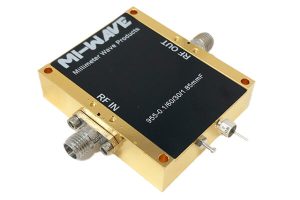
X-band, spanning roughly 8.2 GHz to 12.4 GHz, carries some of the most demanding radar and satellite traffic in use today. Naval and airborne radar, weather radar, air traffic control, and fixed satellite uplinks all rely on this range. Signals in these systems are often either extremely weak by the time they reach a receiver, or need a substantial boost before they leave a transmitter.
An amplifier is the component that does that work, and the right choice depends heavily on which side of the signal chain it sits on. A receive-side amplifier and a transmit-side amplifier are optimized for almost opposite goals, even though both fall under the same general category.
This guide walks through what these amplifiers do, the specifications that matter most depending on where they sit in the chain, and how to choose between a receive-focused and transmit-focused design for a given application.
What Does an X Band Amplifier Do
At its core, an amplifier increases the power of an RF signal without altering its frequency or modulation. In X-band systems, that job splits into two distinct roles depending on which end of the signal path the amplifier occupies.
Receive-Side: Low Noise Amplification
On the receive side, the priority is preserving a weak incoming signal without adding noise that would bury it further. Mi-Wave’s 955 Series X-band amplifier covers the full 8.2–12.4 GHz range and is built specifically for this front-end role, where noise figure, not raw output power, determines how well the receiver can pull a usable signal out of the noise floor.
Transmit-Side: Power Amplification
On the transmit side, the goal flips: deliver as much clean output power as possible while keeping distortion and spectral regrowth under control. Here, an RF power amplifier is optimized for output P1dB, saturated power, and gain rather than noise figure, since the signal is already strong by the time it reaches this stage.
Key Specifications to Evaluate
- Frequency range — confirm the exact X-band segment (or adjacent Xs-band, 10–15 GHz) your system operates in; amplifiers are band-specific.
- Noise figure (receive side) — the single most important number for front-end amplifiers; lower is better for weak-signal detection.
- Gain — how much amplification is applied; too little underperforms, too much risks instability or compression.
- Output power, P1dB and Psat (transmit side) — determines how much clean power the amplifier can deliver before compressing or distorting.
- VSWR and impedance matching — poor matching reflects energy back into the amplifier and degrades both gain and stability.
- DC bias requirements — voltage and current draw affect power budget and thermal design, especially in compact or airborne platforms.
How to Choose the Right X Band Amplifier for Your System
1. Decide Which Side of the Chain You’re Amplifying
This is the first fork in the decision tree. Receive-side placement calls for a noise-optimized X-band LNA; transmit-side placement calls for a power amplifier built for output and linearity. Trying to use one in place of the other rarely works well.
2. Match Frequency Coverage Precisely
Confirm the exact operating band — standard X-band, extended Xs-band, or a narrower custom slice — since amplifiers rated for the full 8.2–12.4 GHz range may trade off some gain flatness compared to units optimized for a narrower segment.
3. Size Power Handling to the Application
For transmit chains, size output power to the actual link budget, not just headline P1dB numbers. Reflected power during antenna mismatch conditions can push levels higher than steady-state operation suggests.
4. Confirm Interface and Mechanical Requirements
X-band amplifiers ship with coaxial or waveguide interfaces depending on the model. Match the connector or flange type, DC bias method, and environmental rating (temperature range, vibration, altitude) to the platform before finalizing a selection.
Common Applications
- Naval and airborne radar systems, where receive sensitivity directly affects detection range.
- Weather radar, requiring stable gain and low noise for consistent return signal interpretation.
- Air traffic control radar, where reliability and consistent performance matter as much as raw specs.
- Fixed satellite service (FSS) uplinks, where transmit-side amplifiers push signal to the satellite.
- RF test and measurement setups, where both amplifier types are used to characterize other components.
Final Thoughts
Treating X-band amplifier as a single category can lead to a mismatch between what a system needs and what gets specified. Once the receive-versus-transmit question is answered, most of the remaining decisions, frequency coverage, power handling, interface, follow naturally. Mi-Wave’s 955 Series spans both roles across the X-band and adjacent frequency ranges, and the engineering team can help match a stock configuration or a custom design to a specific radar, SatCom, or test application.
