
Description:
Mi-Wave’s E-Plane Waveguide Bends are high-precision waveguide transmission components designed to provide accurate directional changes and offsets in microwave and millimeter-wave systems. Available in the 660, 661, 662, and 665 Series, these bends are precision-formed waveguide sections manufactured to standard bend angles of 30°, 45°, 60°, and 90°.
E-plane bends change the direction of RF energy in the plane of the electric field, allowing engineers to route waveguide transmission lines through compact assemblies, test fixtures, and system enclosures while preserving signal integrity. Manufactured to rigid specifications, these components are designed to minimize detrimental effects on overall system VSWR and maintain reliable waveguide performance.
Mi-Wave E-Plane Bends are available in a wide range of frequencies supporting a broad range of microwave and millimeter-wave applications. Special angles, bend radii, lengths, and configurations can also be developed for custom system requirements.
The standard models shown represent only part of Mi-Wave’s broader product capabilities. Custom configurations are available to support specific frequency bands, interfaces, and application requirements, enabling optimized solutions for specialized RF, microwave, and millimeter-wave systems.
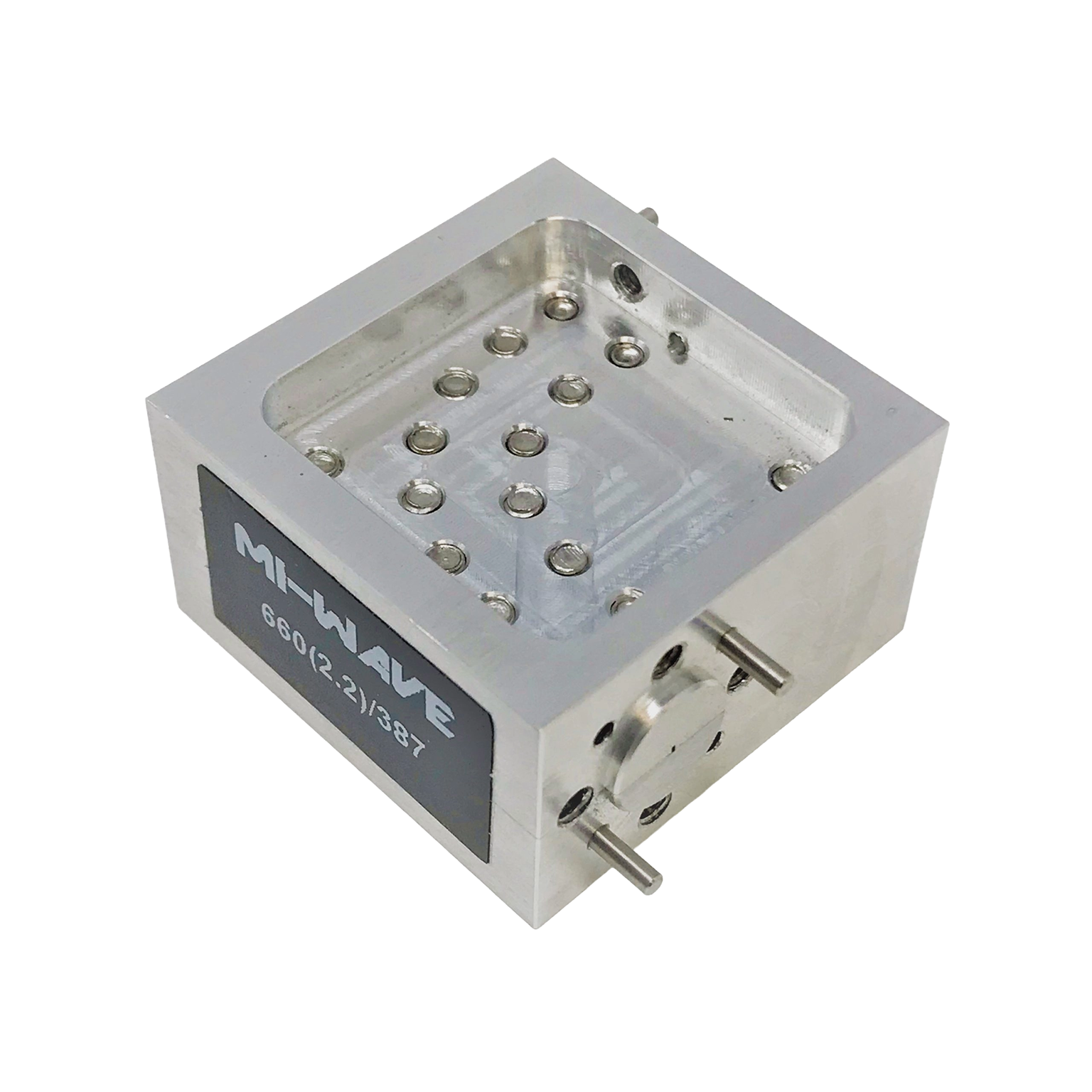
*Actual product may be different from the image shown per customers specifcations
*All data presented is collected from a sample lot.
* Actual data may vary unit to unit, slightly.
*All testing was performed under +25 °C case temperature.
*Consult factory to confirm if material, plating, size, shape, orientation and any electrical parameter is critical for the application as website information is for reference only.
*Millimeter Wave Products, Inc. reserves the right to change the information presented on website without notice as we continue to enhance the performance and design of our products.
Features & Performance Characteristics
Precision E-Plane Waveguide Routing
E-plane bends allow waveguide transmission lines to change direction in the electric field plane while maintaining controlled RF behavior. This makes them useful for compact layouts, offset assemblies, and high-frequency routing where coaxial solutions may introduce excessive loss.
Standard Bend Angles
Mi-Wave offers standard E-plane bends in 30°, 45°, 60°, and 90° configurations. This gives engineers flexibility when designing waveguide paths for laboratory setups, test fixtures, and integrated RF systems.
Broad Frequency Coverage
Available from in a wide range of frequencies, these bends support microwave and millimeter-wave systems across a wide range of standard waveguide bands.
Low VSWR Impact
Manufactured to precise mechanical tolerances, Mi-Wave E-plane bends are designed to minimize reflections and reduce unwanted effects on system VSWR.
Custom Bend Configurations
Special angles, bend radii, and mechanical layouts can be developed for custom applications where standard waveguide geometry does not meet system constraints.
Rigid Waveguide Construction
Each bend is manufactured as a precision waveguide section to provide repeatable mechanical alignment and stable RF performance.
How E-Plane Bends Work
An E-plane waveguide bend changes the direction of propagation by curving or angling the waveguide in the plane associated with the electric field. As RF energy travels through the bend, the waveguide geometry guides the electromagnetic field around the change in direction while maintaining the supported propagation mode.
Because bends introduce a physical discontinuity in the waveguide path, their geometry must be carefully controlled. Bend angle, radius, wall finish, flange alignment, and dimensional accuracy all affect RF performance. Poorly formed bends can increase reflections, create mode conversion, or raise VSWR.
Mi-Wave E-plane bends are manufactured to precise tolerances to help maintain smooth transmission through the bend and reduce mismatch effects. When properly selected and installed, they allow engineers to route waveguide lines efficiently while preserving system performance.
Applications
Waveguide Transmission Line Routing
E-plane bends provide controlled directional changes in waveguide runs, allowing RF energy to be routed around mechanical constraints while maintaining waveguide continuity.
RF Test and Development Systems
These bends are commonly used in laboratory and development environments where waveguide routing must be adjusted for measurement equipment, test fixtures, antennas, or device-under-test positioning.
Microwave and Millimeter-Wave Assemblies
In high-frequency subsystems, E-plane bends help fit waveguide paths into compact mechanical layouts without requiring complex transitions or unnecessary additional components.
Antenna Feed and Front-End Systems
E-plane bends can be integrated into antenna feed networks and RF front ends where precise waveguide routing is needed between components.
Custom RF System Integration
Special bend geometries can be designed for systems requiring non-standard angles, spacing, or mechanical alignment.
Frequently Asked Questions (FAQ)
What is an E-plane waveguide bend?
An E-plane waveguide bend is a waveguide section that changes the direction of RF propagation in the plane of the electric field.
What bend angles are available?
Mi-Wave E-plane bends are available in standard 30°, 45°, 60°, and 90° configurations.
What frequency range do these bends support?
E-plane bends are available from 12.4 GHz to 325 GHz, depending on waveguide size and configuration.
What is the difference between an E-plane bend and an H-plane bend?
An E-plane bend changes direction in the plane of the electric field, while an H-plane bend changes direction in the plane of the magnetic field.
Do waveguide bends affect VSWR?
Any bend can introduce reflections if not manufactured properly. Mi-Wave E-plane bends are precision-manufactured to minimize detrimental effects on system VSWR.
Can custom bend angles be made?
Yes. Special angles, radii, offsets, and configurations can be developed for custom applications.
Where are E-plane bends used?
They are used in waveguide transmission lines, RF test systems, antenna feed assemblies, mmWave subsystems, and custom RF layouts.
E-Plane Waveguide Bend Calculators
These calculators help estimate insertion loss impact, effective path length, phase shift, and return loss when routing RF signals through E-plane waveguide bends.
Insertion Loss Through Bend
Estimate output power after waveguide bend insertion loss.
Wavelength Calculator
Calculate free-space wavelength for phase and path calculations.
Phase Shift Through Bend
Estimate phase shift based on electrical path length.
Arc Length of Bend
Estimate arc length for a given bend angle and radius.
VSWR to Return Loss
Convert VSWR to return loss to evaluate mismatch through the bend.
Glossary of E-Plane Waveguide Bend Terms
E-Plane Bend
A waveguide bend that changes the direction of propagation in the electric field plane of the waveguide.
E-Plane
The plane associated with the electric field orientation inside a rectangular waveguide.
Waveguide Bend
A shaped waveguide section used to change the direction of an RF transmission path.
Bend Angle
The angle through which the waveguide path changes direction, such as 30°, 45°, 60°, or 90°.
Bend Radius
The radius of curvature used in the bend, which can affect reflections and mode behavior.
VSWR
Voltage Standing Wave Ratio, a measure of impedance matching and reflected power.
Mode Conversion
The unwanted conversion of energy from one waveguide mode to another due to discontinuities or improper geometry.
Waveguide Transmission Line
A metallic structure used to guide microwave and millimeter-wave signals with low loss.
Flange Alignment
The mechanical alignment of waveguide flanges, important for reducing discontinuities and maintaining RF performance.
Millimeter-Wave
Frequencies generally above 30 GHz, where waveguide precision becomes especially important.
| Model | Band | Frequency (GHz) | Degree | Plane | VSWR (Typ) | RF Ports | Link |
|---|---|---|---|---|---|---|---|
| 66(0/1/2/5)X/39 | X-Band | 8.2-12 | 90°, 30°, 60°, 45° | E-Plane | 1.06:1 | WR-90 Waveguide, UG-39/U Flange | |
| 66(0/1/2/5)K/595 | K-Band | 18-26.5 | 90°, 30°, 60°, 45° | E-Plane | 1.06:1 | WR-42 Waveguide, UG-595/U Flange | |
| 66(0/1/2/5)A/599 | Ka-Band | 26.5-40 | 90°, 30°, 60°, 45° | E-Plane | 1.06:1 | WR-28 Waveguide, UG-599/U Flange | |
| 66(0/1/2/5)B/383 | Q-Band | 33-50 | 90°, 30°, 60°, 45° | E-Plane | 1.06:1 | WR-22 Waveguide, UG-383/U Flange | |
| 66(0/1/2/5)U/383 | U-Band | 40-60 | 90°, 30°, 60°, 45° | E-Plane | 1.12:1 | WR-19 Waveguide, UG-383/U Flange | |
| 66(0/1/2/5)V/385 | V-Band | 50-75 | 90°, 30°, 60°, 45° | E-Plane | 1.15:1 | WR-15 Waveguide, UG-385/U Flange | |
| 66(0/1/2/5)E/387 | E-Band | 60-90 | 90°, 30°, 60°, 45° | E-Plane | 1.15:1 | WR-12 Waveguide, UG-387/U Flange | |
| 66(0/1/2/5)W/387 | W-Band | 75-110 | 90°, 30°, 60°, 45° | E-Plane | 1.15:1 | WR-10 Waveguide, UG-387/U Flange | |
| 66(0/1/2/5)F/387 | F-Band | 90-140 | 90°, 30°, 60°, 45° | E-Plane | 1.15:1 | WR-8 Waveguide, UG-387/U Flange | |
| 66(0/1/2/5)D/387 | D-Band | 110-170 | 90°, 30°, 60°, 45° | E-Plane | 1.15:1 | WR-6 Waveguide, UG-387/U-M Flange | |
| 66(0/1/2/5)G/387 | G-Band | 140-220 | 90°, 30°, 60°, 45° | E-Plane | 1.15:1 | WR-5 Waveguide, UG-387/U Flange | |
| 66(0/1/2/5)H/387 | H-Band | 170-260 | 90°, 30°, 60°, 45° | E-Plane | 1.15:1 | WR-4 Waveguide, UG-387/U Flange | |
| 66(0/1/2/5)J/387 | J-Band | 220-325 | 90°, 30°, 60°, 45° | E-Plane | 1.15:1 | WR-3 Waveguide, UG-387/U Flange | |
| 66(0/1/2/5(2.2)/387 | WR-2.2 | 325-500 | 90°, 30°, 60°, 45° | E-Plane | 1.15:1 | WR-2.2 Waveguide,UG-387/U-M Flange |
Return to Bends & Twists Page