
Mi-Wave Series 261 standard gain horn antennas support a broad range of Ka-Band, Q-Band, and V-Band frequency allocations commonly used in modern satellite communications (SatCom) systems. These antennas are designed to provide accurate, repeatable gain and stable radiation patterns across satellite bands used for gateway operations, feeder links, and system validation.
Mi-Wave gain horns support a broad range of Ka-Band, Q-Band, and V-Band frequency ranges commonly used in SatCom systems, including 37.5–39.5 GHz, 39.5–42.5 GHz, 37.5–42.0 GHz, 47.2–50.2 GHz, and 50.4–51.4 GHz. These ranges are widely used in gateway testing, feeder link evaluation, HTS system development, radar and sensing applications, and advanced RF research environments.
These frequency ranges are widely used in SatCom gateway testing, feeder link evaluation, high-throughput satellite (HTS) system development, and uplink/downlink performance validation. The stable, known gain characteristics of Mi-Wave standard gain horns make them ideal reference antennas for verifying system performance across these critical satellite bands.
Mi-Wave gain horn antennas are compatible with standard WR waveguide interfaces corresponding to these bands, allowing seamless integration into SatCom RF chains, including HPAs, LNAs, upconverters, downconverters, and precision test instrumentation.
Note: The standard gain horn antennas shown on this website represent only a portion of Mi-Wave’s manufacturing capabilities. Mi-Wave designs and builds additional standard gain horn configurations beyond those listed, including custom frequency ranges, waveguide interfaces, polarization options, and mechanical form factors. Consult with Mi-Wave to discuss your specific SatCom requirements.

| Model | Minimum Frequency (GHz) | Maximum Frequency (GHz) | Gain (dBi) typical | Polarization | Beamwidth, E-Plane (db) | Beamwidth, H-Plane (dB) | Side Lobes (E-Plane)(dB) | Side Lobes (H-Plane) (dB) | RF Ports | LINK |
|---|---|---|---|---|---|---|---|---|---|---|
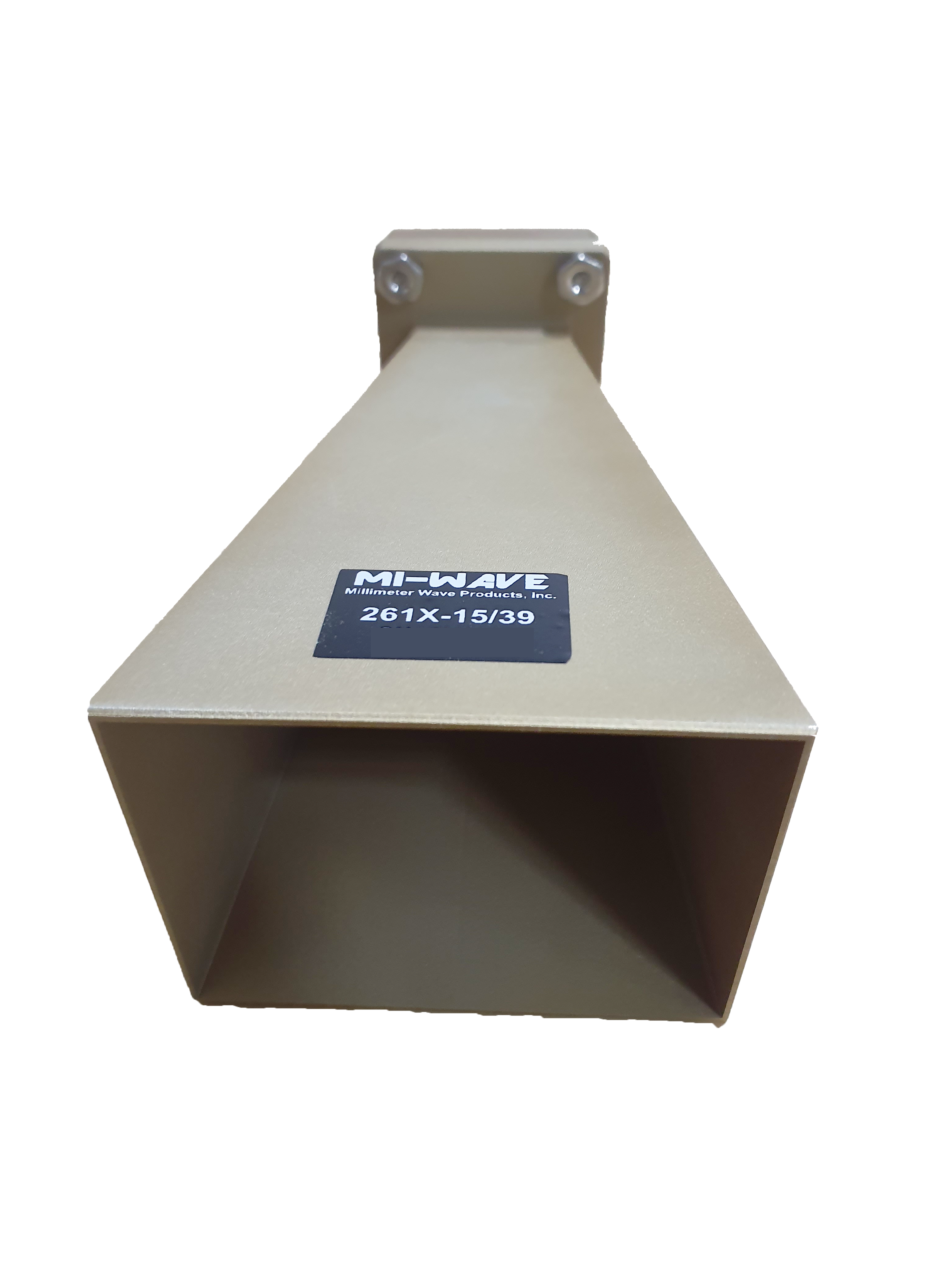
| 261X-15/39 | 8.2 | 12.4 | 15 | Linear | 29.3 | 29 | 20 | 20 | WR-90 Waveguide with UG-39 Flange | |
| 261(75)-20/120 | 10 | 15 | 20 | Linear | 16.22 | 19.81 | 12 | 18 | WR-75 waveguide UBR - 120 / U | |
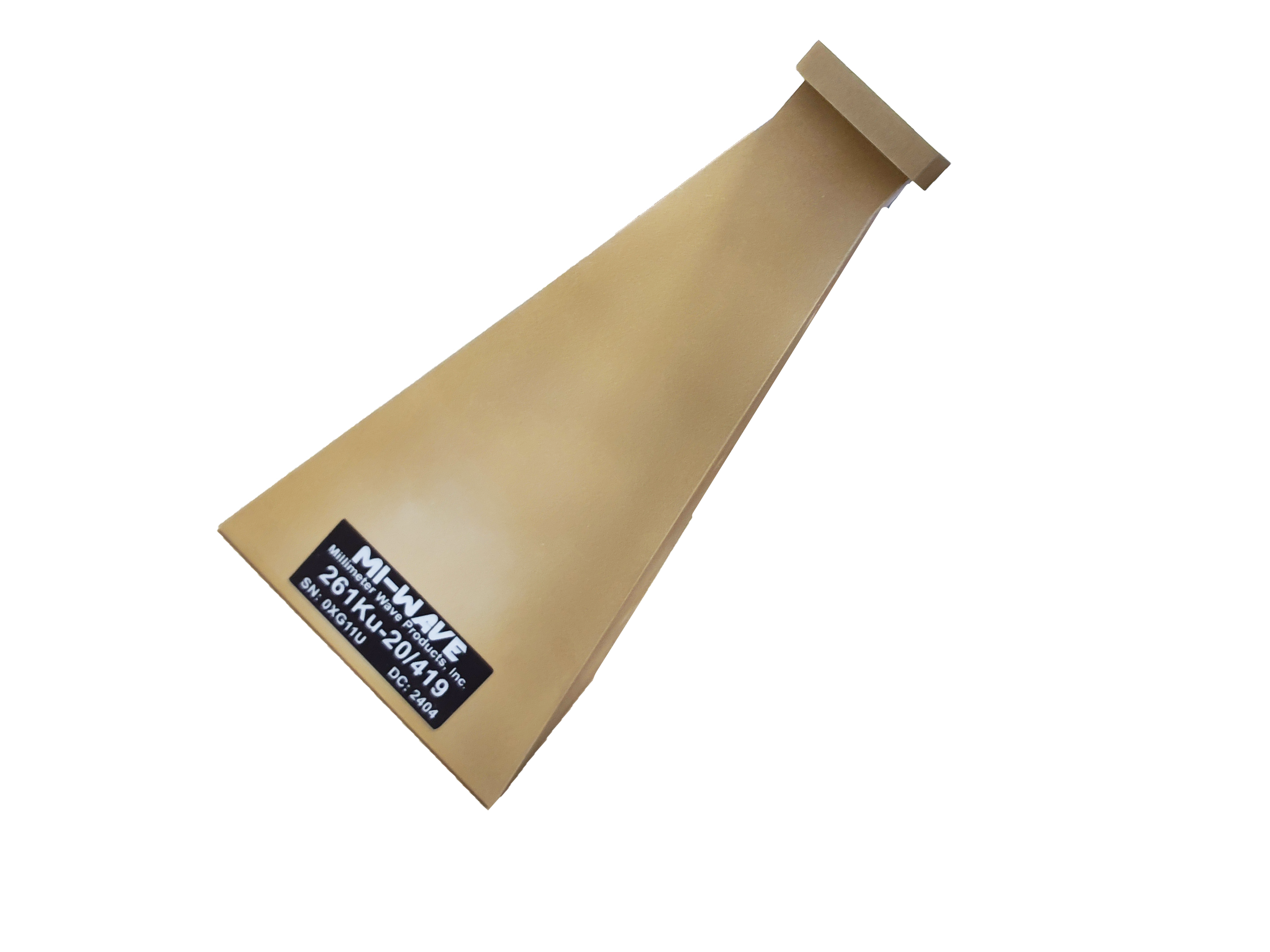
| 261Ku-20/419 | 12 | 18 | 20 | Linear | 16.90 | 17.80 | 16 | 18 | WR-90 Waveguide port UG-419/U Flange | |
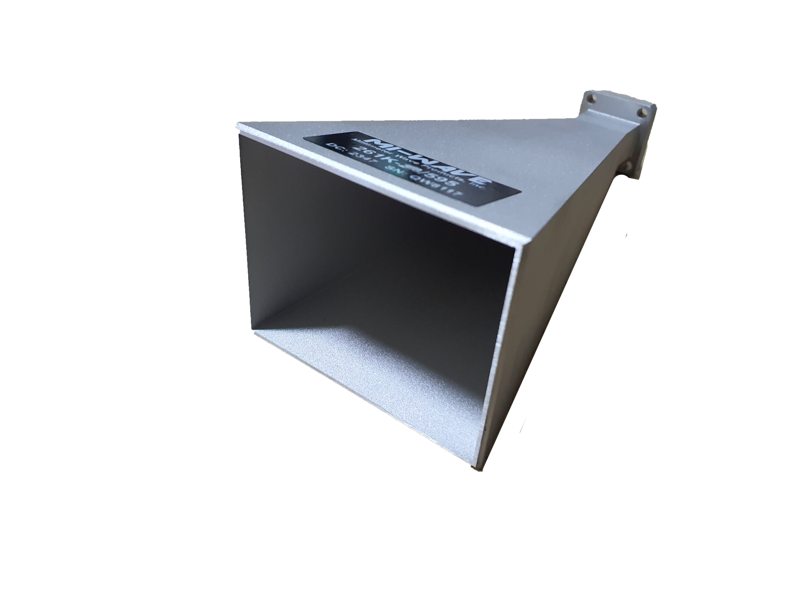
| 261K-10/595 | 18 | 26.5 | 10 | Linear | 55 | 57 | 17 | 25 | WR-42 Waveguide UG-595/U Flange | |
| 261K-15/595 | 18 | 26.5 | 15 | Linear | 19 | 21 | 20 | 23 | WR-42 Waveguide UG-595/U Flange | |
| 261K-20/595 | 18 | 26.5 | 20 | Linear | 19 | 21 | 20 | 20 | WR-42 Waveguide UG-595/U Flange | |
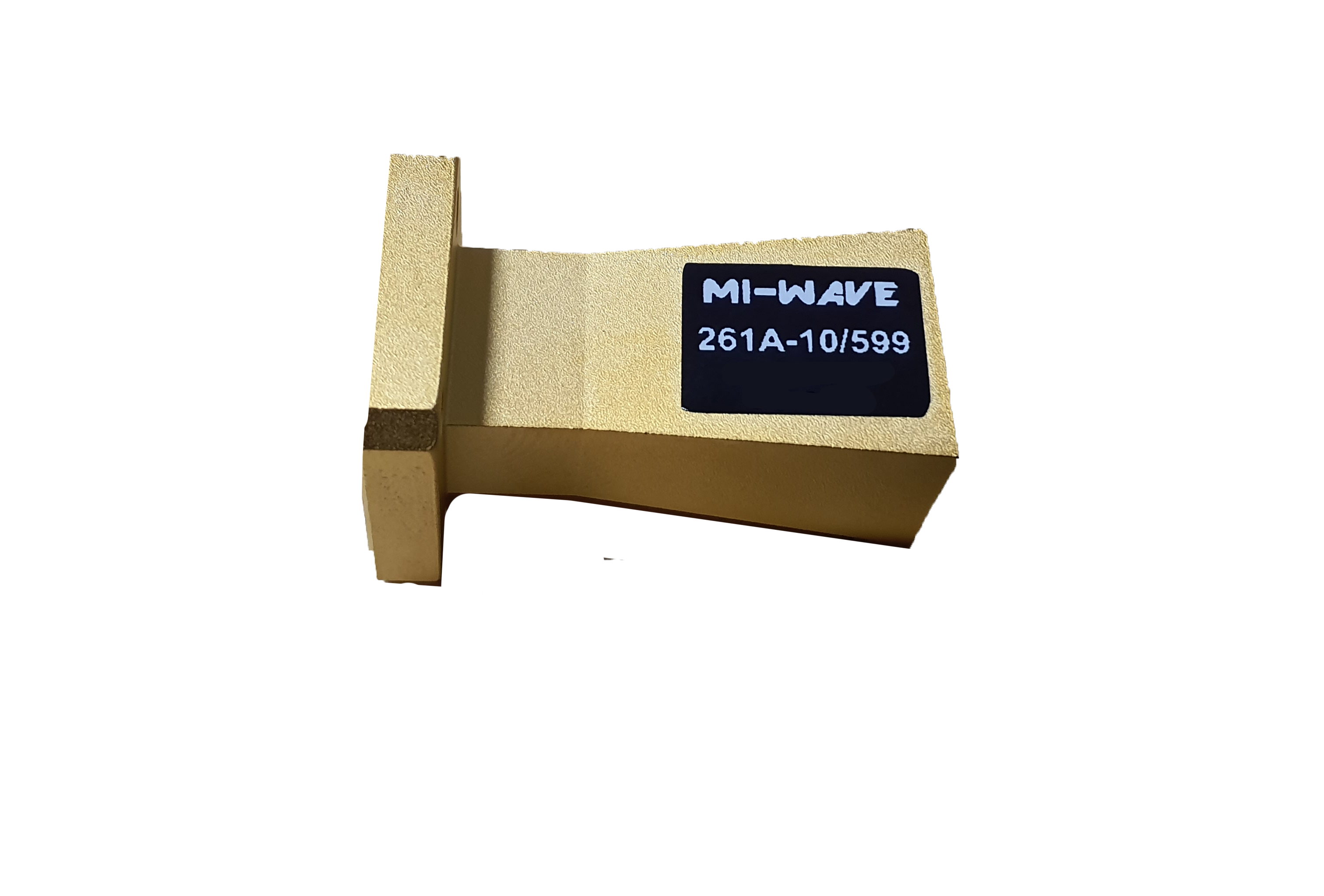
| 261A-10/599 | 26.5 | 40 | 10 | Linear | 56 | 54 | 20 | 20 | WR-28 Waveguide UG-599/U Flange | |
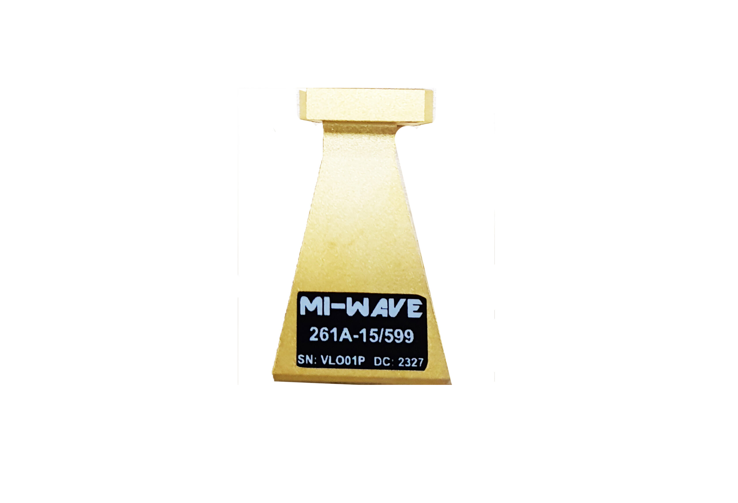
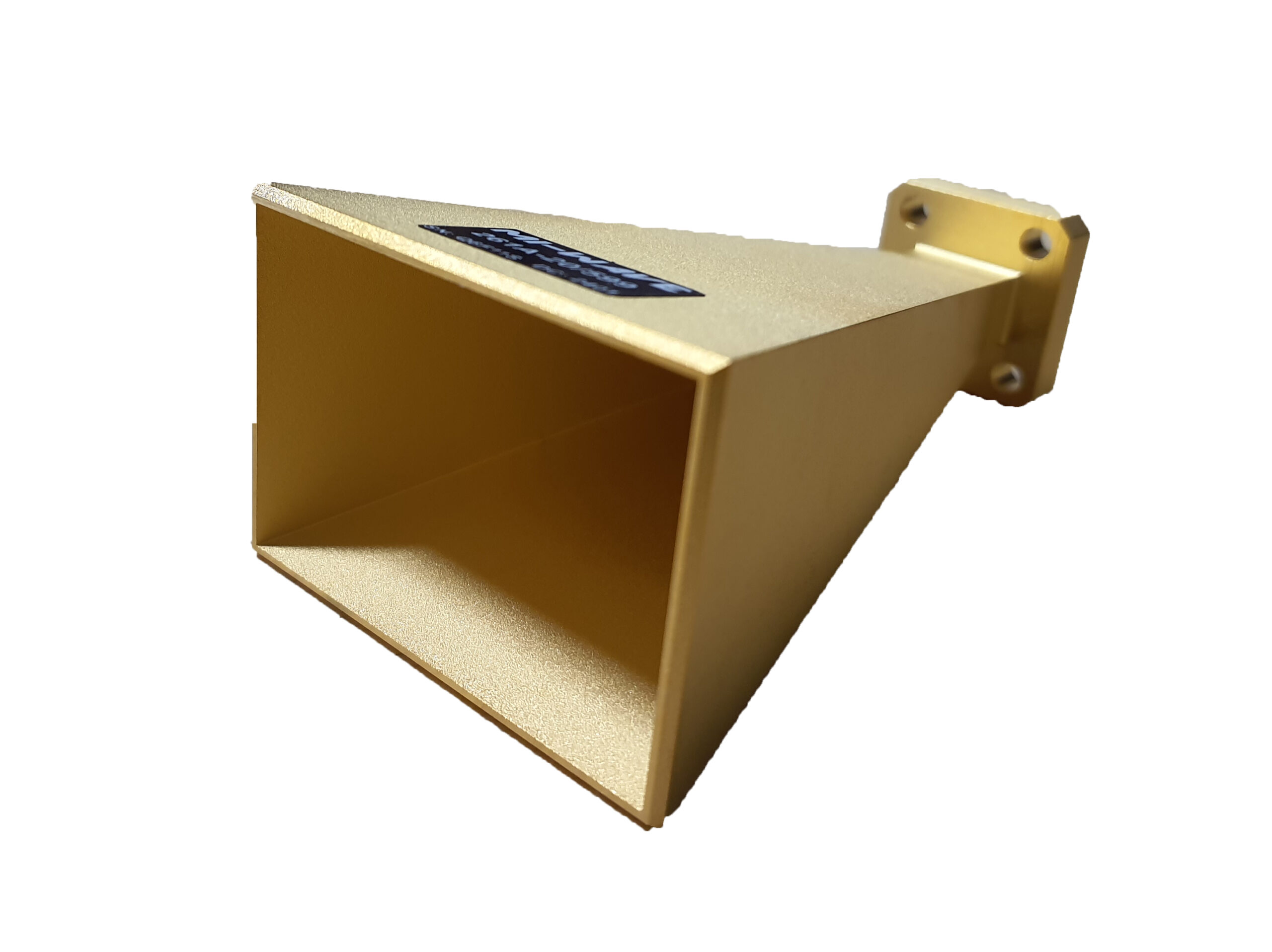
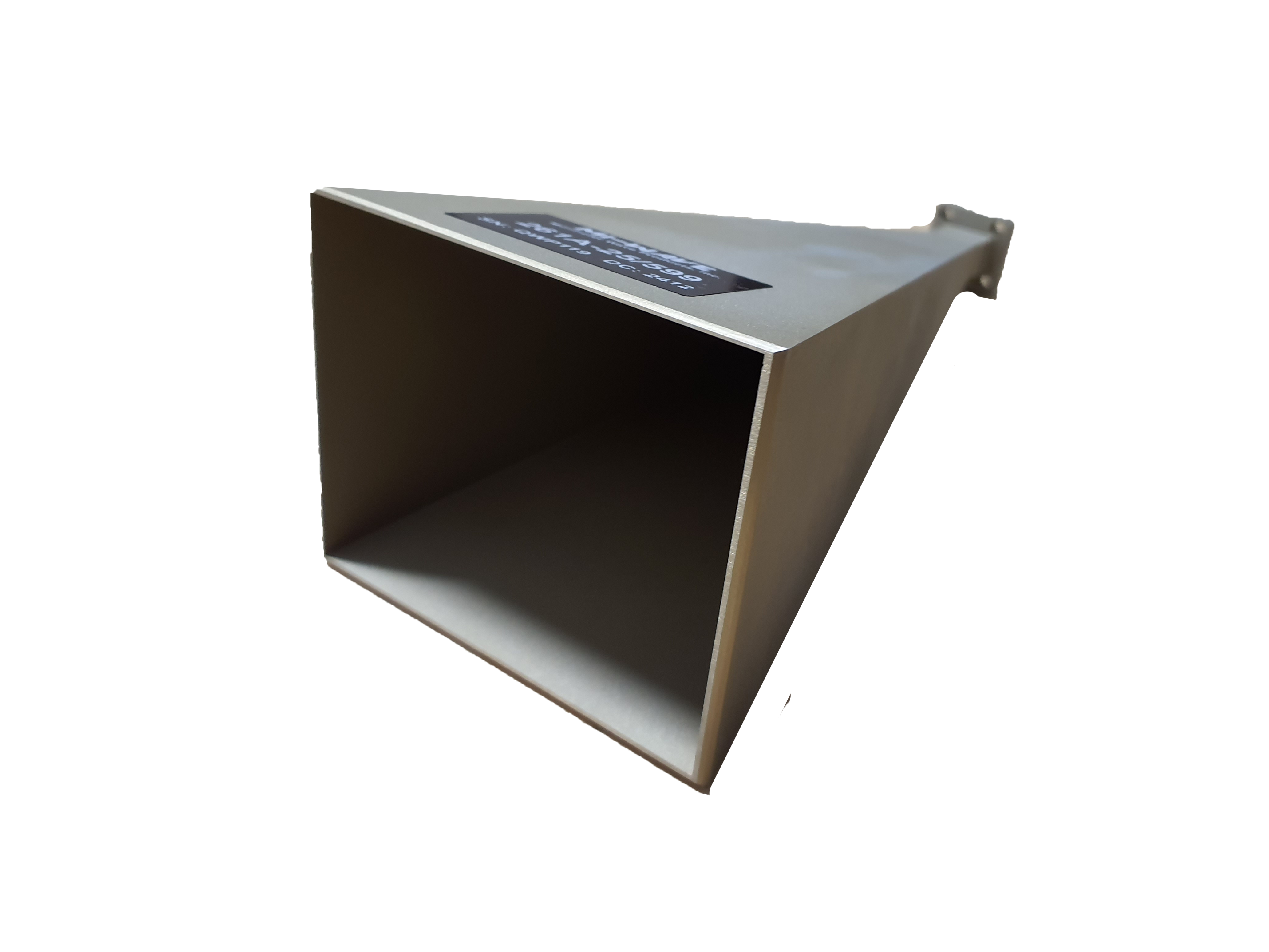
| 261A-15/599 | 26.5 | 40 | 15 | Linear | 33 | 33 | 20 | 20 | WR-28 Waveguide UG-599/U Flange | |
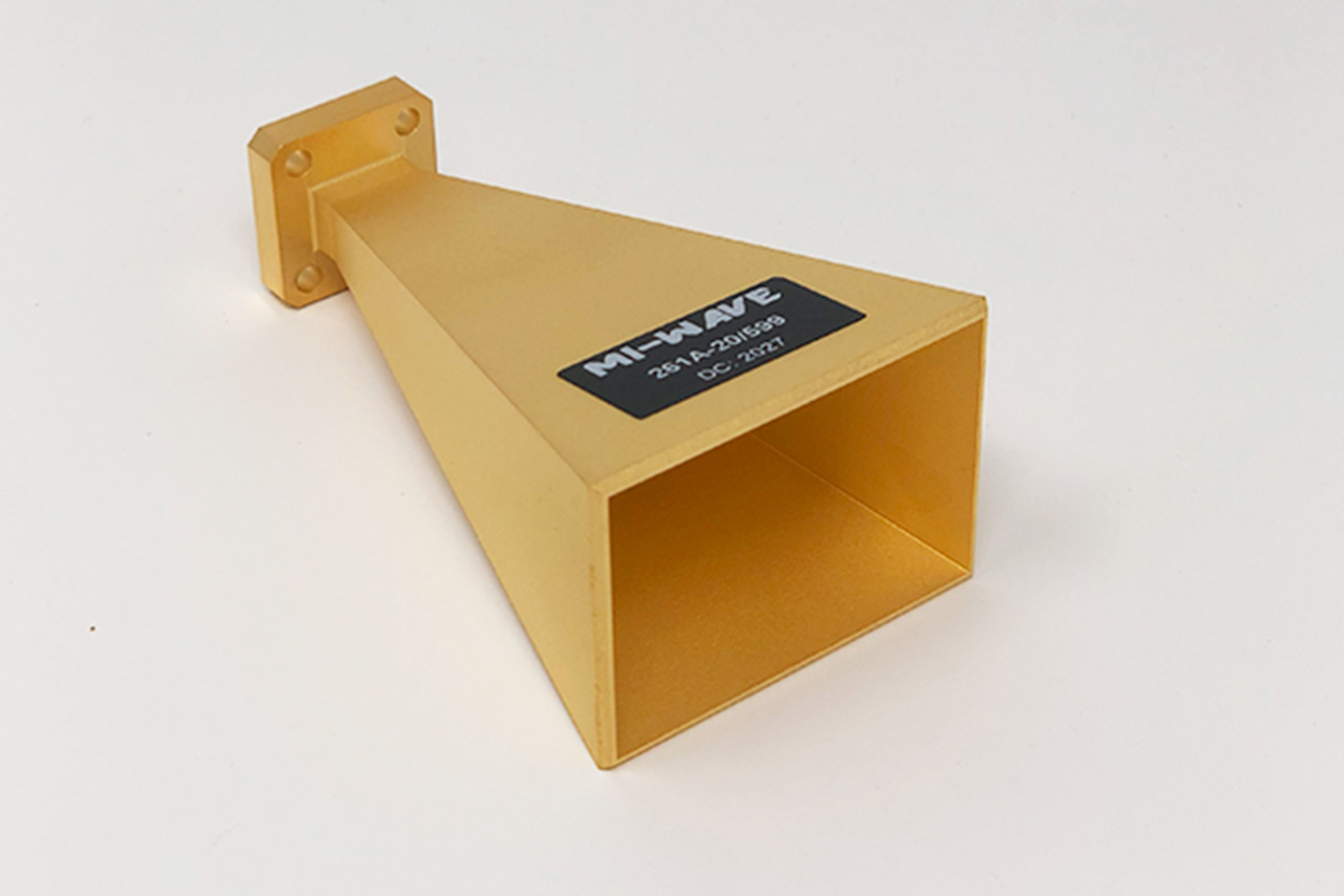
| 261A-20/599 | 26.5 | 40 | 20 | Linear | 16.57 | 16.58 | 20 | 20 | WR-28 Waveguide UG-599/U Flange | |
| 261A-25/599 | 26.5 | 40 | 25 | Linear | 7 | 9 | 20 | 20 | WR-28 Waveguide UG-599/U Flange | |
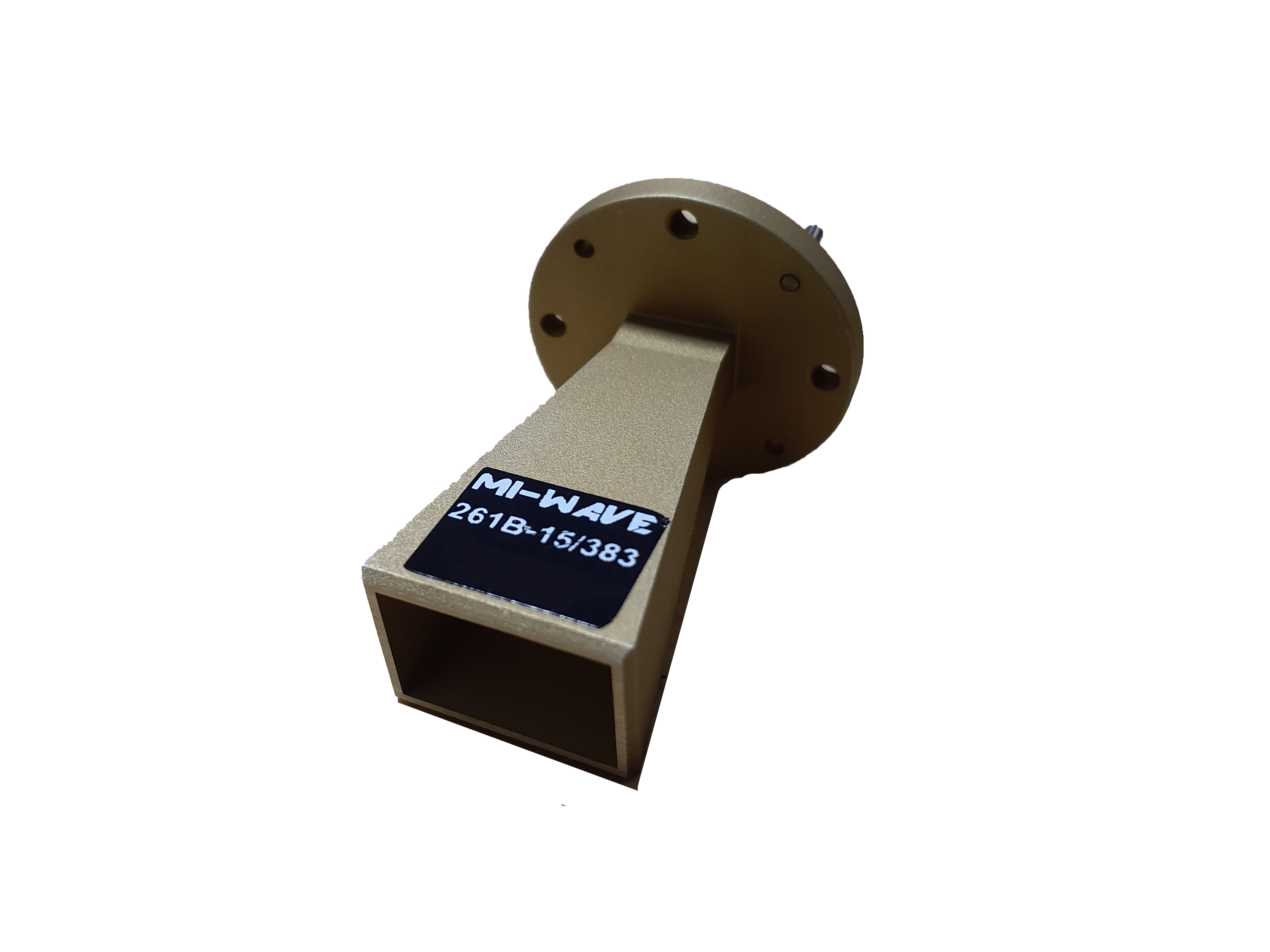
| 261B-15/383 | 33 | 50 | 15 | Linear | 39.81 | 25.9 | 20 | 20 | WR-22 Waveguide UG-383/U Flange | |
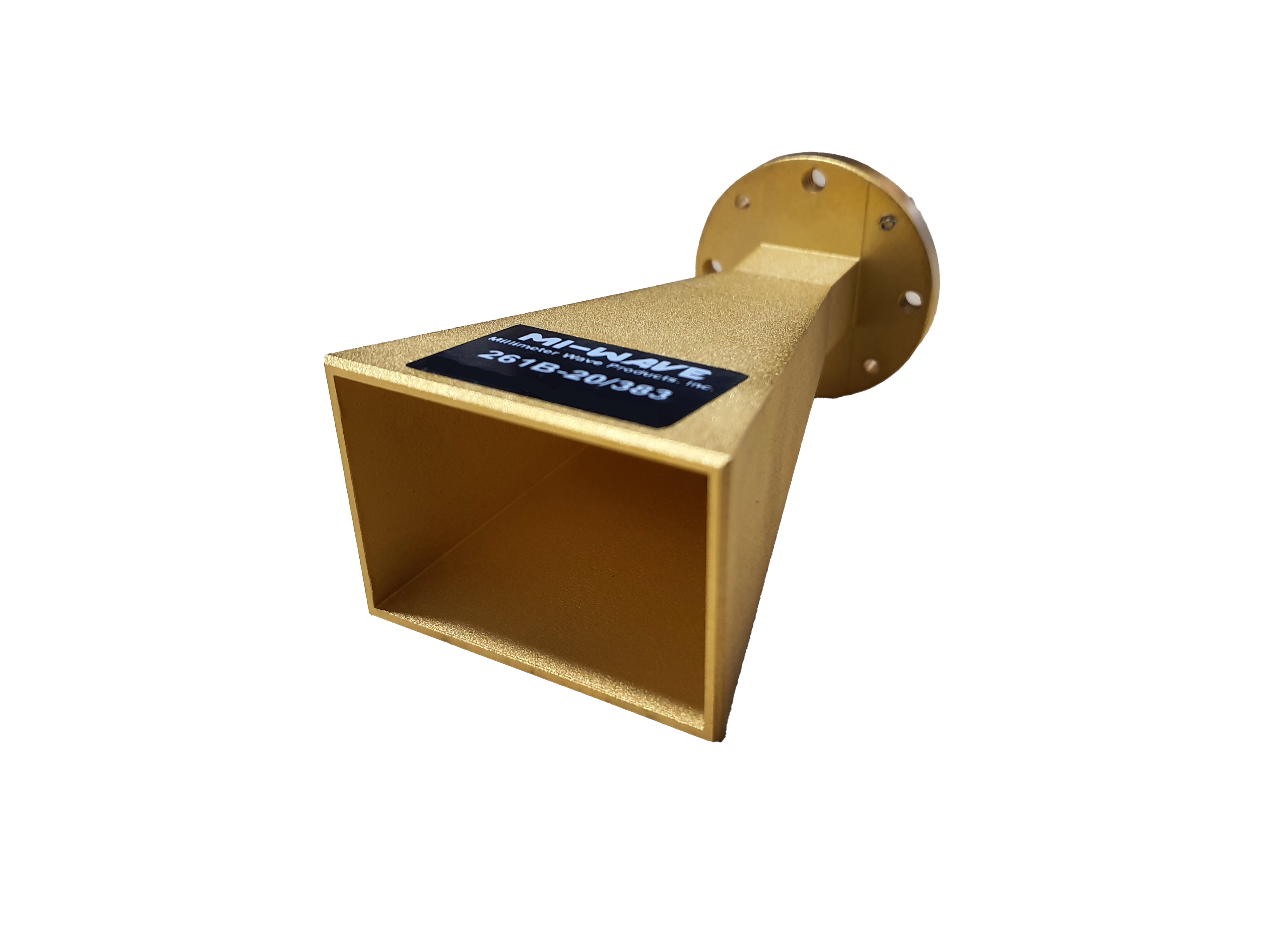
| 261B-20/383 | 30 | 50 | 20 | Linear | 15 | 16 | 20 | 20 | WR-22 Waveguide UG-383/U Flange | |
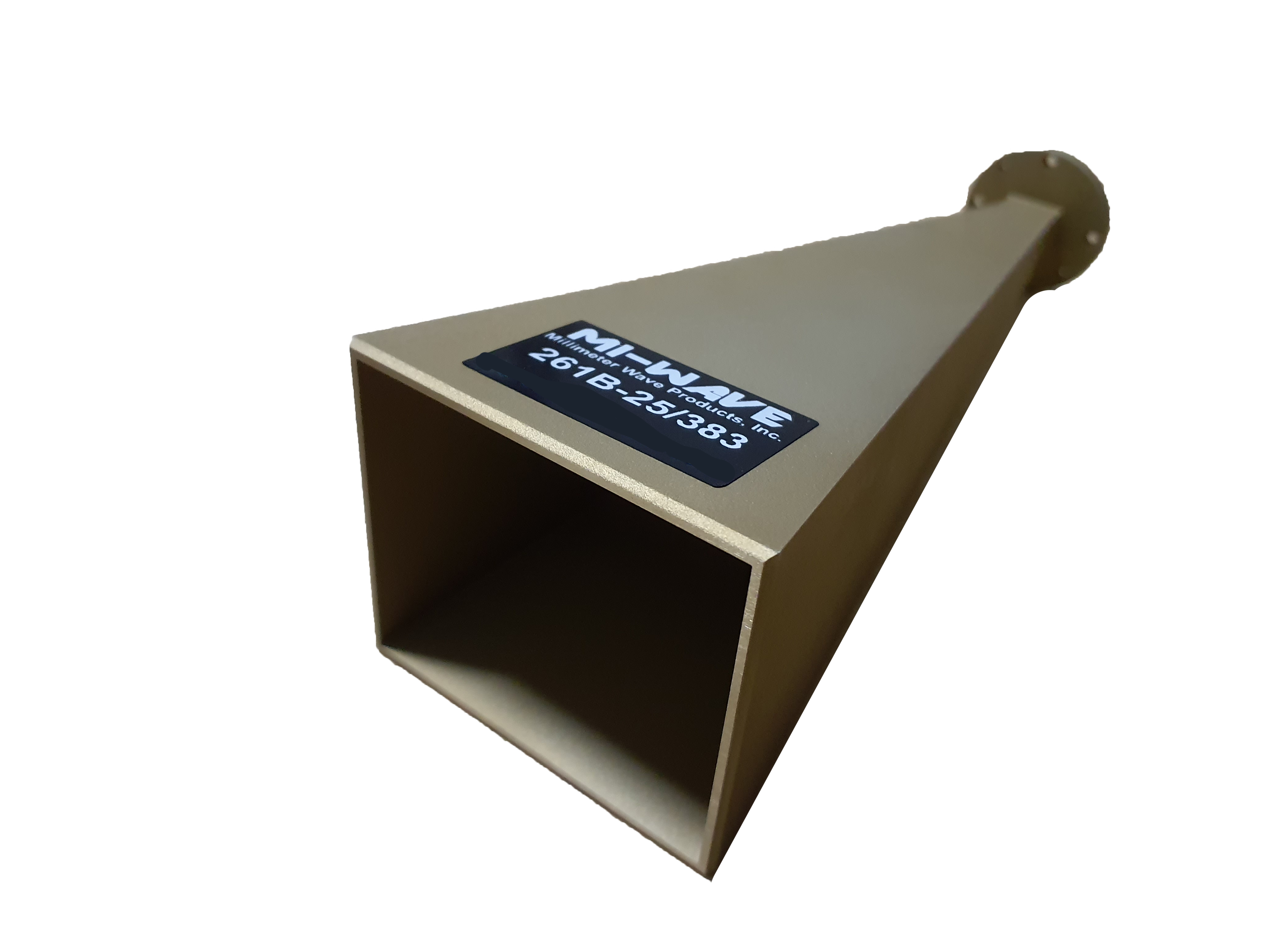
| 261B-25/383 | 33 | 50 | 25 | Linear | 7 | 9 | 20 | 20 | WR-22 Waveguide UG-383/U Flange | |
| 261U-10/383 | 40 | 60 | 10 | Linear | 55 | 55 | 20 | 20 | WR-19 Waveguide UG-383/U-M Flange | |
| 261U-15/383 | 40 | 60 | 15 | Linear | 32 | 32 | 14 | 20 | WR-19 Waveguide UG-383/U-M Flange | |
| 261U-20/383 | 40 | 60 | 20 | Linear | 14 | 16 | 14 | 30 | WR-19 Waveguide UG-383/U-M Flange | |
| 261U-25/383 | 40 | 60 | 25 | Linear | 9 | 10 | 20 | 20 | WR-19 Waveguide UG-383/U-M Flange | |
| 261V-10/385 | 50 | 75 | 10 | Linear | 55 | 55 | 20 | 20 | WR-15 Waveguide UG-385/U-M Flange | |
| 261V-15/385 | 50 | 75 | 15 | Linear | 29 | 32 | 20 | 20 | WR-15 Waveguide UG-385/U-M Flange | |
| 261V-20/385 | 50 | 75 | 20 | Linear | 14 | 15 | 20 | 20 | WR-15 Waveguide UG-385/U Flange | |
| 261V-25/385-FL | 50 | 75 | 25 | Linear | 9 | 10 | 20 | 20 | WR-15 Waveguide UG-385/U Flange | |
| 261E-10/387 | 60 | 90 | 10 | Linear | 55 | 55 | 20 | 20 | WR-12 Waveguide UG-387/U Flange | |
| 261E-15/387 | 60 | 90 | 15 | Linear | 30 | 32 | 20 | 20 | WR-12 Waveguide UG-387/U Flange | |
| 261E-20/387 | 60 | 90 | 20 | Linear | 14 | 15 | 20 | 20 | WR-12 Waveguide UG-387/U Flange | |
| 261E-25/387 | 60 | 90 | 25 | Linear | 9 | 10 | 20 | 20 | WR-12 Waveguide UG-387/U Flange | |
| 261W-10/387 | 75 | 110 | 10 | Linear | 51.76 | 52 | 2 | 25 | WR-10 Waveguide UG-387/U-M Flange | |
| 261W-15/387 | 75 | 110 | 15 | Linear | 32 | 32 | 14 | 25 | WR-10 Waveguide UG-387/U-M Flange | |
| 261W-20/387 | 75 | 110 | 20 | Linear | 16 | 18 | 20 | 20 | WR-10 Waveguide UG-387/U-M Flange | |
| 261W-25/387-FL | 75 | 110 | 25 | Linear | 9 | 10 | 20 | 20 | WR-10 Waveguide UG-387/U-M Flange | |
| 261F-10/387 | 90 | 140 | 10 | Linear | 53 | 55 | 19 | 22 | WR-08 Waveguide UG-387/U-M Flange | |
| 261F-15/387 | 90 | 140 | 15 | Linear | 29.73 | 33.67 | 14 | 25 | WR-08 Waveguide UG-387/U-M Flange | |
| 261F-20/387 | 90 | 140 | 20 | Linear | 16 | 18 | 14 | 30 | WR-08 Waveguide UG-387/U-M Flange | |
| 261F-25/387 | 90 | 140 | 25 | Linear | 9 | 10 | 12 | 15 | WR-08 Waveguide UG-387/U-M Flange | |
| 261D-15/387 | 110 | 170 | 15 | Linear | 33 | 31 | 20 | 20 | WR-06 Waveguide UG-387/U-M Flange | |
| 261D-20/387 | 110 | 170 | 20 | Linear | 17 | 18 | 20 | 20 | WR-06 Waveguide UG-387/U-M Flange | |
| 261D-25/387 | 110 | 170 | 25 | Linear | 25 | 25.5 | 20 | 20 | WR-06 Waveguide UG-387/U-M Flange | |
| 261G-10/387 | 140 | 220 | 10 | Linear | 56 | 54 | 19 | 21 | WR-05 Waveguide UG-387/U-M Flange | |
| 261G-15/387 | 140 | 220 | 15 | Linear | 33.41 | 31.9 | 17 | 23 | WR-05 Waveguide UG-387/U-M Flange | |
| 261G-20/387 | 140 | 220 | 20 | Linear | 13 | 13 | 12 | 25 | WR-05 Waveguide UG-387/U-M Flange | |
| 261G-25/387 | 140 | 220 | 25 | Linear | 8.9 | 10.28 | 20 | 20 | WR-05 Waveguide UG-387/U-M Flange | |
| 261H-25/387 | 170 | 260 | 25 | Linear | 10 | 10 | WR-04 Waveguide UG-387/U Flange | |||
| 261J-15/387 | 220 | 325 | 15 | Linear | 35 | 38 | 14 | 17 | WR-3 Waveguide UG-387/U-M Flange | |
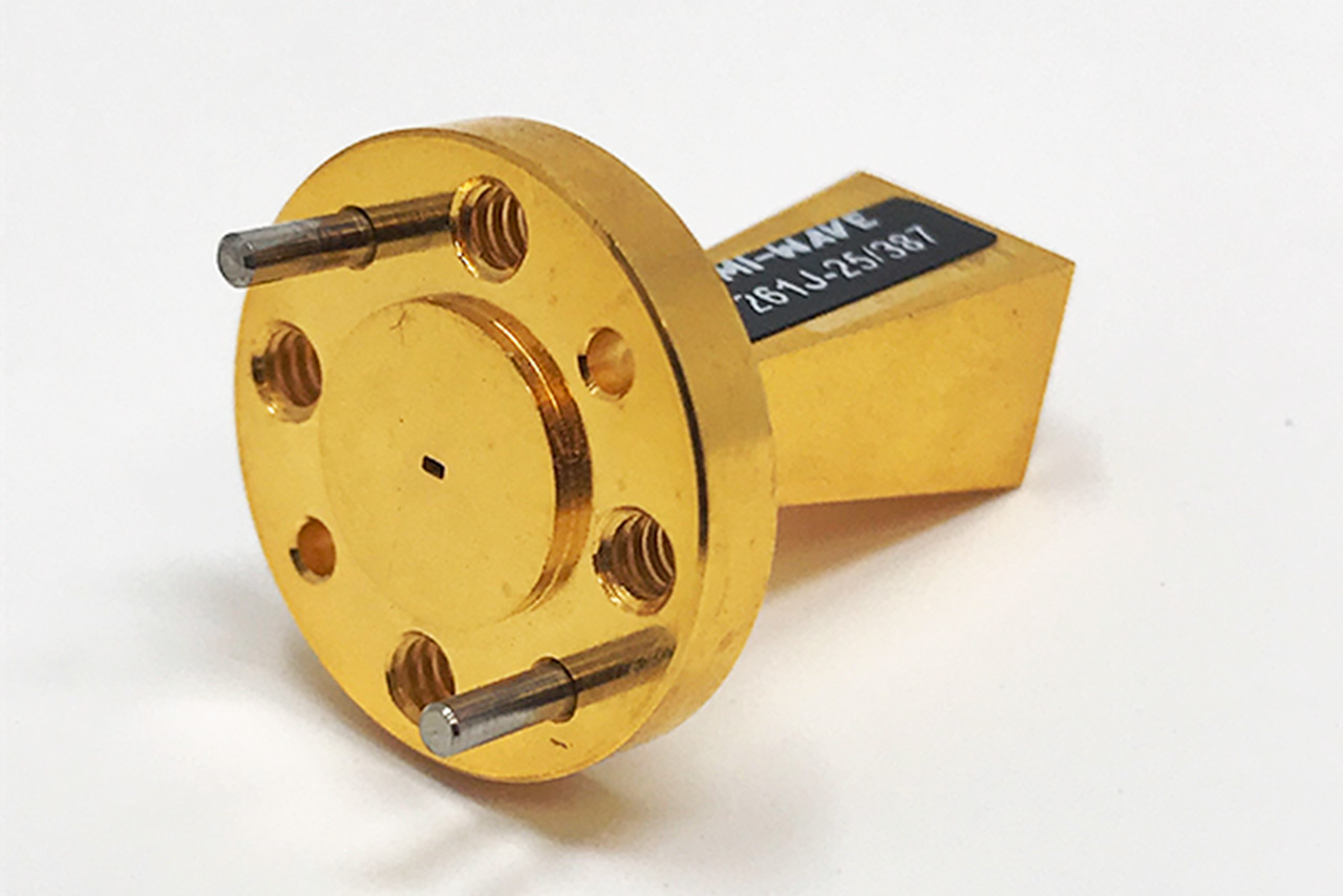
| 261J-25/387 | 220 | 325 | 25 | Linear | 9 | 10 | 20 | 20 | WR-3 Waveguide UG-387/U-M Flange | |
| 261(2.8)-25/387 | 260 | 400 | 25 | Linear | 26.18 | 25.8 | 20 | 20 | WR-2.8 Waveguide UG-387/U-M Flange | |
| 261(2.2)/387 | 325 | 500 | 25 | Linear | 13 | 15 | 22 | 23 | WR-2.2 Waveguide UG-387/U-M Flange | |
| 261(1.5)-25/387 | 500 | 750 | 25 | Linear | 22 | 23 | WR-1.5 Waveguide UG-387/U-M Flange |
Your Content Goes Here
Mi-Wave’s 261 Series standard gain horn antennas are created with the end consumer in mind. We know you need and demand the absolute best when it comes to horn antennas and we look to provide you with the best solutions possible. We can customize horn antennas for all your needs.
• Other gain values available upon request (ex: 10 dB, 15 dB, 20 dB, etc.)
Standard gain horn antennas can be ordered with a waveguide to coax adapter attached to it, or can be built with a custom-configured connector. Our broadband waveguide horn antennas have frequency capabilities ranging from 5 GHz to 40 GHz depending on type and needs. Our RF and microwave gain horn antennas are RoHS and REACH compliant.
Mi-Wave offers the broadest selection as we are the factory source that builds gain horns for organizations globally. Our expert sales engineers are always here to assist you.
Select Your Frequency Band
Click on the frequency band you’re interested in for specific gain horn antenna information.
Why Choose Mi-Wave for SatCom
Mi-Wave is a trusted manufacturer of RF, microwave, and millimeter-wave antennas and components, supporting satellite communication systems worldwide. Our Series 261 standard gain horn antennas are engineered to deliver measurement-grade accuracy, stable radiation patterns, and long-term reliability in demanding SatCom environments.
High-Frequency SatCom Engineering Expertise
With decades of experience in microwave and millimeter-wave design, Mi-Wave develops standard gain horn antennas optimized for known gain values, low VSWR, and controlled beamwidths, ensuring reliable SatCom link validation and system characterization.
Precision Manufacturing and Quality Control
Each Series 261 antenna is manufactured using precision machining and controlled assembly processes to ensure repeatable electrical performance, mechanical stability, and long-term reliability in continuous-duty SatCom gateway and ground station applications.
Broad SatCom Frequency Support
Mi-Wave supports standard gain horn antennas across a wide range of satellite communication frequency bands, enabling use in uplink, downlink, feeder link, and validation systems.
Custom SatCom Antenna Solutions
In addition to standard offerings, Mi-Wave provides custom standard gain horn antenna designs tailored to specific SatCom frequency plans, gain requirements, polarization schemes, waveguide interfaces, and mechanical constraints. Our sales engineering team works closely with customers to ensure seamless system integration.
What Standard Gain Horn Antennas Do in SatCom Systems
Standard gain horn antennas are directional reference antennas designed to provide known, predictable gain values and stable radiation patterns over defined frequency bands. In SatCom systems, they serve as measurement standards for verifying antenna performance, validating link budgets, and calibrating ground station equipment.
Unlike general-purpose broadband horns, standard gain horns are designed with controlled geometry and well-characterized electrical performance, allowing engineers to accurately assess uplink and downlink performance and ensure system compliance.
How Standard Gain Horn Antennas Work
In SatCom applications, RF energy enters the antenna through a standard WR waveguide interface connected to the uplink or downlink RF chain. As the signal propagates through the horn flare, the electromagnetic fields are shaped to produce a well-defined main beam with controlled sidelobes and stable polarization behavior.
This design provides:
-
Accurate and repeatable gain values for SatCom validation
-
Stable beamwidth and predictable radiation patterns
-
Low VSWR and minimal signal reflections
-
Consistent polarization characteristics across frequency
These attributes are essential for gateway alignment, antenna calibration, and long-term SatCom system performance verification.
SatCom Frequency Coverage and WR Waveguide Interfaces
Mi-Wave Series 261 standard gain horn antennas support operation across a wide range of microwave and millimeter-wave SatCom frequencies, depending on configuration. Typical coverage includes X- through W-Band, with custom options available.
Supported WR waveguide interfaces include:
-
WR-90 | X-Band
-
WR-62 | Ku-Band
-
WR-42 | K-Band
-
WR-28 | Ka-Band
-
WR-22 | Q-Band
-
WR-15 | V-Band
-
WR-10 | W-Band
Custom waveguide sizes and extended frequency coverage are available upon request.
Why Standard Gain Horns Matter in SatCom
Standard gain horn antennas play a critical role in satellite communications because they provide a trusted reference for performance measurement and system validation. Their known gain and stable radiation characteristics allow SatCom engineers to:
-
Verify uplink and downlink performance
-
Calibrate ground station antennas and RF chains
-
Validate link budgets and system margins
-
Commission and troubleshoot gateway installations
-
Ensure repeatability and traceability in measurements
These capabilities are essential in satellite gateways, ground stations, feeder links, and SatCom test environments.
Features
-
Known, calibrated gain characteristics for SatCom reference measurements
-
Stable and predictable radiation patterns across operating bands
-
Low VSWR for efficient power transfer and accurate validation
-
Controlled beamwidth and sidelobe performance
-
Stable polarization characteristics
-
Wideband operation within defined SatCom bands
-
High power handling capability for uplink validation
-
Precision mechanical construction for repeatable performance
-
Compatibility with standard WR waveguide interfaces
-
Suitable for laboratory and field SatCom environments
-
Custom SatCom configurations available
SatCom Applications
-
Satellite gateway and ground station validation
-
Uplink and downlink performance verification
-
Antenna calibration and gain measurements
-
SatCom test, measurement, and system commissioning
-
Feeder link and backhaul verification
-
Antenna pattern and polarization characterization
-
Research and development for satellite systems
-
Production testing and quality assurance