
Products> Antenna Products > Standard Gain Horns
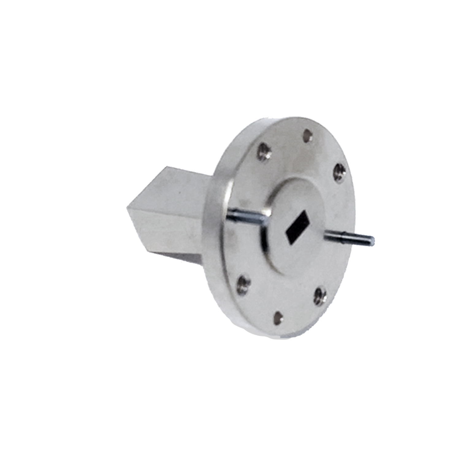
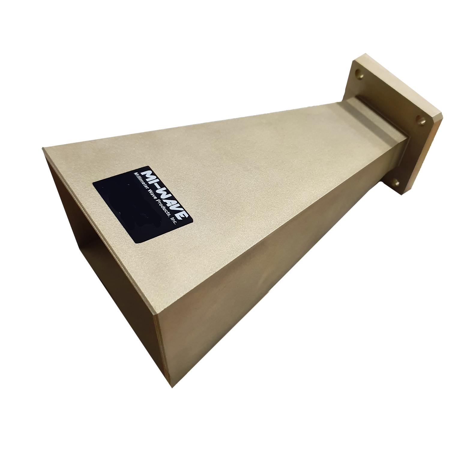
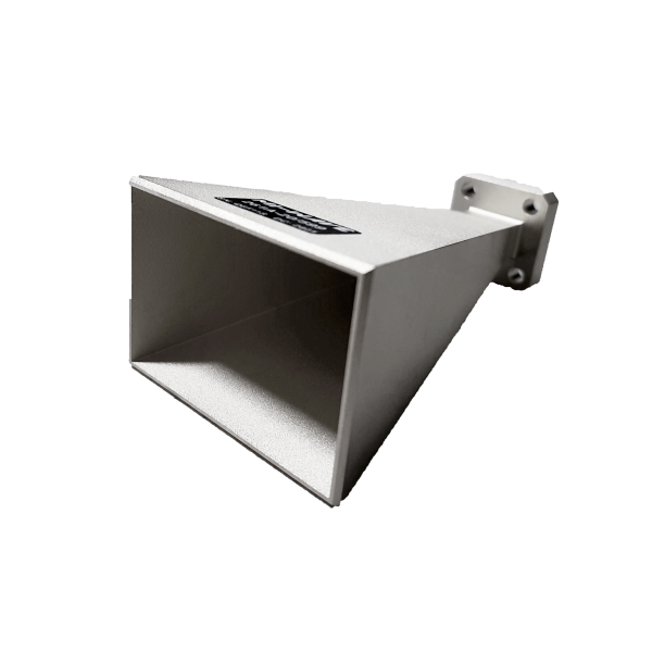
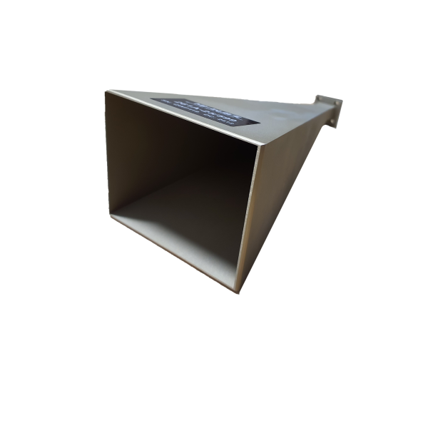
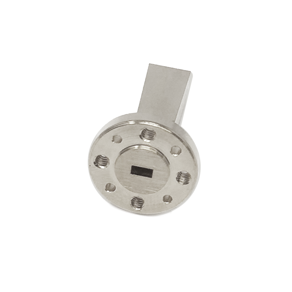
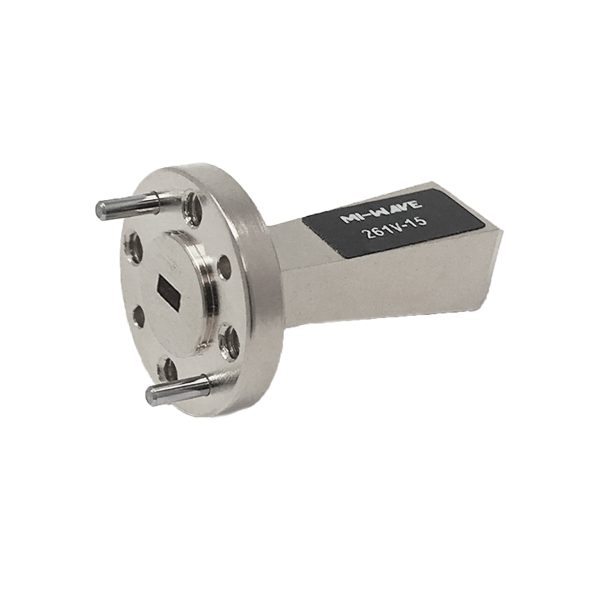
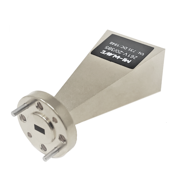
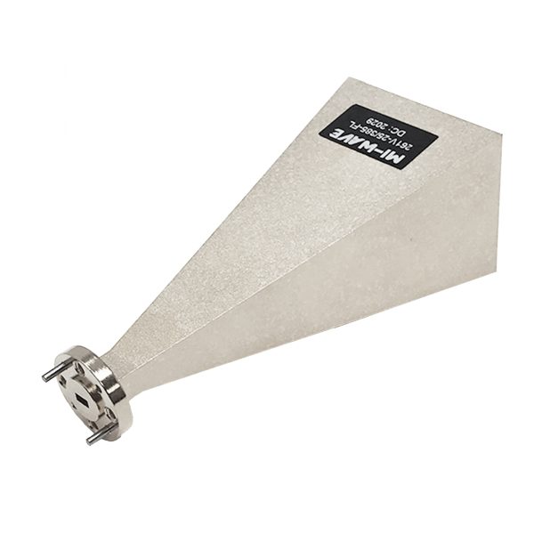
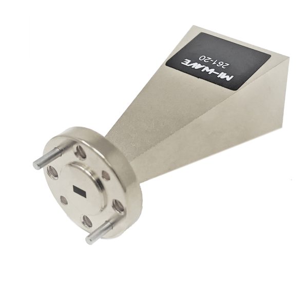
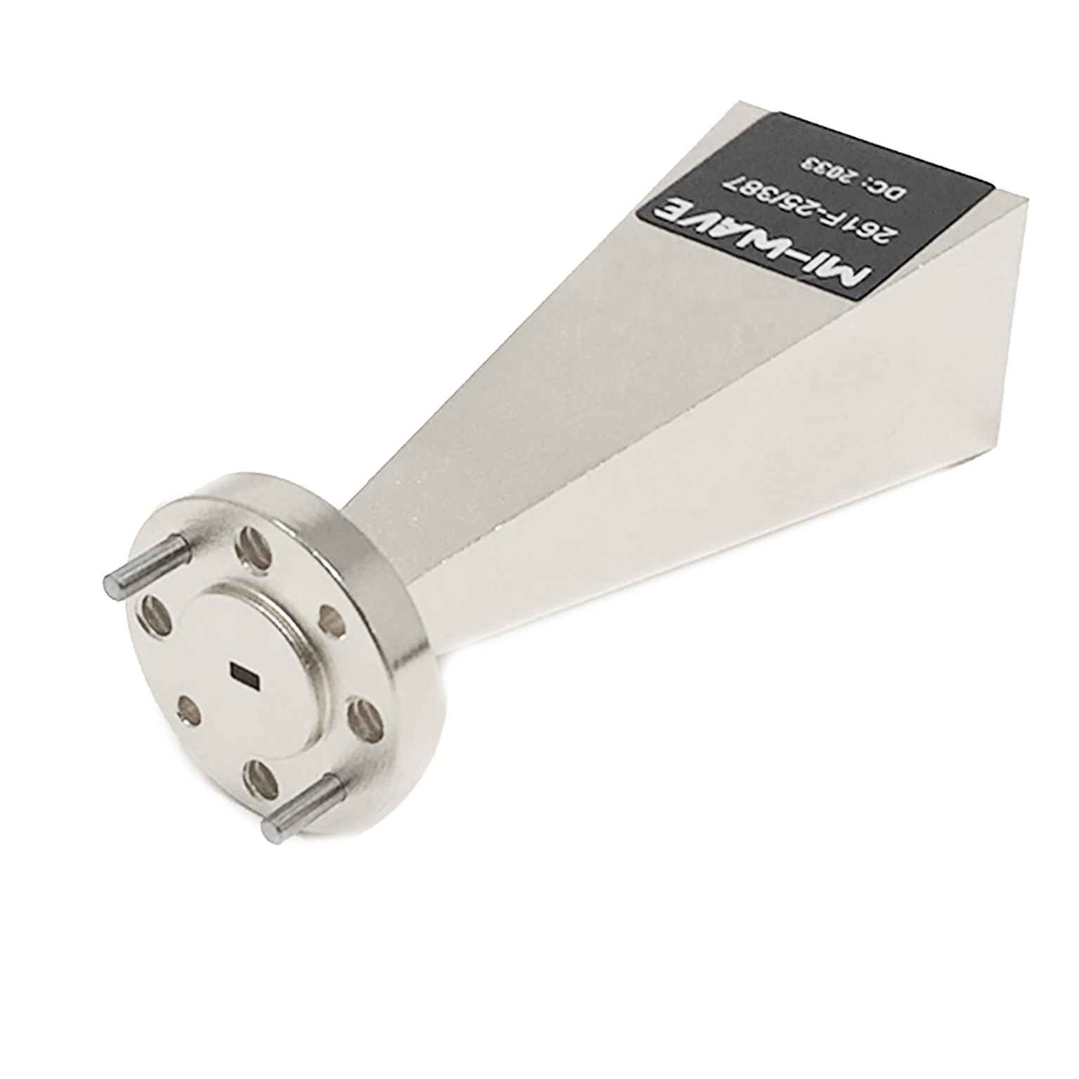
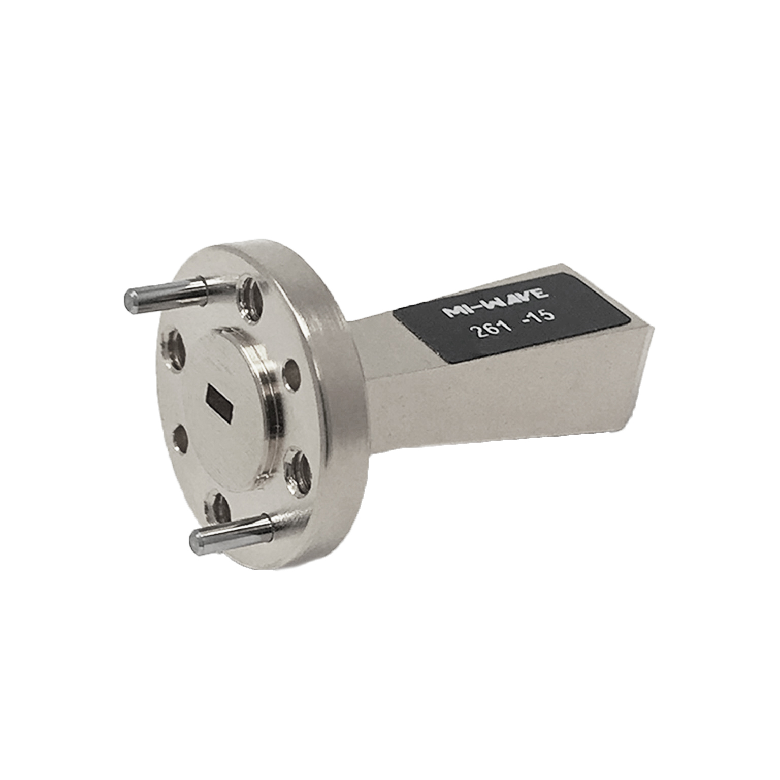
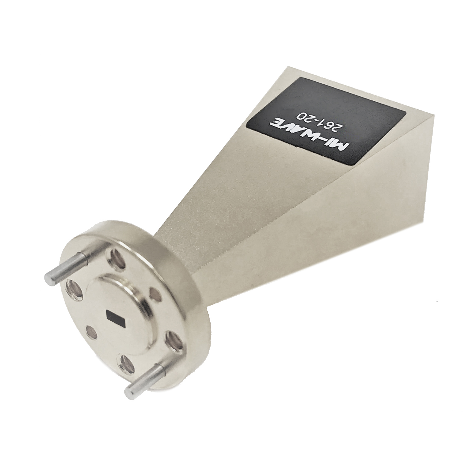
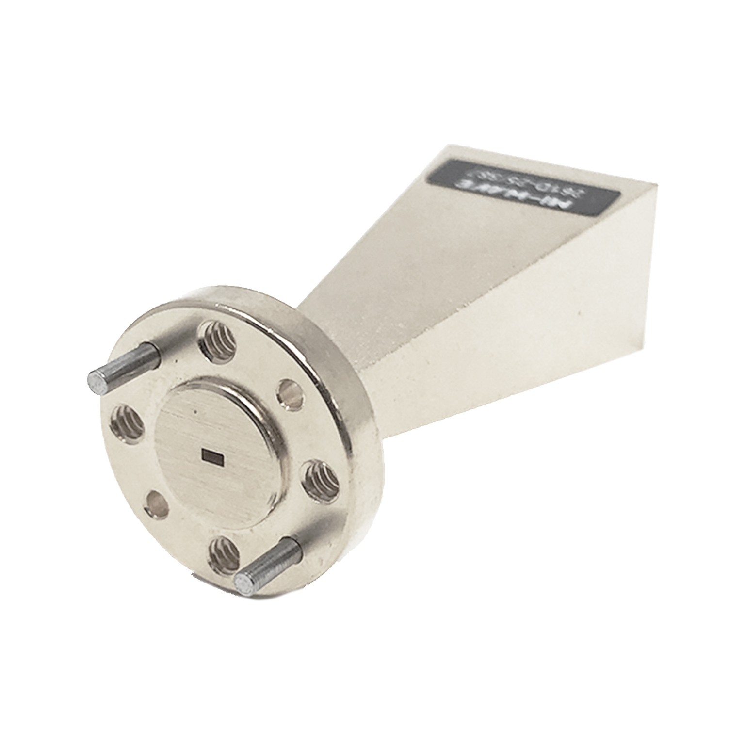
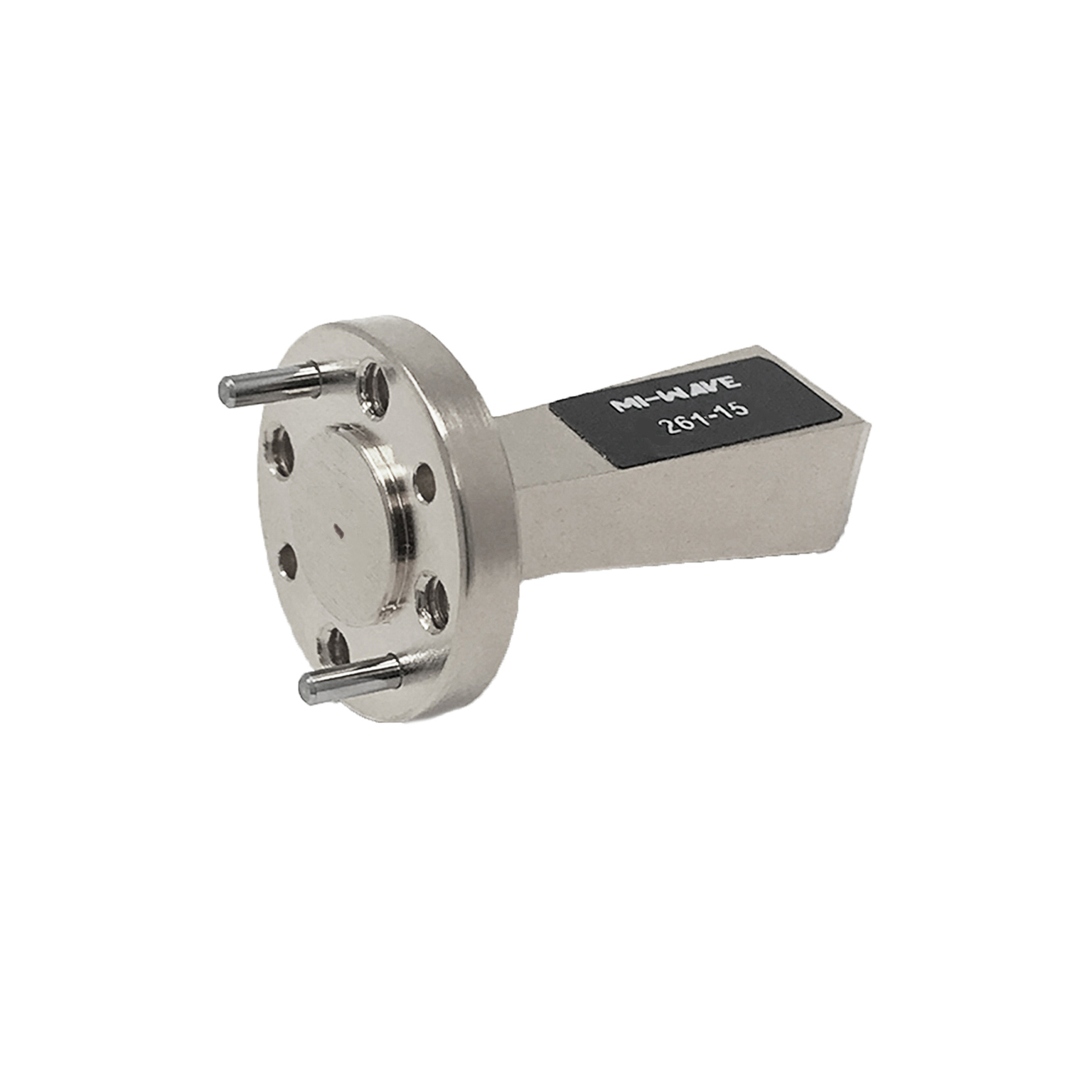
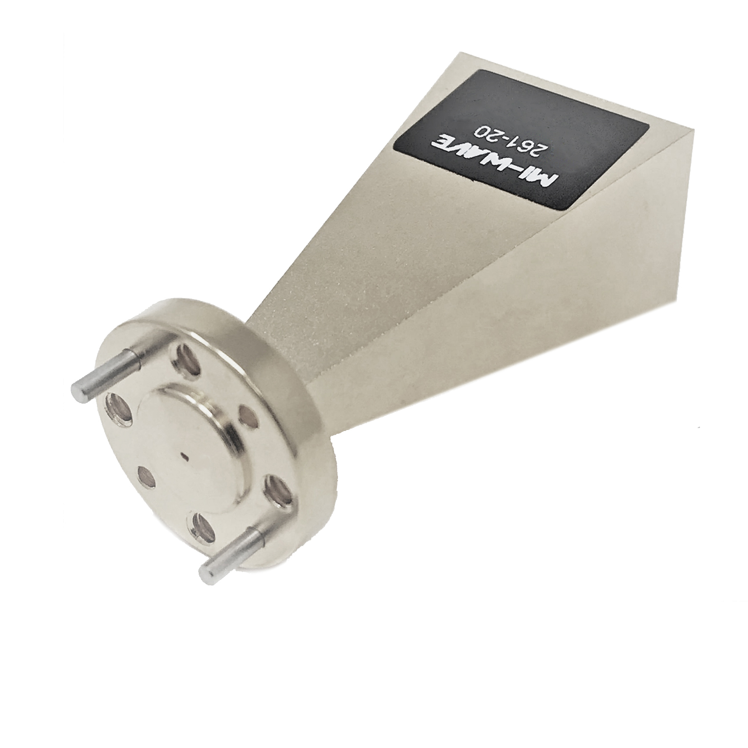
Mi-Wave’s Standard Gain Horn Antennas, including the Series 261, are precision-engineered antennas designed to deliver accurate, repeatable gain and predictable radiation patterns across a wide frequency range from 8.2 GHz to 750 GHz.
These antennas are widely used as reference standards in RF, microwave, and millimeter-wave systems where measurement accuracy, calibration integrity, and performance consistency are critical. Their carefully optimized horn geometry produces well-defined beam patterns, stable polarization characteristics, and low VSWR, ensuring reliable and repeatable results across the operating band.
Series 261 standard gain horn antennas are commonly used in antenna calibration, RF system characterization, and high-frequency testing environments, where traceable and consistent gain performance is required. In addition to laboratory applications, they are also used in communications and radar systems that rely on predictable antenna behavior and controlled radiation patterns.
As a core component of Mi-Wave’s antenna portfolio, these antennas support both precision measurement systems and operational RF platforms, delivering dependable performance across microwave and millimeter-wave frequencies.
The models shown represent only a portion of Mi-Wave’s capabilities. Custom configurations are available to support specific frequency bands, waveguide interfaces, polarization options, and mechanical requirements, ensuring optimized solutions for specialized RF and high-frequency applications.


| Model | Minimum Frequency (GHz) | Maximum Frequency (GHz) | Gain (dBi) typical | Polarization | Beamwidth, E-Plane (db) | Beamwidth, H-Plane (dB) | Side Lobes (E-Plane)(dB) | Side Lobes (H-Plane) (dB) | RF Ports | LINK |
|---|---|---|---|---|---|---|---|---|---|---|
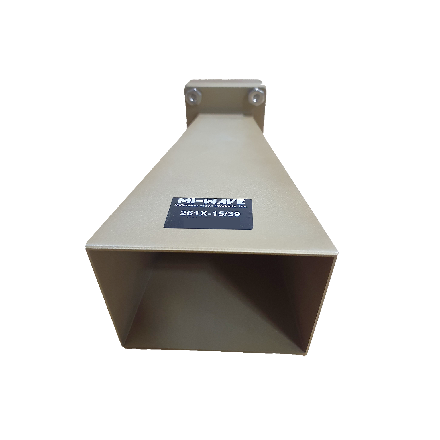
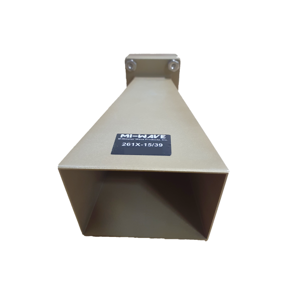
| 261X-15/39 | 8.2 | 12.4 | 15 | Linear | 29.3 | 29 | 20 | 20 | WR-90 Waveguide with UG-39 Flange | |
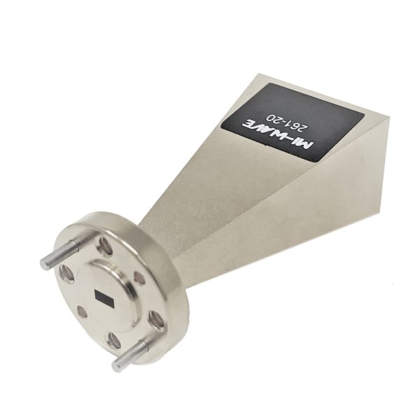
| 261(75)-20/120 | 10 | 15 | 20 | Linear | 16.22 | 19.81 | 12 | 18 | WR-75 waveguide UBR - 120 / U | |
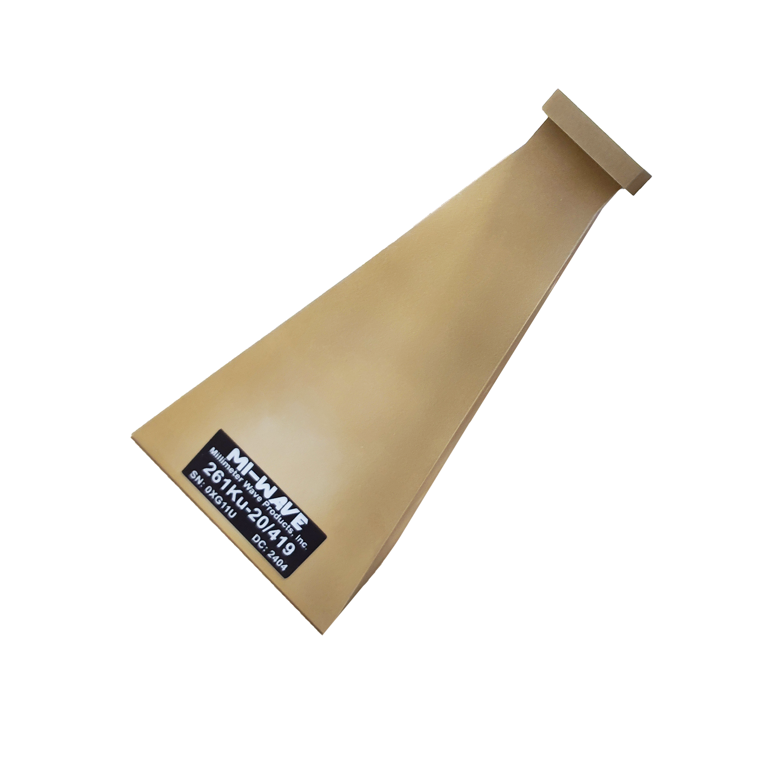
| 261Ku-20/419 | 12 | 18 | 20 | Linear | 16.90 | 17.80 | 16 | 18 | WR-90 Waveguide port UG-419/U Flange | |
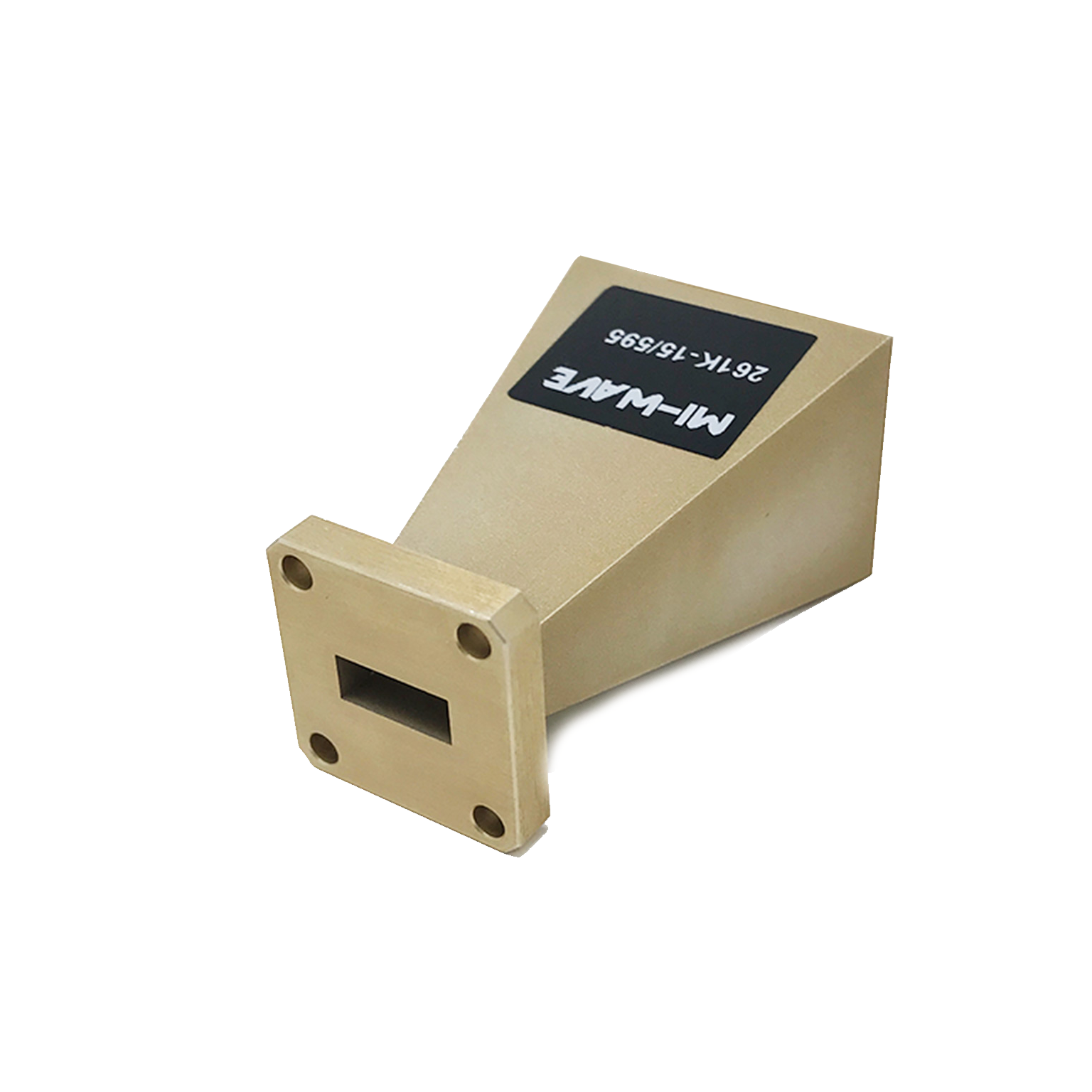
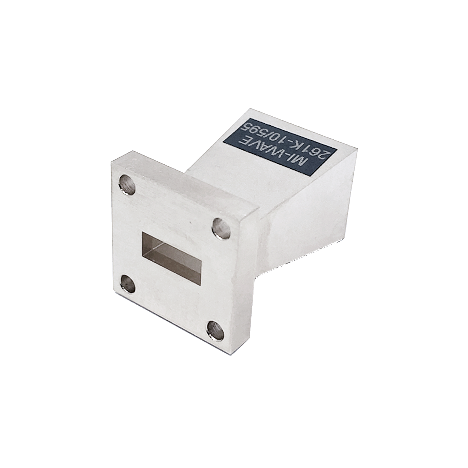
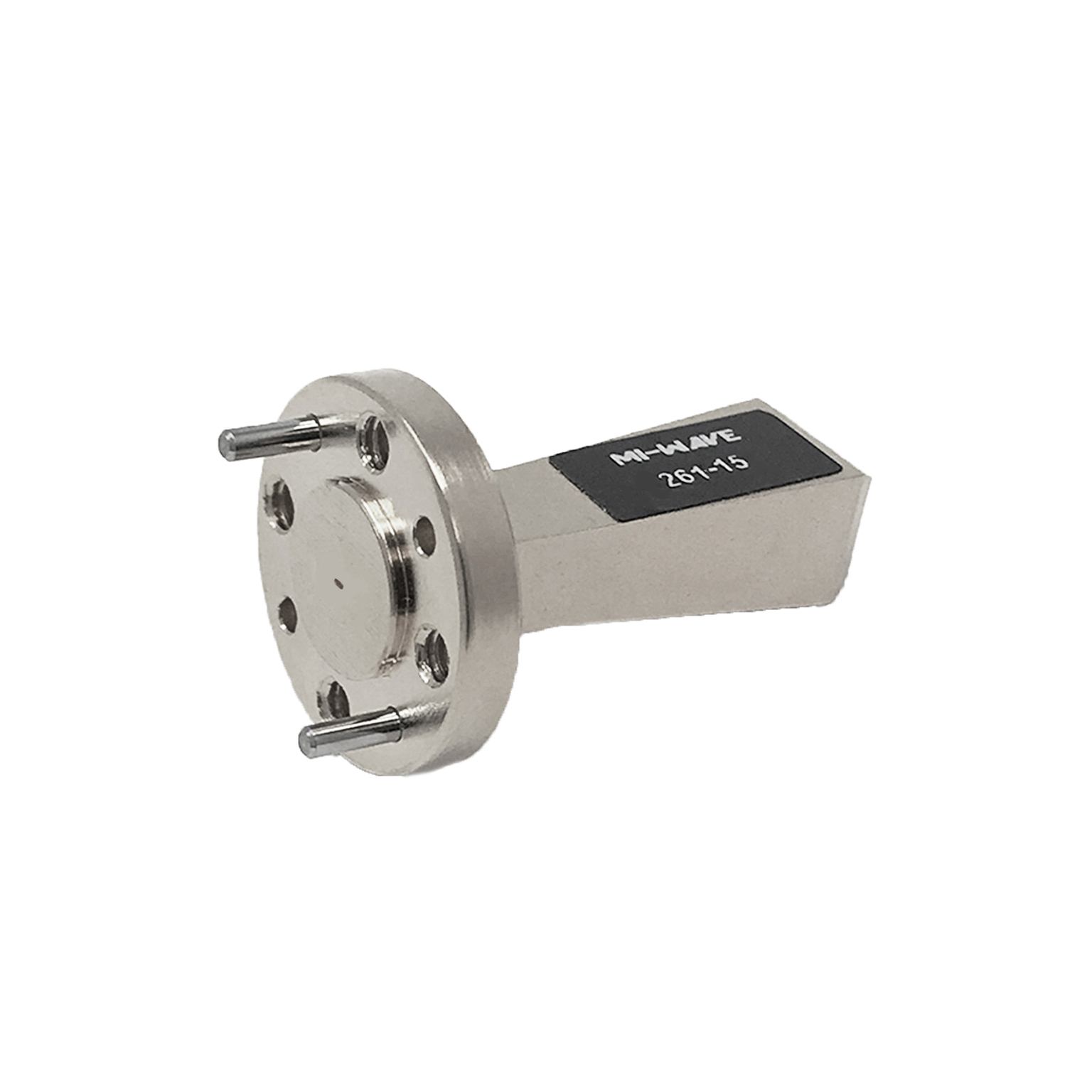
| 261K-10/595 | 18 | 26.5 | 10 | Linear | 55 | 57 | 17 | 25 | WR-42 Waveguide UG-595/U Flange | |
| 261K-15/595 | 18 | 26.5 | 15 | Linear | 19 | 21 | 20 | 23 | WR-42 Waveguide UG-595/U Flange | |
| 261K-20/595 | 18 | 26.5 | 20 | Linear | 19 | 21 | 20 | 20 | WR-42 Waveguide UG-595/U Flange | |
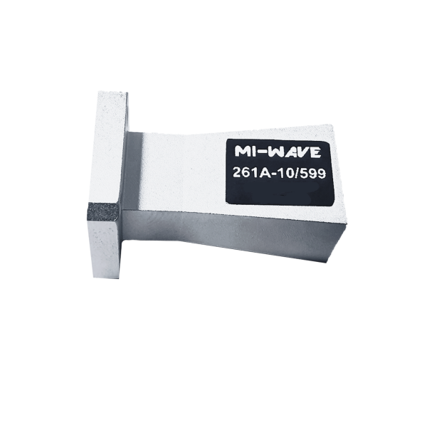
| 261A-10/599 | 26.5 | 40 | 10 | Linear | 56 | 54 | 20 | 20 | WR-28 Waveguide UG-599/U Flange | |
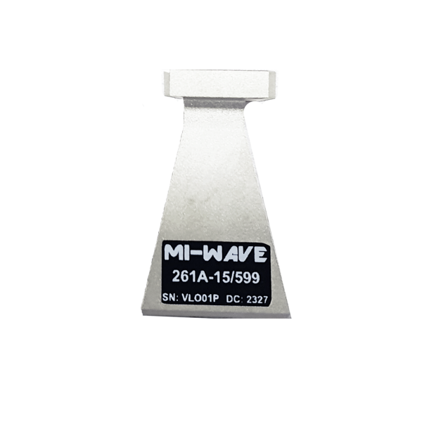
| 261A-15/599 | 26.5 | 40 | 15 | Linear | 33 | 33 | 20 | 20 | WR-28 Waveguide UG-599/U Flange | |
| 261A-20/599 | 26.5 | 40 | 20 | Linear | 16.57 | 16.58 | 20 | 20 | WR-28 Waveguide UG-599/U Flange | |
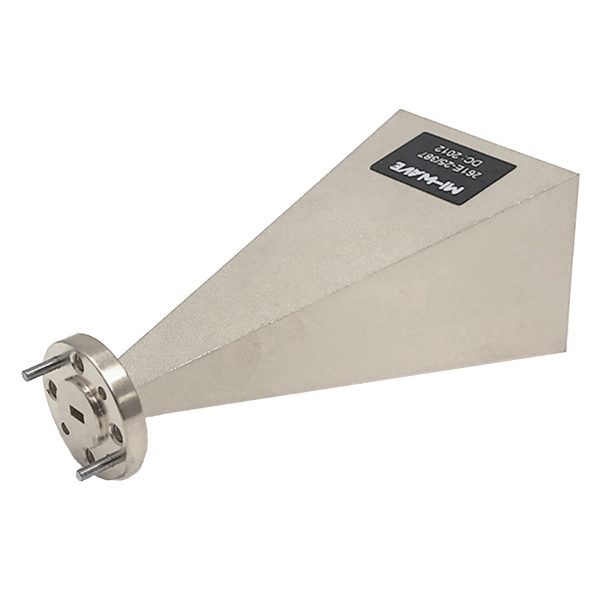
| 261A-25/599 | 26.5 | 40 | 25 | Linear | 7 | 9 | 20 | 20 | WR-28 Waveguide UG-599/U Flange | |
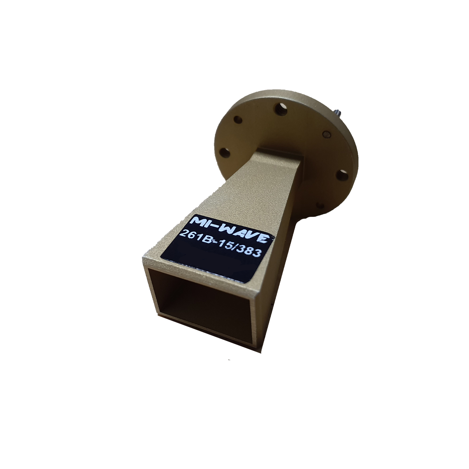
| 261B-15/383 | 33 | 50 | 15 | Linear | 39.81 | 25.9 | 20 | 20 | WR-22 Waveguide UG-383/U Flange | |
| 261B-20/383 | 30 | 50 | 20 | Linear | 15 | 16 | 20 | 20 | WR-22 Waveguide UG-383/U Flange | |
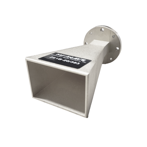
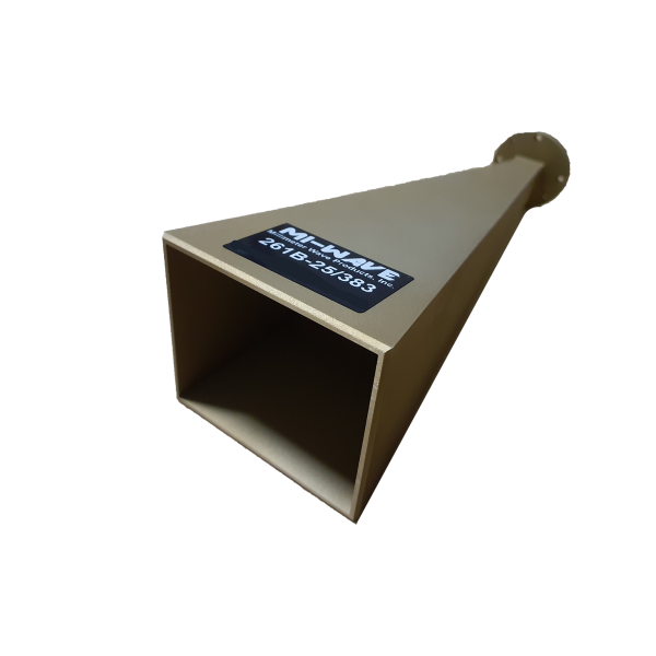
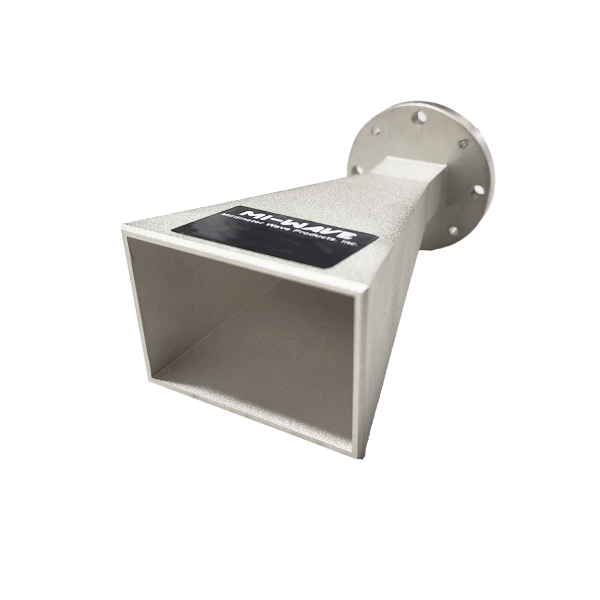
| 261B-25/383 | 33 | 50 | 25 | Linear | 7 | 9 | 20 | 20 | WR-22 Waveguide UG-383/U Flange | |
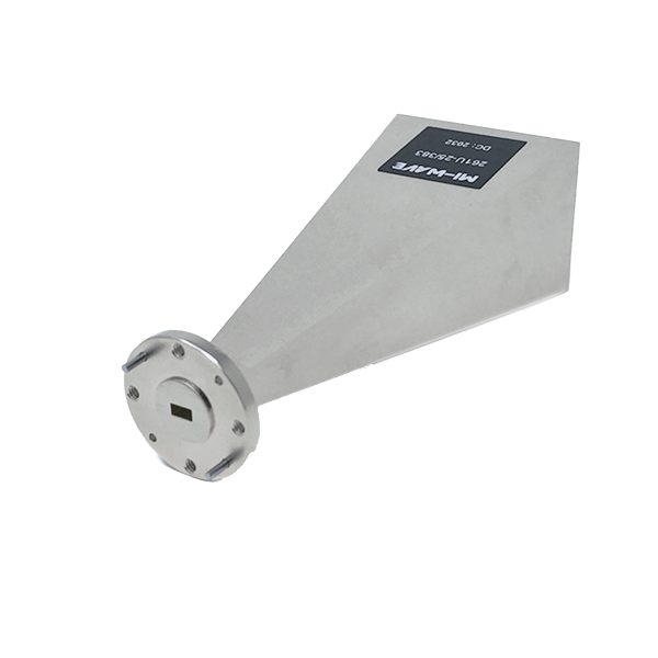
| 261U-10/383 | 40 | 60 | 10 | Linear | 55 | 55 | 20 | 20 | WR-19 Waveguide UG-383/U-M Flange | |
| 261U-15/383 | 40 | 60 | 15 | Linear | 32 | 32 | 14 | 20 | WR-19 Waveguide UG-383/U-M Flange | |
| 261U-20/383 | 40 | 60 | 20 | Linear | 14 | 16 | 14 | 30 | WR-19 Waveguide UG-383/U-M Flange | |
| 261U-25/383 | 40 | 60 | 25 | Linear | 9 | 10 | 20 | 20 | WR-19 Waveguide UG-383/U-M Flange | |
| 261V-10/385 | 50 | 75 | 10 | Linear | 55 | 55 | 20 | 20 | WR-15 Waveguide UG-385/U-M Flange | |
| 261V-15/385 | 50 | 75 | 15 | Linear | 29 | 32 | 20 | 20 | WR-15 Waveguide UG-385/U-M Flange | |
| 261V-20/385 | 50 | 75 | 20 | Linear | 14 | 15 | 20 | 20 | WR-15 Waveguide UG-385/U Flange | |
| 261V-25/385-FL | 50 | 75 | 25 | Linear | 9 | 10 | 20 | 20 | WR-15 Waveguide UG-385/U Flange | |
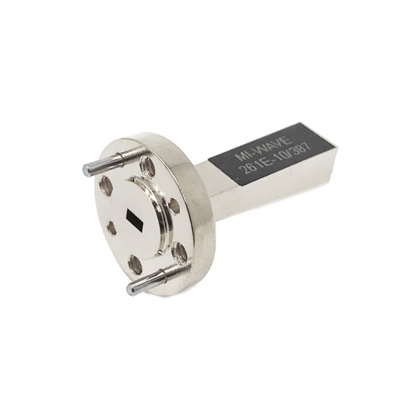
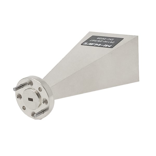
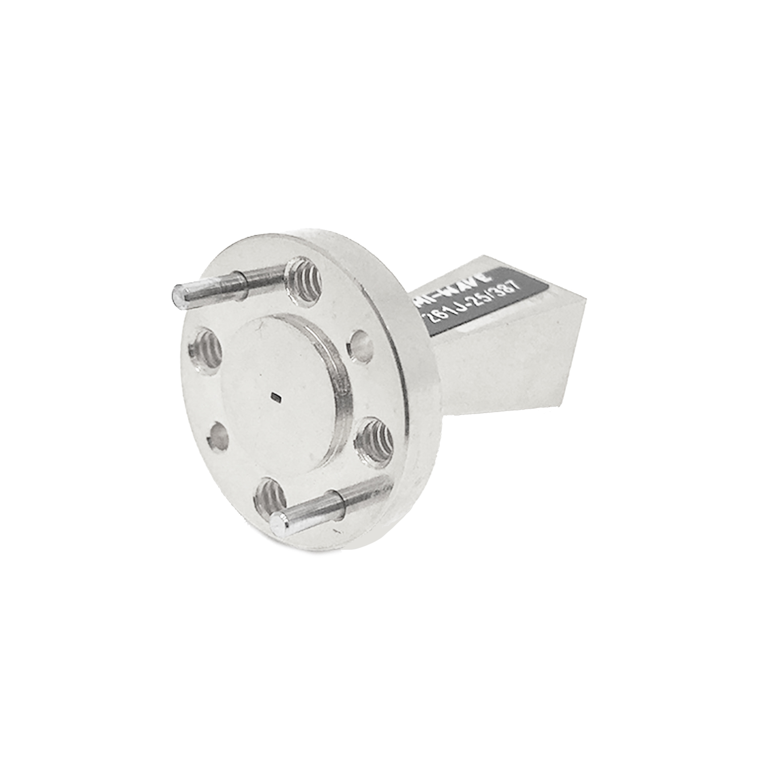
| 261E-10/387 | 60 | 90 | 10 | Linear | 55 | 55 | 20 | 20 | WR-12 Waveguide UG-387/U Flange | |
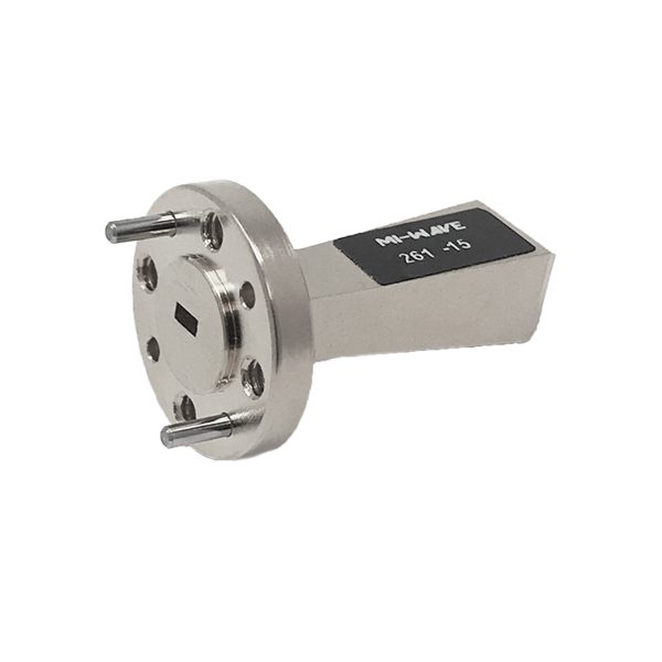
| 261E-15/387 | 60 | 90 | 15 | Linear | 30 | 32 | 20 | 20 | WR-12 Waveguide UG-387/U Flange | |
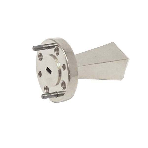
| 261E-20/387 | 60 | 90 | 20 | Linear | 14 | 15 | 20 | 20 | WR-12 Waveguide UG-387/U Flange | |
| 261E-25/387 | 60 | 90 | 25 | Linear | 9 | 10 | 20 | 20 | WR-12 Waveguide UG-387/U Flange | |
| 261W-10/387 | 75 | 110 | 10 | Linear | 51.76 | 52 | 2 | 25 | WR-10 Waveguide UG-387/U-M Flange | |
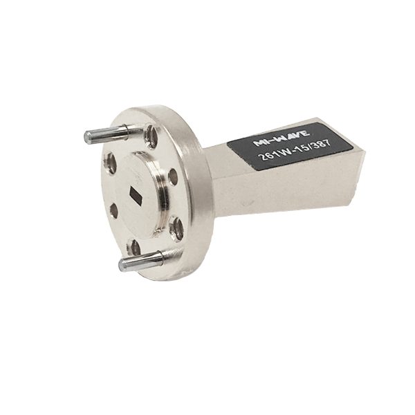
| 261W-15/387 | 75 | 110 | 15 | Linear | 32 | 32 | 14 | 25 | WR-10 Waveguide UG-387/U-M Flange | |
| 261W-20/387 | 75 | 110 | 20 | Linear | 16 | 18 | 20 | 20 | WR-10 Waveguide UG-387/U-M Flange | |
| 261W-25/387-FL | 75 | 110 | 25 | Linear | 9 | 10 | 20 | 20 | WR-10 Waveguide UG-387/U-M Flange | |
| 261F-10/387 | 90 | 140 | 10 | Linear | 53 | 55 | 19 | 22 | WR-08 Waveguide UG-387/U-M Flange | |
| 261F-15/387 | 90 | 140 | 15 | Linear | 29.73 | 33.67 | 14 | 25 | WR-08 Waveguide UG-387/U-M Flange | |
| 261F-20/387 | 90 | 140 | 20 | Linear | 16 | 18 | 14 | 30 | WR-08 Waveguide UG-387/U-M Flange | |
| 261F-25/387 | 90 | 140 | 25 | Linear | 9 | 10 | 12 | 15 | WR-08 Waveguide UG-387/U-M Flange | |
| 261D-15/387 | 110 | 170 | 15 | Linear | 33 | 31 | 20 | 20 | WR-06 Waveguide UG-387/U-M Flange | |
| 261D-20/387 | 110 | 170 | 20 | Linear | 17 | 18 | 20 | 20 | WR-06 Waveguide UG-387/U-M Flange | |
| 261D-25/387 | 110 | 170 | 25 | Linear | 25 | 25.5 | 20 | 20 | WR-06 Waveguide UG-387/U-M Flange | |
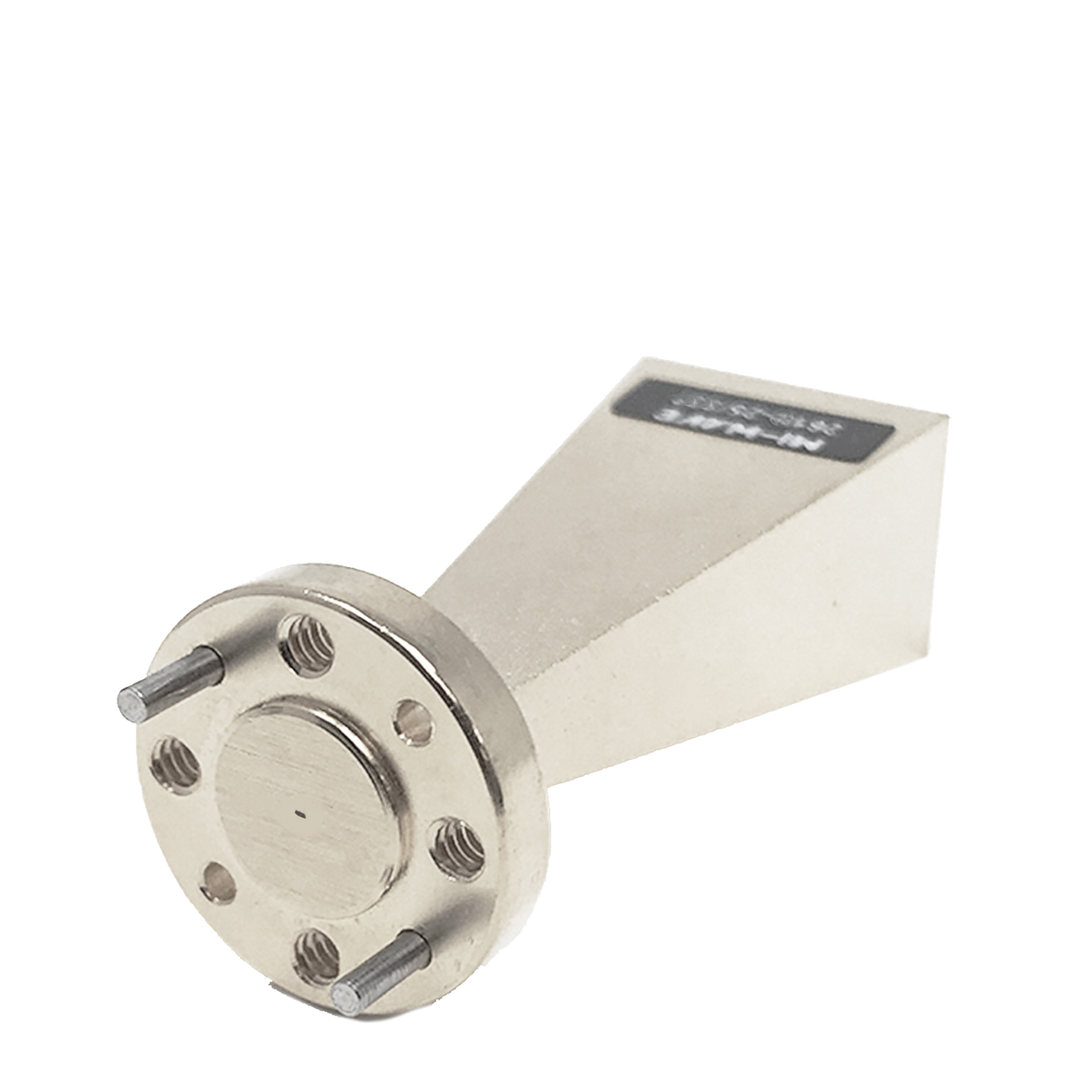
| 261G-10/387 | 140 | 220 | 10 | Linear | 56 | 54 | 19 | 21 | WR-05 Waveguide UG-387/U-M Flange | |
| 261G-15/387 | 140 | 220 | 15 | Linear | 33.41 | 31.9 | 17 | 23 | WR-05 Waveguide UG-387/U-M Flange | |
| 261G-20/387 | 140 | 220 | 20 | Linear | 13 | 13 | 12 | 25 | WR-05 Waveguide UG-387/U-M Flange | |
| 261G-25/387 | 140 | 220 | 25 | Linear | 8.9 | 10.28 | 20 | 20 | WR-05 Waveguide UG-387/U-M Flange | |
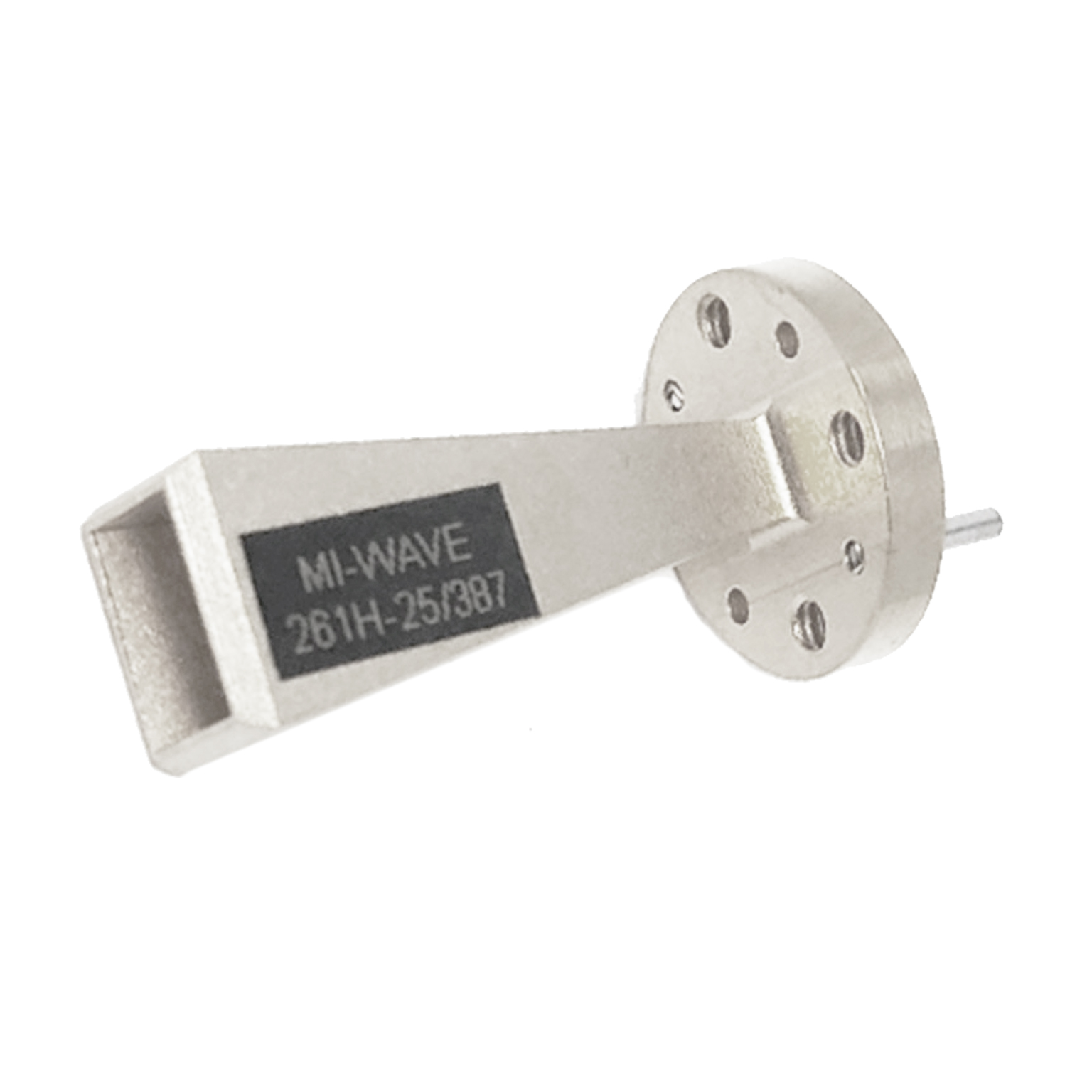
| 261H-25/387 | 170 | 260 | 25 | Linear | 10 | 10 | WR-04 Waveguide UG-387/U Flange | |||
| 261J-15/387 | 220 | 325 | 15 | Linear | 35 | 38 | 14 | 17 | WR-3 Waveguide UG-387/U-M Flange | |
| 261J-25/387 | 220 | 325 | 25 | Linear | 9 | 10 | 20 | 20 | WR-3 Waveguide UG-387/U-M Flange | |
| 261(2.8)-25/387 | 260 | 400 | 25 | Linear | 26.18 | 25.8 | 20 | 20 | WR-2.8 Waveguide UG-387/U-M Flange | |
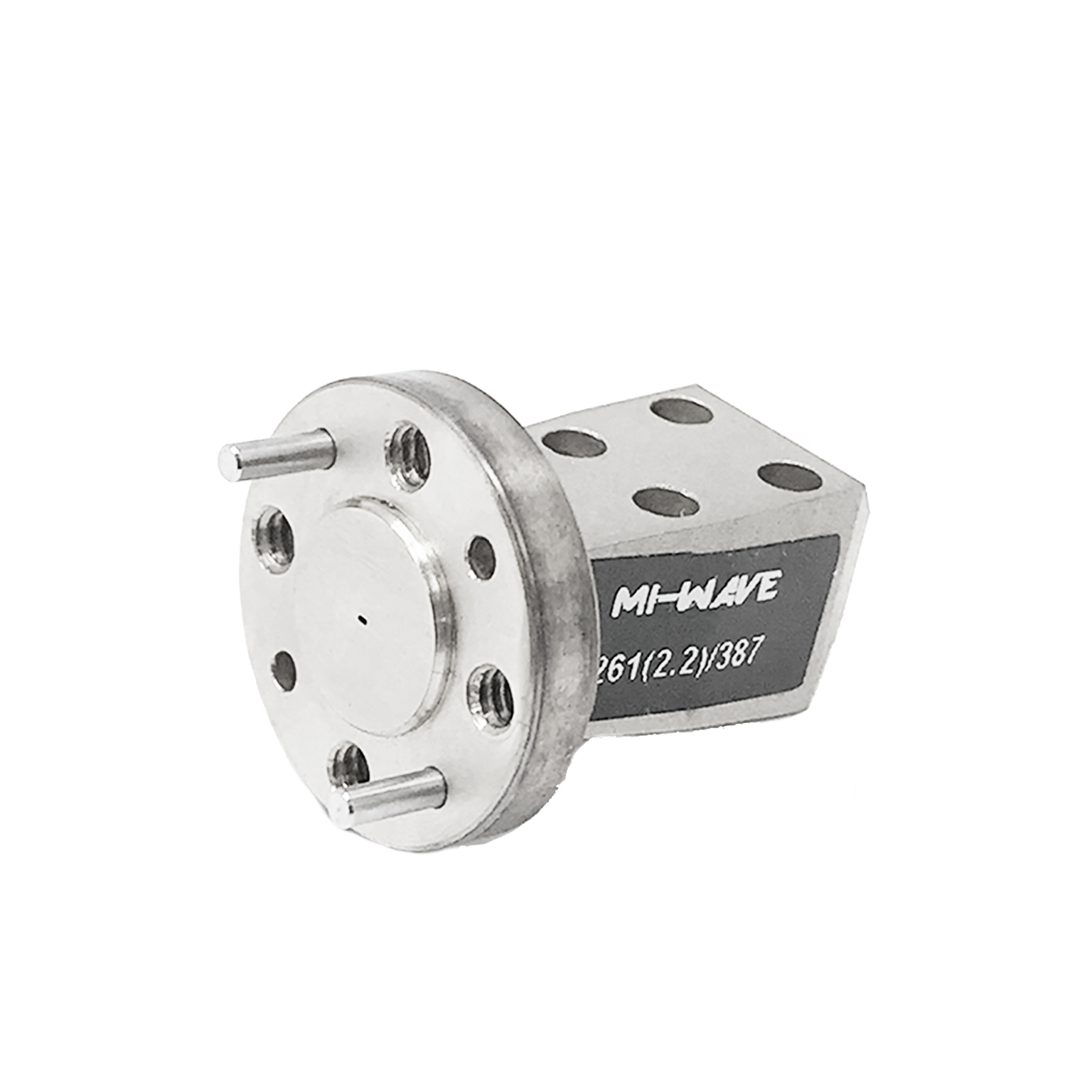
| 261(2.2)/387 | 325 | 500 | 25 | Linear | 13 | 15 | 22 | 23 | WR-2.2 Waveguide UG-387/U-M Flange | |
| 261(1.5)-25/387 | 500 | 750 | 25 | Linear | 22 | 23 | WR-1.5 Waveguide UG-387/U-M Flange |
*All data presented is collected from a sample lot.
* Actual data may vary unit to unit, slightly.
*All testing was performed under +25 °C case temperature.
*Consult factory to confirm if material, plating, size, shape, orientation and any electrical parameter is critical for the application as website information is for reference only.
*Millimeter Wave Products, Inc. reserves the right to change the information presented on website without notice as we continue to enhance the performance and design of our products.
Key Features & Performance Benefits
Accurate and Repeatable Gain
Standard gain horn antennas are designed to provide precisely known gain values, making them ideal as reference antennas for calibration and measurement systems.
Ultra-Wide Frequency Coverage (8.2–750 GHz)
Supports an extensive range of microwave, millimeter-wave, and submillimeter frequencies, enabling use across a wide variety of RF applications.
Predictable Radiation Patterns
Optimized horn geometry produces well-defined and stable beam patterns, allowing engineers to rely on consistent antenna performance.
Low VSWR and Excellent Impedance Matching
Designed to minimize reflections and ensure efficient power transfer, improving measurement accuracy and system performance.
Stable Polarization Characteristics
Maintains consistent polarization behavior across frequency, which is critical for calibration and high-precision RF systems.
High Directivity
Provides strong directional performance, improving signal clarity and reducing unwanted radiation.
Ideal for Calibration and Reference Use
Widely used as standard reference antennas in antenna measurement ranges, test labs, and verification systems.
Broad Waveguide Compatibility
Available with standard waveguide interfaces, allowing seamless integration into existing RF systems.
Robust Mechanical Construction
Built for durability and repeatability in both laboratory and field environments.
Custom Configurations Available
Supports custom frequency ranges, waveguide sizes, polarization types, and mechanical designs to meet specialized requirements.
Applications
Mi-Wave Standard Gain Horn Antennas are widely used in RF, microwave, and millimeter-wave systems that require accurate gain reference, predictable radiation patterns, and repeatable performance across wide frequency ranges.
These antennas are essential in environments where measurement accuracy, calibration traceability, and system verification are critical, making them a foundational tool in both laboratory and operational RF systems.
Antenna Calibration and Measurement
Standard gain horn antennas are most commonly used as reference antennas in antenna measurement systems due to their known gain characteristics and stable radiation patterns.
Typical applications include:
- Antenna gain calibration and validation
- Reference antenna measurements in test ranges
- Near-field and far-field antenna testing
- Radiation pattern characterization
- Verification of antenna beamwidth and sidelobe levels
- Calibration of measurement systems and instrumentation
- Standard reference use in accredited test facilities
Their traceable and repeatable performance makes them indispensable for ensuring measurement accuracy across RF systems.
RF and Microwave Test Systems
These antennas are widely used in RF testing and validation environments where consistent and predictable antenna behavior is required.
Typical applications include:
- RF system characterization and validation
- Component and subsystem testing
- Signal source verification
- Calibration setups for measurement equipment
- Performance benchmarking of RF devices
- EMC pre-compliance testing setups
- Laboratory-based RF experimentation
Their stable gain and low VSWR enable accurate signal measurement and system verification.
Radar Systems and Radar Testing
Standard gain horn antennas are used in radar systems where controlled radiation patterns and known gain performance are essential.
Common radar applications include:
- Radar cross-section (RCS) testing
- Radar calibration and system verification
- Signal transmission and reception in radar test setups
- FMCW and pulse radar research systems
- High-frequency radar experimentation
- Millimeter-wave radar development
Their predictable performance allows engineers to control signal illumination and improve measurement precision.
Communications Systems
These antennas are used in communication systems where known gain, stable polarization, and controlled beam patterns are required.
Typical applications include:
- Microwave and millimeter-wave communication links
- Satellite communication testing and validation
- Ground station calibration
- Signal transmission verification
- Experimental and prototype communication systems
- Link budget validation and RF planning
Their consistent characteristics support reliable system design and performance validation.
RF and Microwave Laboratory Research
Standard gain horn antennas are commonly used in academic, government, and industrial research environments where precise RF measurements are required.
Typical research applications include:
- Microwave and millimeter-wave system development
- RF propagation studies
- Advanced antenna design research
- Component characterization and validation
- Experimental RF system prototyping
- Government and defense research programs
These antennas provide a stable and repeatable RF reference platform for experimental work.
EMC and Compliance Testing
Standard gain horn antennas are also used in electromagnetic compatibility (EMC) testing environments where controlled radiation is required.
Common EMC applications include:
- Radiated emissions testing
- RF susceptibility testing
- Controlled RF illumination in chambers
- Compliance verification and certification testing
- Shielding effectiveness testing
Their predictable radiation patterns help ensure accurate and repeatable EMC measurements.
Frequently Asked Questions (FAQ)
What is a standard gain horn antenna?
A standard gain horn antenna is a precision antenna with a known and repeatable gain, commonly used as a reference in RF measurement and calibration systems.
Why are standard gain horn antennas used as reference antennas?
Because they provide accurate, stable, and predictable gain values, allowing engineers to calibrate and validate other antennas and RF systems.
What frequencies do these antennas support?
Mi-Wave standard gain horn antennas are available from 8.2 GHz to 750 GHz, covering microwave, millimeter-wave, and submillimeter frequencies.
What makes standard gain horns accurate?
Their precise geometry, controlled manufacturing tolerances, and well-characterized performance ensure consistent and repeatable results.
What is VSWR and why is it important?
VSWR measures how well an antenna is matched to a system. Low VSWR reduces reflections and improves measurement accuracy.
Are these antennas used outside of labs?
Yes. While commonly used in measurement systems, they are also used in communications, radar, and field testing applications.
Can standard gain horn antennas be customized?
Yes. Mi-Wave offers custom options for frequency bands, waveguide interfaces, polarization, and mechanical configurations.
What determines the gain of a horn antenna?
Gain is influenced by aperture size, frequency, and antenna efficiency.
What is the difference between standard gain horns and other antennas?
Standard gain horns are specifically designed for accuracy and repeatability, rather than maximum performance alone.
.
Standard Gain Horn Antenna Engineering Calculators
These RF engineering calculators help estimate antenna performance for standard gain horn antennas, including calibration systems, antenna measurement ranges, radar platforms, communications systems, and microwave and millimeter-wave test environments. Use them to calculate antenna gain, beamwidth, aperture size required for target gain, effective aperture, free-space path loss, and wavelength across RF, microwave, millimeter-wave, and submillimeter-wave frequencies.
Standard gain horn antennas are designed for accurate, repeatable gain, predictable radiation patterns, and stable reference performance. A typical starting efficiency range for many systems is 0.50 to 0.75.
Antenna Gain Calculator
Antenna Gain (dBi):
Antenna Beamwidth Calculator
Aperture Size Required for Target Gain
Antenna Effective Aperture Calculator
Effective Aperture (m²):
Free Space Path Loss Calculator
RF Wavelength Calculator
Wavelength (mm):
Glossary of Gain Horn Antenna Terms
This glossary provides detailed definitions of key terms related to gain horn antennas used in RF, microwave, and millimeter-wave systems. These antennas are commonly used in testing, measurement, communications, radar, and high-frequency research applications where precision, repeatability, and wideband performance are critical.
Antenna Fundamentals
Standard Gain Horn Antenna
A precision horn antenna with well-characterized and repeatable gain, used as a reference standard in RF and microwave measurement systems.
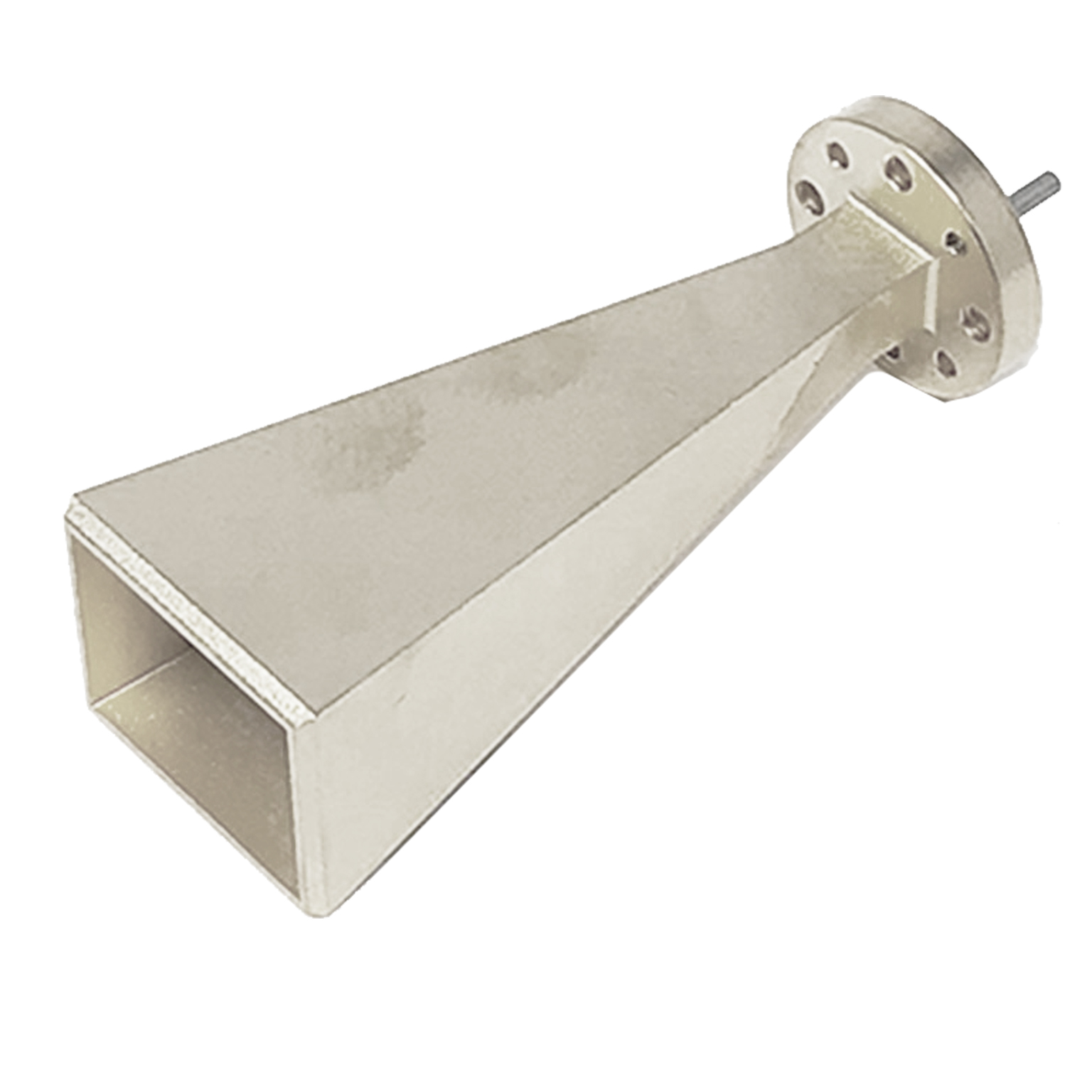
Horn Antenna
A flared waveguide structure that transitions guided waves into free space with controlled directivity and low loss.
Reference Antenna
An antenna with known performance used to calibrate measurement systems and validate other antennas.
Antenna Aperture
The physical opening through which RF energy is radiated. Larger apertures generally result in higher gain.
Radiation Pattern
A graphical representation of how an antenna radiates energy in space.
Main Lobe
The primary direction of radiation where most energy is concentrated.
Sidelobes
Secondary radiation peaks outside the main beam that can introduce interference.
Back Lobe
Radiation emitted opposite the main direction.
Electrical Performance Terms
Gain (dBi)
A logarithmic measure of how effectively an antenna directs RF energy compared to an isotropic source.
Directivity
The degree to which an antenna focuses energy in a specific direction.
VSWR (Voltage Standing Wave Ratio)
A measure of impedance matching. Lower VSWR indicates better power transfer and less reflection.
Return Loss (dB)
The amount of reflected signal power caused by impedance mismatch.
Impedance Matching
Ensuring maximum power transfer between RF components by minimizing reflections.
Polarization
The orientation of the electric field of the RF signal, typically linear or circular.
Gain Accuracy
The precision with which an antenna’s gain is known, critical for calibration applications.
Gain Stability
The consistency of gain across frequency, temperature, and environmental conditions.
Measurement and Calibration Terms
Calibration
The process of verifying system performance using a known reference standard.
Traceability
The ability to relate measurements to recognized standards through an unbroken chain of comparisons.
Reference Measurement
A measurement made using a known standard for comparison.
Near-Field Measurement
Measurement performed close to the antenna, requiring transformation to far-field data.
Far-Field Measurement
Measurement taken at a distance where the radiation pattern is fully developed.
Antenna Range
A controlled environment used for antenna testing and measurement.
Measurement Uncertainty
The degree of confidence in a measurement result.
RF and Frequency Terms
Radio Frequency (RF)
Electromagnetic frequencies used for communication, radar, and sensing.
Microwave (1–30 GHz)
Frequency range used in many communication and radar systems.
Millimeter-Wave (30–300 GHz)
High-frequency range used in advanced communications and radar systems.
Submillimeter-Wave (300–750 GHz)
Very high frequencies used in research and specialized applications.
Bandwidth
The range of frequencies over which an antenna operates effectively.
Wavelength (λ)
The physical length of one cycle of an electromagnetic wave.
Waveguide and Mechanical Terms
Waveguide
A structure that guides RF energy, commonly used at microwave and mmWave frequencies.
Waveguide Flange
A standardized connection method for joining waveguide components.
WR Designation
Standardized waveguide sizes (e.g., WR-90, WR-10) corresponding to frequency bands.
Aperture Size
The physical dimension of the horn opening, affecting gain and beamwidth.
Mechanical Tolerance
The allowable variation in manufacturing dimensions.
Precision Machining
High-accuracy fabrication required for high-frequency RF components.
Performance and Efficiency
Aperture Efficiency (η)
The ratio of effective radiating area to physical aperture.
Effective Aperture (Ae)
The portion of the antenna that effectively captures or transmits energy.
Ohmic Loss
Loss due to resistance in conductive materials.
Surface Roughness Effects
At high frequencies, surface imperfections increase RF losses.
Thermal Stability
The ability to maintain performance across temperature changes.
Applications and Systems
Test and Measurement Systems
Systems used to evaluate RF performance.
Radar Systems
Systems using RF for detection and tracking.
Communications Systems
Systems transmitting and receiving RF signals.
EMC Testing
Testing for electromagnetic compatibility and interference.
Research and Development (R&D)
Experimental and developmental RF work.
Frequency Bands
- X-Band: 8–12 GHz
- Ku-Band: 12–18 GHz
- Ka-Band: 26–40 GHz
- Q-Band: 33–50 GHz
- V-Band: 50–75 GHz
- W-Band: 75–110 GHz
- D-Band: 110–170 GHz
- Submillimeter Range: 170–750 GHz


Why Choose Mi-Wave
Mi-Wave is a trusted manufacturer of RF, microwave, and millimeter-wave antennas and components, supporting commercial, government, and research systems worldwide. Our Series 261 standard gain horn antennas are engineered to deliver measurement-grade accuracy, stable radiation patterns, and reliable electrical performance in demanding high-frequency environments.
High-Frequency Engineering Expertise
With decades of experience in microwave and millimeter-wave design, Mi-Wave develops standard gain horn antennas optimized for accurate gain values, low VSWR, and controlled beamwidths across broad operating bandwidths.
Precision Manufacturing and Quality Control
Each antenna is manufactured using precision machining and controlled assembly processes to ensure repeatable electrical performance, mechanical stability, and long-term reliability, which are essential for calibration and reference applications.
Broad Frequency and Application Support
Mi-Wave supports standard gain horn antennas across a wide range of RF, microwave, and millimeter-wave frequency bands, making them suitable for antenna calibration, communications, radar, telemetry, and test environments.
Custom Antenna Solutions
In addition to standard offerings, Mi-Wave provides custom standard gain horn antenna designs tailored to specific frequency ranges, gain requirements, polarization options, waveguide interfaces, and mechanical constraints. Our sales engineering team works closely with customers to ensure seamless system integration.
What Standard Gain Horn Antennas Are and What They Do
Standard gain horn antennas are directional horn antennas designed to provide known, predictable gain values and stable radiation patterns over a specified frequency range. They are commonly used as reference standards in antenna measurements and system calibration.
Unlike broadband horns optimized primarily for coverage, standard gain horns are designed with controlled geometry and known electrical characteristics, allowing engineers to accurately measure antenna gain, verify system performance, and establish traceable calibration references.
How Standard Gain Horn Antennas Work
RF energy enters the antenna through a standard waveguide interface and propagates toward the horn aperture. As the signal travels through the horn flare, the electromagnetic fields are shaped to produce a well-defined main beam with controlled sidelobes and predictable polarization behavior.
This design provides:
-
Accurate and repeatable gain values
-
Stable beamwidth and radiation patterns
-
Low VSWR and minimal signal reflections
-
Consistent polarization characteristics
These attributes are essential for antenna calibration, pattern measurement, and system verification.
Frequency Coverage and Waveguide Interfaces
Mi-Wave Series 261 standard gain horn antennas support operation across a wide range of RF, microwave, and millimeter-wave frequencies, depending on configuration. Typical coverage spans from X-Band through W-Band, with custom frequency ranges available.
Common supported WR waveguide interfaces include:
-
WR-90 | X-Band
-
WR-62 | Ku-Band
-
WR-42 | K-Band
-
WR-28 | Ka-Band
-
WR-22 | Q-Band
-
WR-15 | V-Band
-
WR-10 | W-Band
Additional waveguide sizes and frequency extensions are available upon request.
Why Standard Gain Horns Matter
Standard gain horn antennas play a critical role in high-frequency systems because they provide a reliable reference for performance measurement and validation. Their known gain and stable radiation patterns allow engineers to:
-
Accurately measure and compare antenna performance
-
Calibrate test ranges and measurement equipment
-
Validate RF, microwave, and millimeter-wave systems
-
Ensure repeatability and traceability in test results
These capabilities are essential in communications, radar, telemetry, and research environments where measurement accuracy directly impacts system performance.
Features
-
Known, calibrated gain characteristics
Designed to provide accurate and repeatable gain values, making Series 261 horns ideal as reference antennas for measurement and calibration applications. -
Stable and predictable radiation patterns
Produces well-defined main beams with controlled sidelobes, ensuring consistent and repeatable performance across the operating frequency band. -
Low VSWR across the operating band
Ensures efficient power transfer, minimal signal reflection, and improved measurement accuracy in high-frequency RF systems. -
Controlled beamwidth and sidelobe performance
Optimized horn geometry provides reliable beam shape and directivity, supporting precise antenna characterization and system verification. -
Stable polarization characteristics
Maintains consistent polarization behavior across frequency, supporting accurate polarization measurements and system alignment. -
Wideband frequency support within defined bands
Each standard gain horn is designed to operate predictably across its designated RF, microwave, or millimeter-wave band. -
High power handling capability
Suitable for both transmit and receive applications, including demanding test and validation environments. -
Precision mechanical construction
Manufactured with tight tolerances to ensure mechanical stability, repeatability, and long-term reliability. -
Compatibility with standard WR waveguide interfaces
Allows easy integration into existing RF, microwave, and millimeter-wave signal chains. -
Laboratory and field-ready design
Suitable for use in controlled lab environments as well as portable or field-deployed test setups. -
Custom configurations available
Optional customization for frequency range, waveguide interface, polarization, and mechanical mounting requirements.
Applications
-
Antenna Calibration and Gain Measurements
Widely used as reference antennas for determining absolute gain and verifying antenna performance in calibrated test ranges. -
RF, Microwave, and Millimeter-Wave Test & Measurement
Supports system characterization, component testing, and validation across high-frequency bands. -
Antenna Pattern and Polarization Characterization
Used to measure radiation patterns, beamwidth, sidelobe levels, and polarization purity of antennas under test. -
System Calibration and Verification
Enables repeatable calibration of RF systems, test equipment, and measurement setups. -
Radar and Telemetry Systems
Suitable for radar and telemetry applications requiring predictable beam characteristics and stable gain. -
Point-to-Point Communication Systems
Used in line-of-sight communication links where controlled directivity and known gain are required. -
EMC, EMI, and RCS Measurement Environments
Supports electromagnetic compatibility testing and radar cross-section measurements where repeatable antenna performance is critical. -
Research and Development Platforms
Ideal for R&D environments requiring reliable reference antennas for experimentation and system evaluation. -
Production Test and Quality Assurance
Used in manufacturing and QA environments to verify antenna and system performance before deployment.