
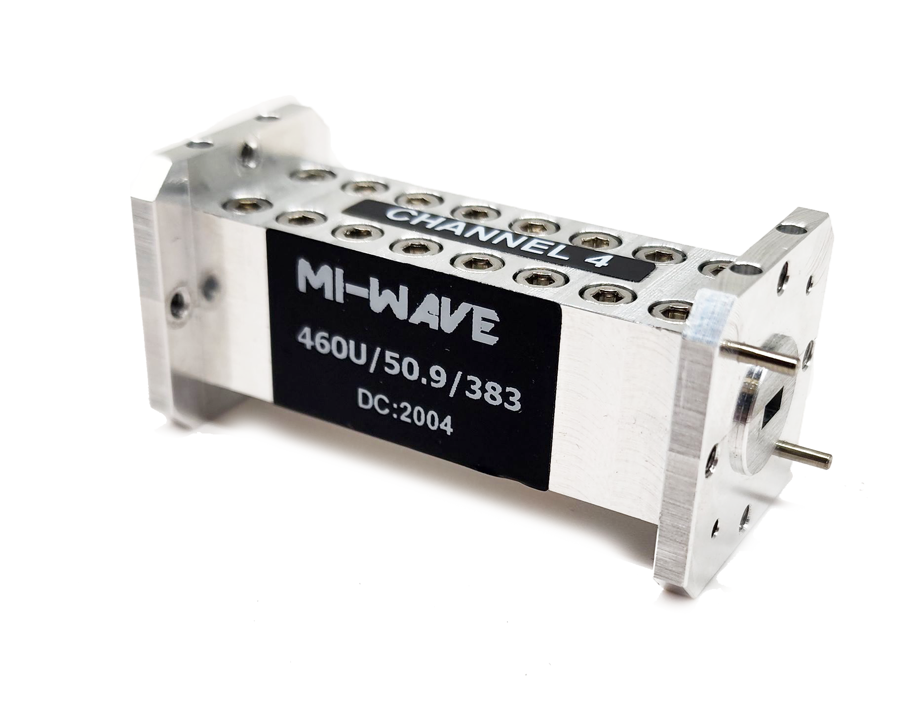
Mi-Wave 460 Series — Waveguide Bandpass Filter Specifications
Precision RF, Microwave, and Millimeter-Wave Bandpass Filtering Solutions
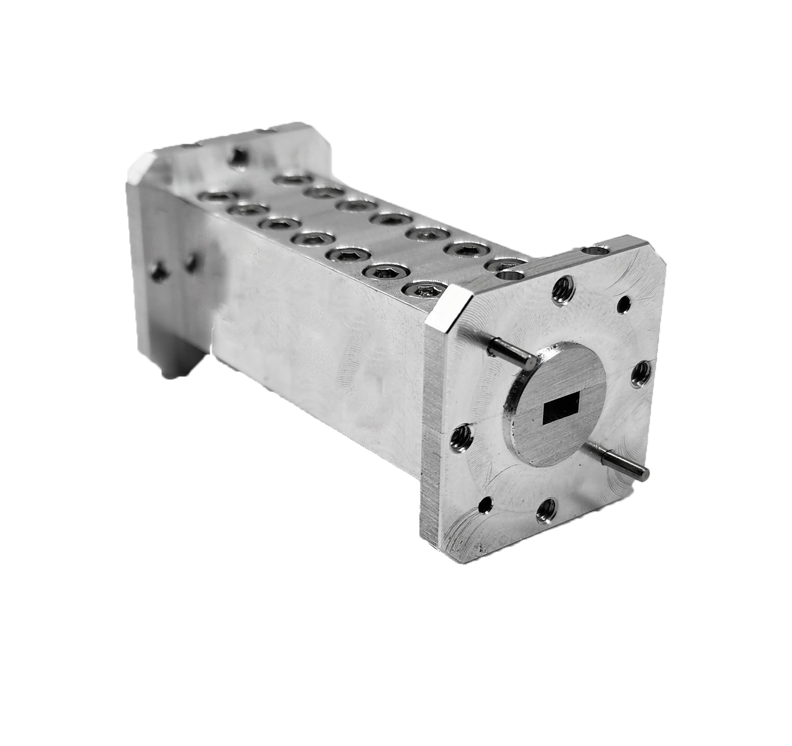
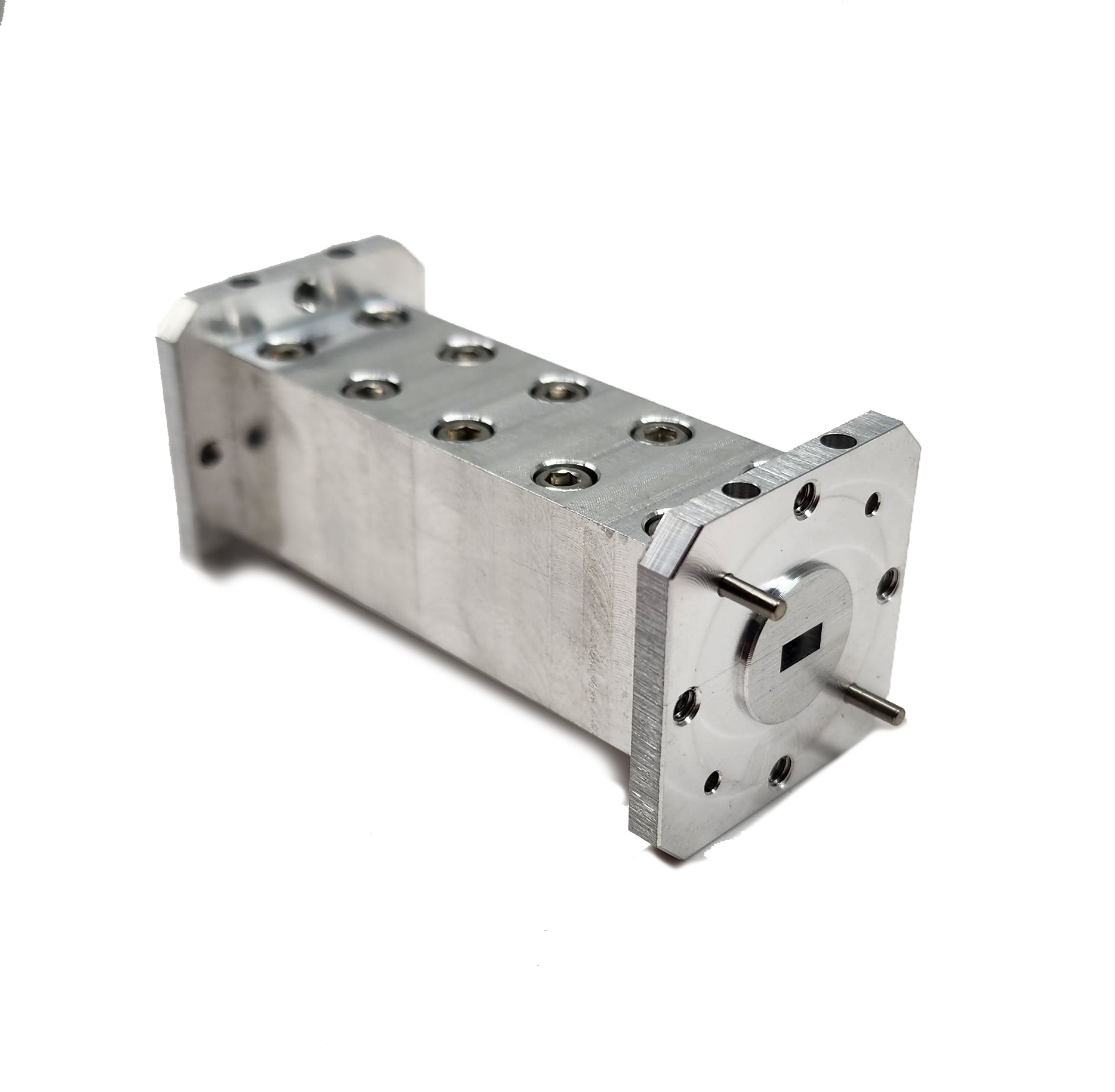
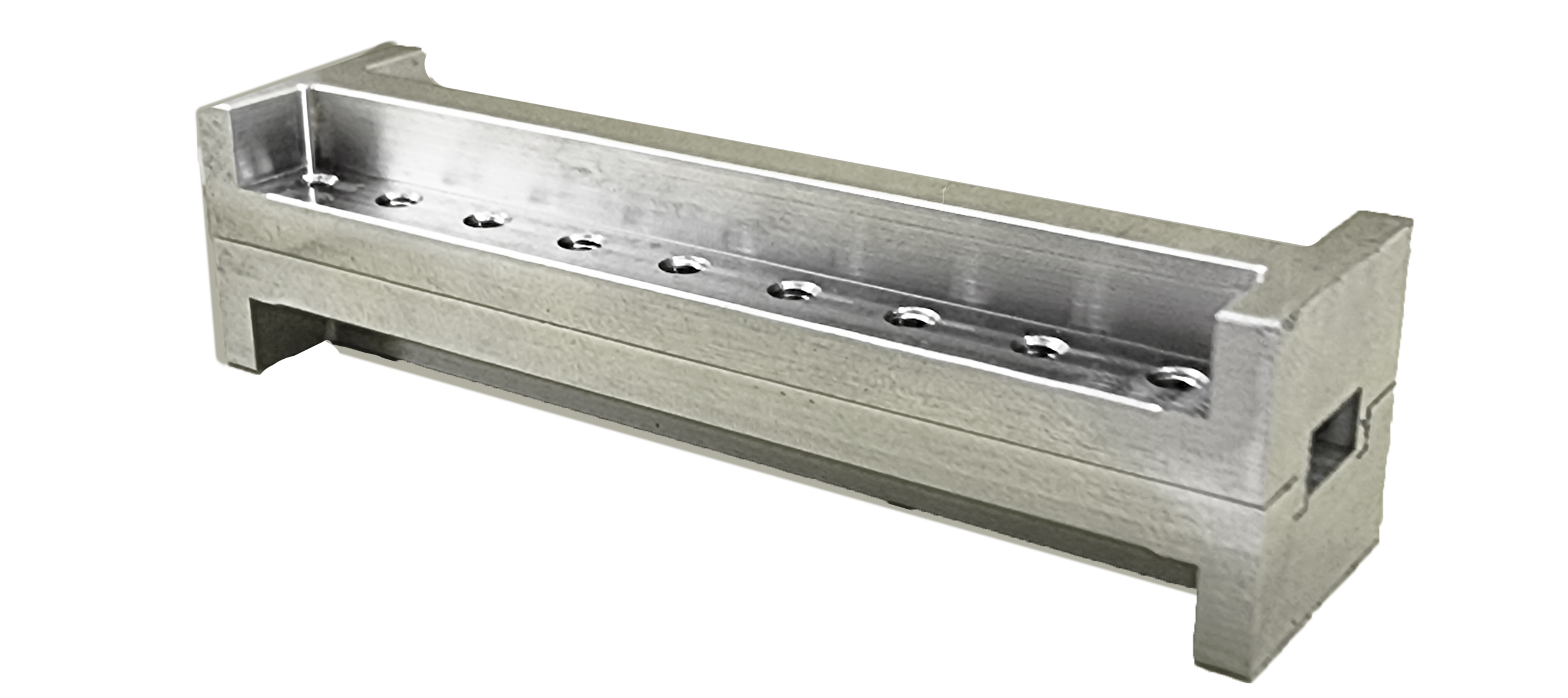
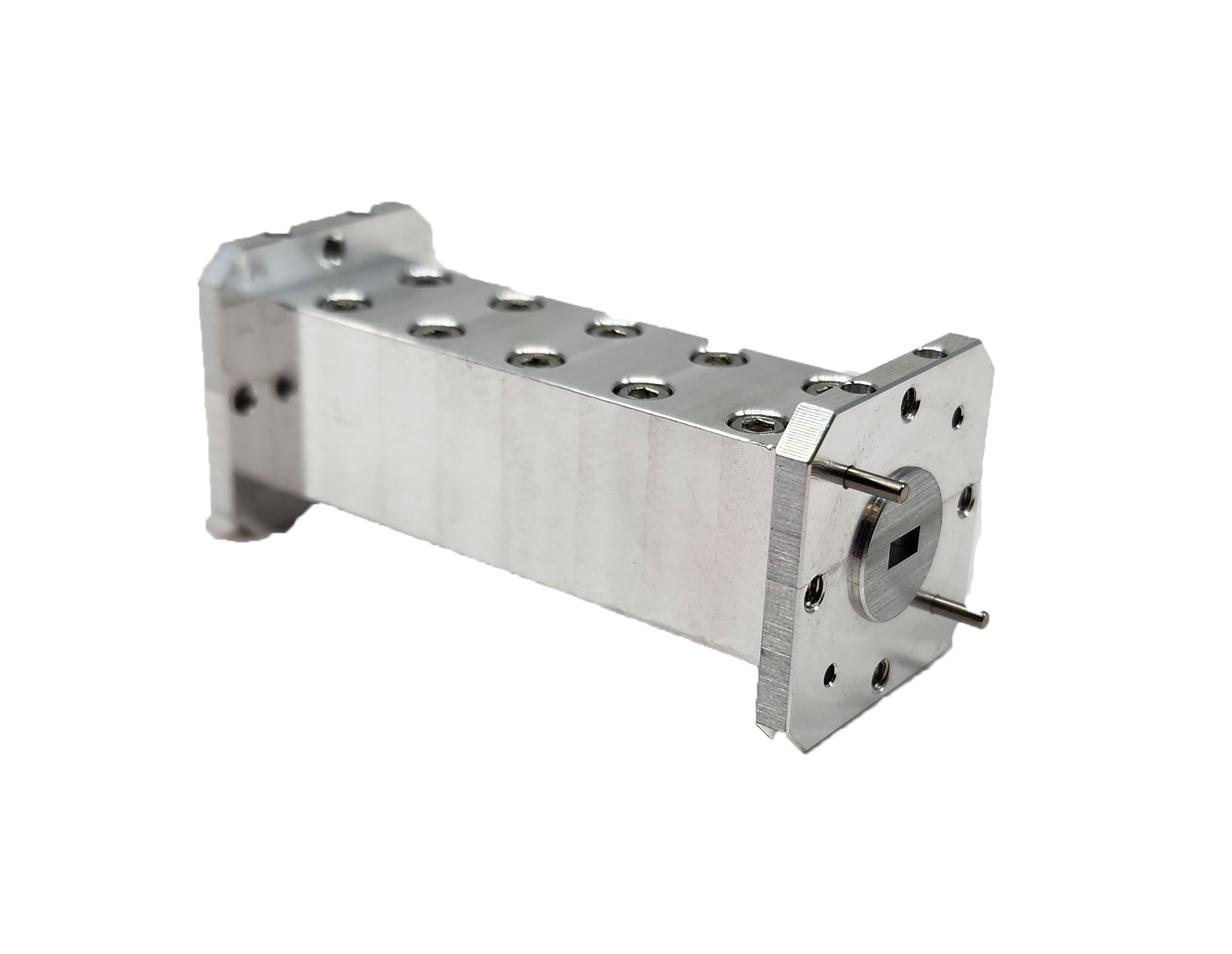
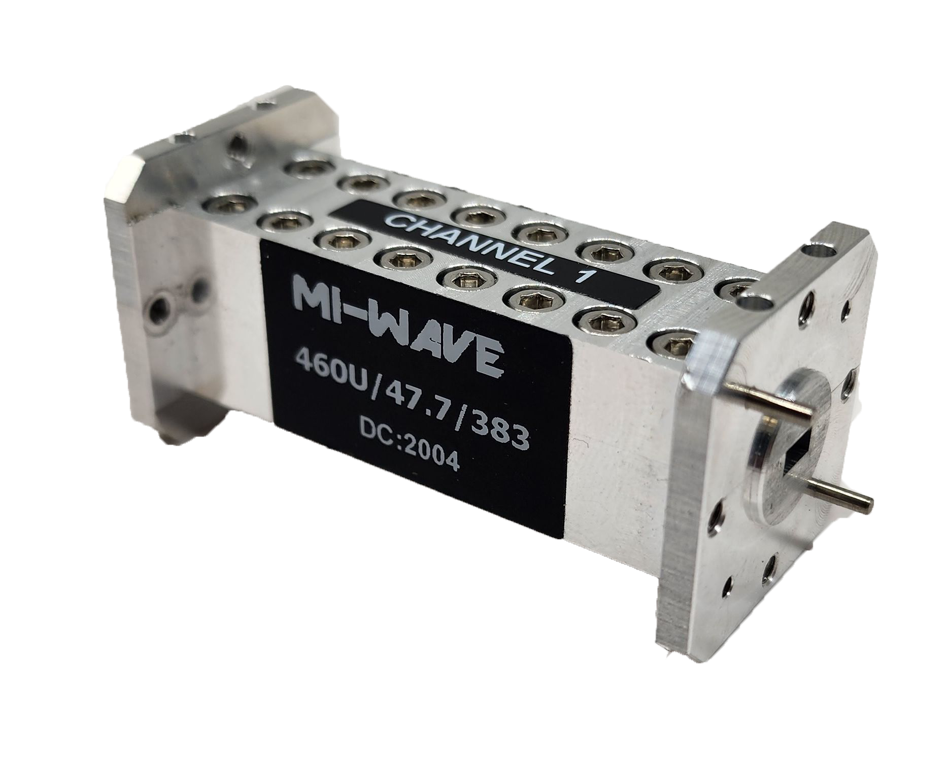
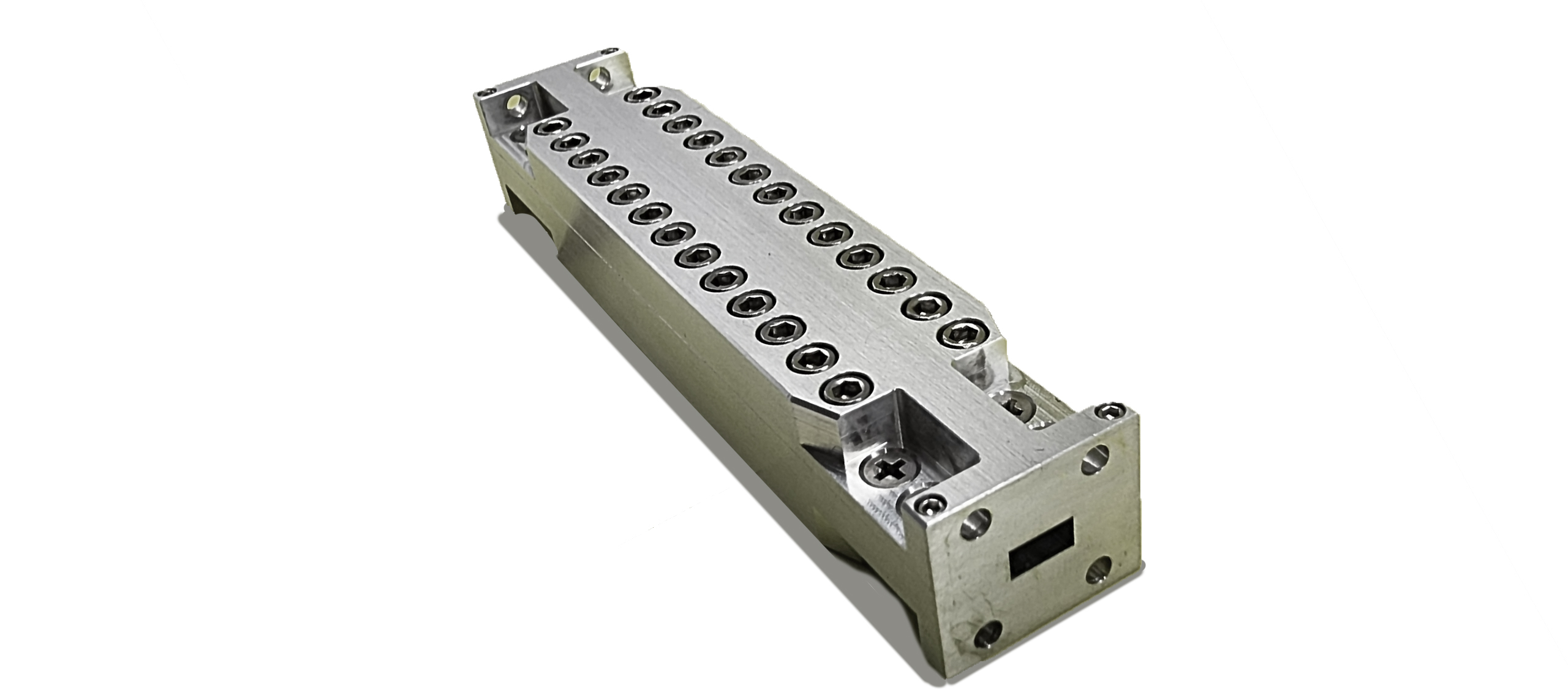
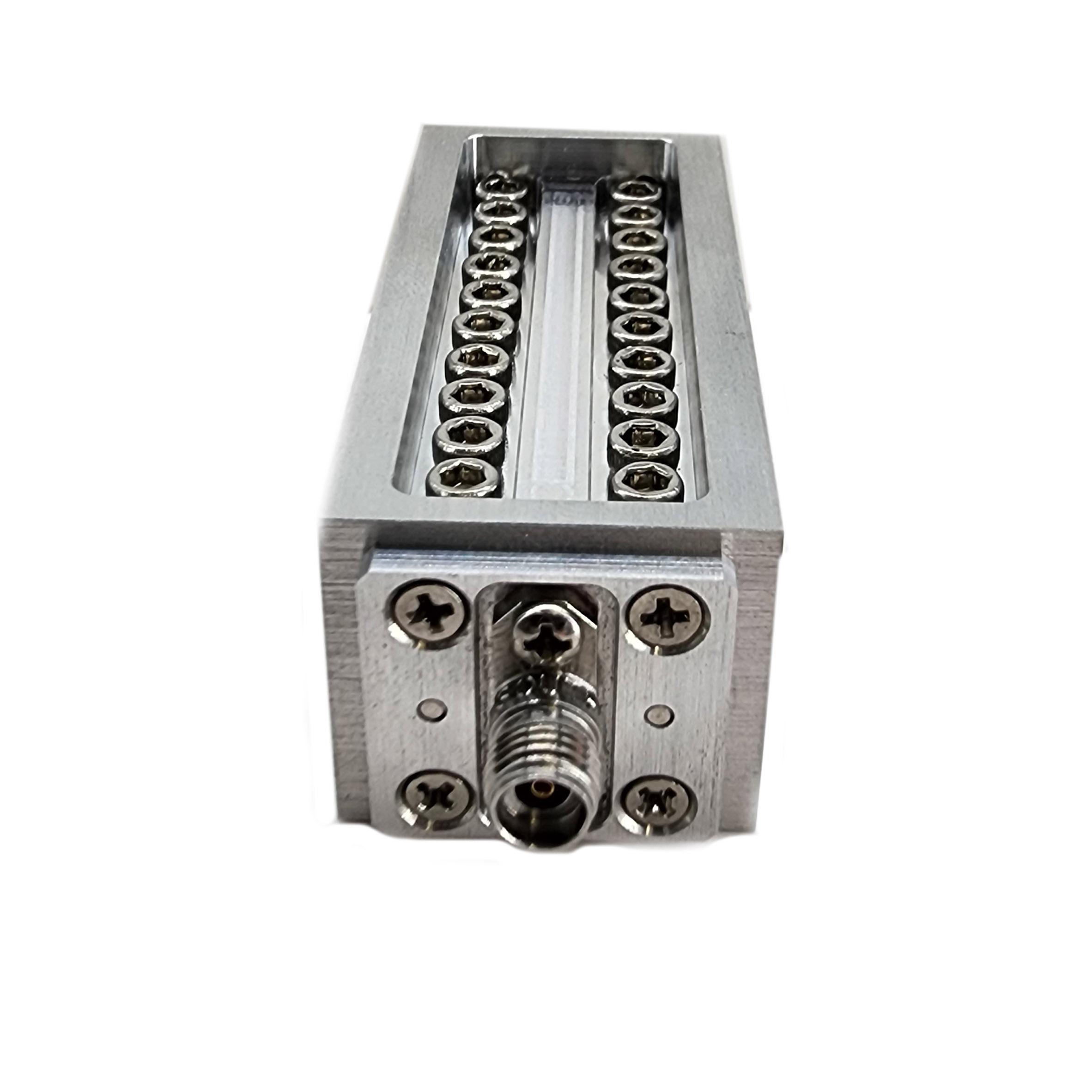
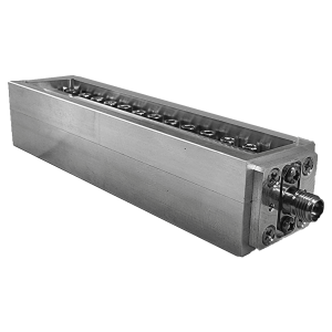
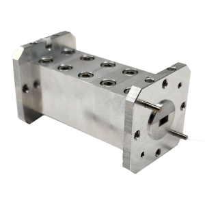
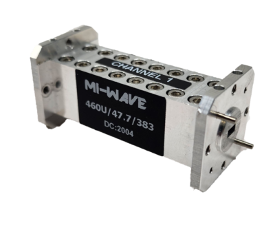
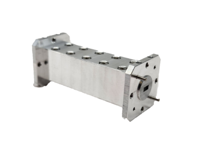
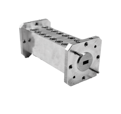
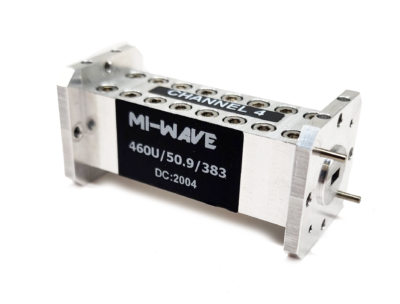
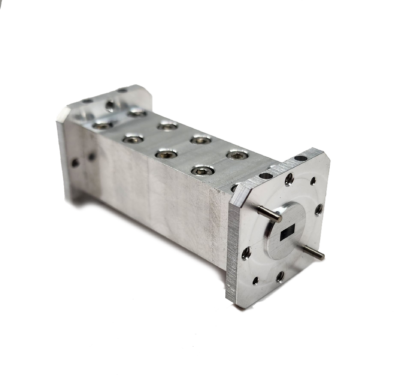
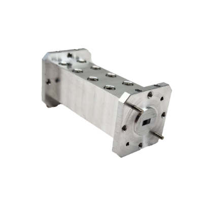
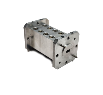
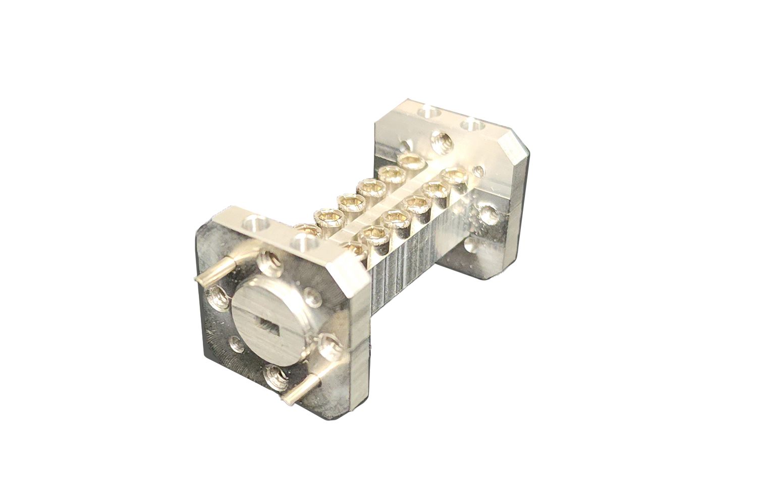
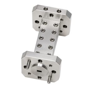
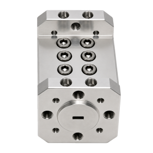
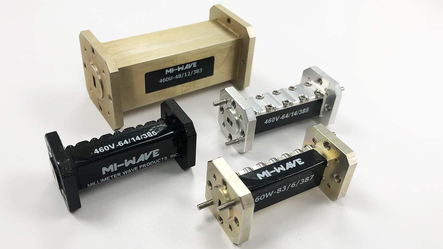
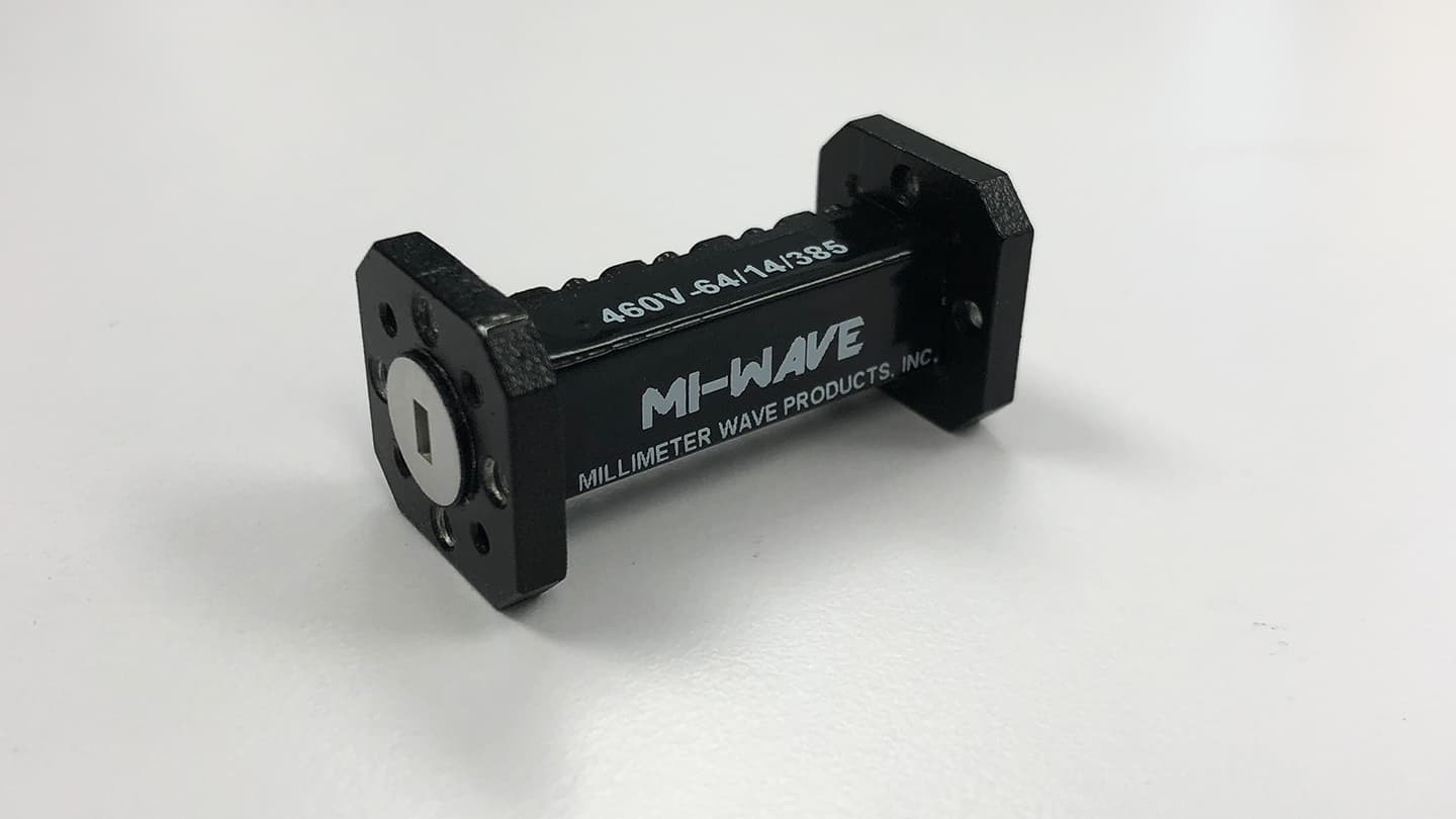
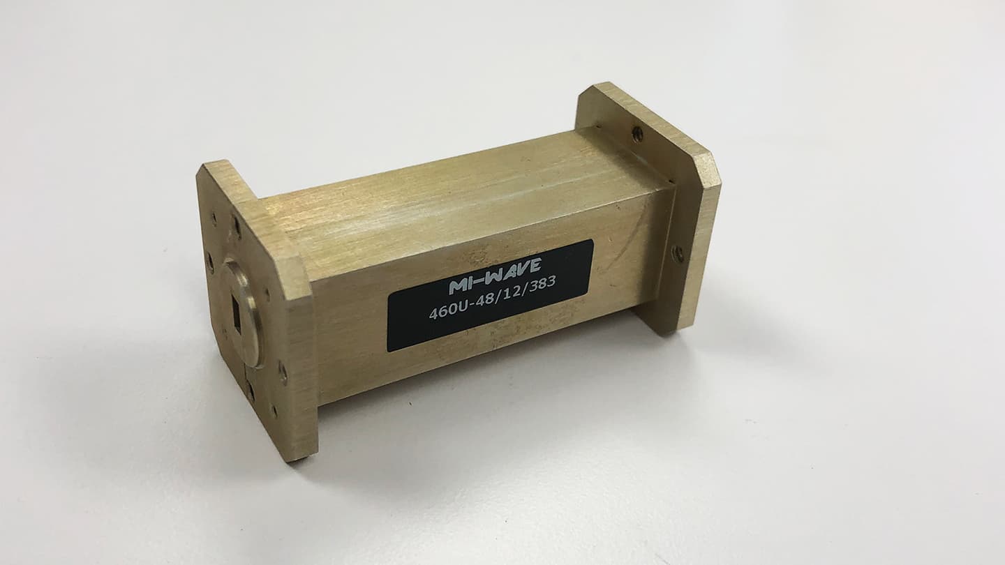
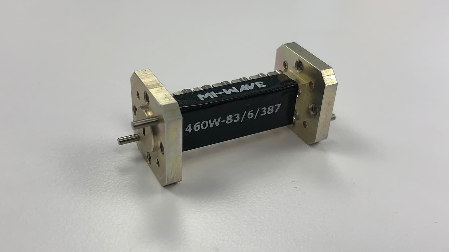
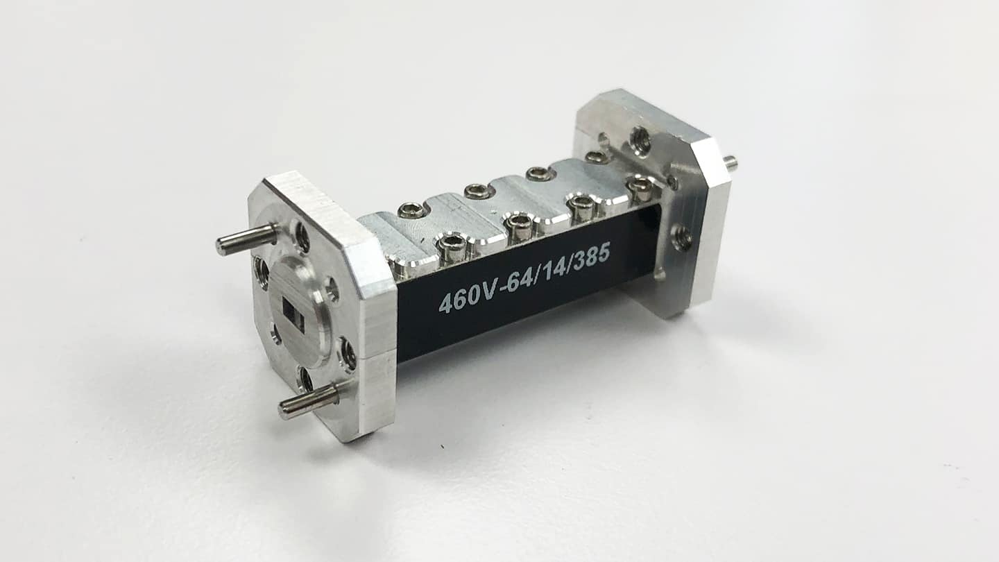
The MIWV 460 Series waveguide bandpass filters are high-performance frequency-selective components engineered to pass a defined range of RF, microwave, or millimeter-wave frequencies while rejecting unwanted signals outside the passband. As precision waveguide bandpass filter solutions, these units are designed for demanding high-frequency systems where low insertion loss, high rejection, and repeatable performance are critical — including radar, satellite communications, electronic warfare, and test & measurement applications.
The 460 Series is widely used in satellite communications, radar systems, electronic warfare platforms, test and measurement equipment, and advanced wireless communication systems.
Note: The RF bandpass filters shown on this website represent only a portion of MI-Wave’s manufacturing capabilities. MI-Wave designs and builds additional bandpass filter configurations beyond those listed, including custom frequency ranges, bandwidths, rejection levels, mechanical interfaces, and environmental options. Consult with MI-Wave to discuss your specific application requirements.


| Min Passband Frequency (GHz) | Max Passband Frequency (GHz) | Min Rejection Frequency Low (GHz) | Max Rejection Frequency Low (GHz) | Min Rejection Frequency High (GHz) | Max Rejection Frequency High (GHz) | Rejection (dB) | Waveguide Port |
|---|---|---|---|---|---|---|---|
| 22 | 32 | DC | 18 | 37 | 75 | 40 | WR-28 |
| 22 | 35 | DC | 20 | 40 | 72 | 40 | WR-28 |
| 22 | 38 | DC | 19.6 | 41 | 45 | 50 | WR-28 |
| 22 | 42 | DC | 20 | 48 | 95 | 60 | WR-28 |
| 27.5 | 32.5 | DC | 23.5 | 36.5 | 41.5 | 40 | WR-28 |
| 29 | 35 | DC | 27 | 37 | 45 | 40 | WR-28 |
| 30 | 45 | DC | 28 | 47 | 90 | 40 | WR-22 |
| 30 | 50 | DC | 25 | 56 | 100 | 40 | WR-22 |
| 32 | 38 | DC | 28 | 40 | 46 | 40 | WR-28 |
| 33 | 37 | DC | 31 | 39 | 46 | 40 | WR-28 |
| 33 | 50 | DC | 25 | 56 | 60 | 40 | WR-22 |
| 34 | 67 | DC | 30 | 69 | 120 | 40 | WR-19 |
| 35.26 | 36.26 | DC | 33.9 | 38 | 45 | 40 | WR-28 |
| 36 | 60 | DC | 29 | 66 | 120 | 40 | WR-19 |
| 40 | 50 | DC | 34 | 57 | 65 | 60 | WR-22 |
| 43 | 46 | DC | 42 | 47 | 55 | 30 | WR-22 |
| 47 | 57 | DC | 44 | 62 | 85 | 40 | WR-15 |
| 47 | 59 | DC | 44 | 63 | 78 | 50 | WR-15 |
| 49.75 | 50.25 | DC | 49 | 51 | 60 | 30 | WR-15 |
| 50 | 75 | DC | 44 | 80 | 110 | 40 | WR-15 |
| 51 | 55 | DC | 45 | 61 | 80 | 40 | WR-15 |
| 51.5 | 54.5 | DC | 44 | 62 | 70 | 40 | WR-15 |
| 53.5 | 54.5 | DC | 52 | 55 | 65 | 40 | WR-15 |
| 54.5 | 56.5 | DC | 53 | 57 | 70 | 50 | WR-15 |
| 55.75 | 56.25 | DC | 54.75 | 57.5 | 70 | 40 | WR-15 |
| 70 | 90 | DC | 60 | 93.3 | 130 | 40 | WR-12 |
| 71 | 76 | DC | 67 | 81 | 105 | 50 | WR-10 |
| 71 | 76 | DC | 67 | 81 | 105 | 50 | WR-12 |
| 73 | 76 | DC | 67 | 82 | 100 | 40 | WR-12 |
| 74 | 76 | DC | 70 | 80 | 100 | 40 | WR-12 |
| 75 | 78 | DC | 71 | 82 | 100 | 50 | WR-12 |
| 76 | 77 | DC | 74.5 | 78.5 | 90 | 50 | WR-10 |
| 76 | 81 | DC | 73 | 84 | 105 | 40 | WR-12 |
| 81 | 86 | DC | 78 | 88 | 120 | 50 | WR-10 |
| 81 | 86 | DC | 78 | 90 | 120 | 50 | WR-12 |
| 81 | 87 | DC | 78 | 90 | 120 | 30 | WR-12 |
| 82.5 | 85.5 | DC | 79 | 93.5 | 110 | 40 | WR-10 |
| 82.5 | 87 | DC | 80 | 90 | 120 | 40 | WR-12 |
| 90 | 98 | DC | 88 | 102 | 110 | 25 | WR-10 |
| 92 | 96 | DC | 90 | 98 | 130 | 40 | WR-10 |
| 92 | 100 | DC | 88 | 104 | 110 | 50 | WR-10 |
| 92.5 | 95.5 | DC | 91.5 | 97 | 97.5 | 20 | WR-10 |
| 93.2 | 95.2 | DC | 91 | 98.5 | 105 | 40 | WR-10 |
| 98 | 102 | DC | 95 | 105 | 110 | 40 | WR-10 |
Key Performance Features
460 Series Bandpass Filters are designed and manufactured to deliver consistent performance across a wide range of operating environments.
-
Frequency coverage from approximately 8 GHz to 140 GHz
-
Narrowband and wideband configurations with typical bandwidths from 1 percent to 10 percent of center frequency
-
Low insertion loss to preserve signal strength and system sensitivity
-
Low VSWR for improved impedance matching and reduced signal reflections
-
High out-of-band rejection to suppress harmonics, spurious signals, and adjacent channel interference
-
Waveguide interfaces matched to standard WR sizes across supported frequency bands
-
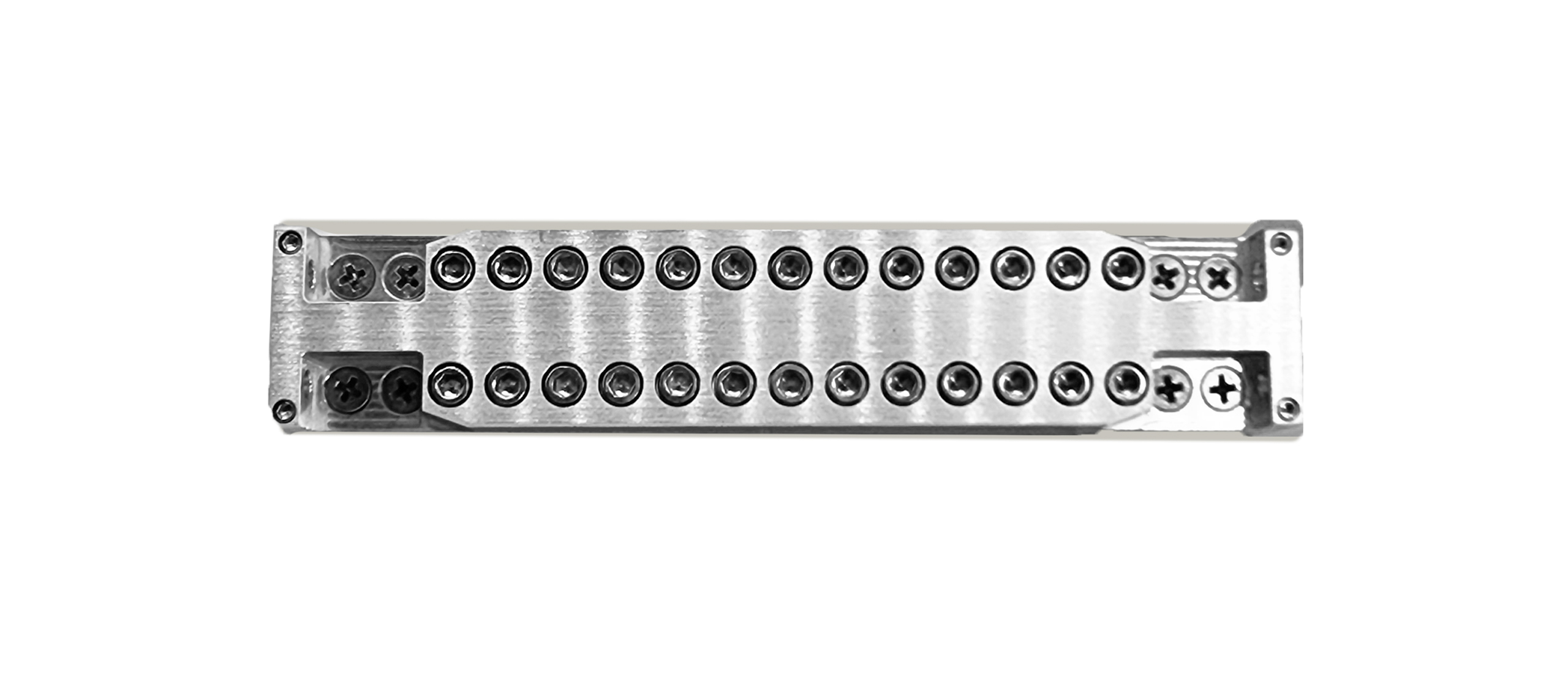
Precision-machined metal housings for mechanical stability and thermal consistency
-
Repeatable RF performance suitable for both lab and field applications
Applications for 460 Series Bandpass Filters
The MIWV 460 Series Bandpass Filters are designed for integration into a wide range of RF, microwave, and millimeter-wave systems where precise frequency selection, interference suppression, and signal integrity are essential. These filters are commonly used in both commercial and defense-grade platforms, supporting fixed, mobile, airborne, and space-constrained applications.
Satellite Communications (SatCom)
460 Series bandpass filters are widely used in satellite communication systems to isolate uplink and downlink frequency bands, suppress out-of-band interference, and protect sensitive receiver components.
Typical SatCom applications include:
-
Ground-based satellite terminals and gateway stations
-
Airborne and maritime SatCom platforms
-
Ka-band and Q-band satellite uplinks and downlinks
-
Payload frequency management and channel isolation
-
Interference mitigation in crowded satellite frequency allocations
-
Protection of LNAs, BUCs, and frequency converters
These filters help improve link stability, reduce noise, and maintain regulatory compliance in high-density satellite environments.
Radar Systems
In radar applications, 460 Series bandpass filters are used to improve target detection, reduce clutter, and protect receiver front ends from unwanted signals.
Common radar uses include:
-
Fire-control and target-tracking radar
-
Surveillance and perimeter monitoring radar
-
Imaging and high-resolution radar systems
-
Ground-based, airborne, and maritime radar platforms
-
Harmonic suppression in high-power radar transmit chains
-
Receiver protection from strong out-of-band signals
By tightly controlling the radar operating band, these filters enhance signal-to-noise ratio and overall system performance.
Electronic Warfare and Signal Intelligence (EW / SIGINT)
Electronic warfare and SIGINT systems require high selectivity and strong out-of-band rejection, making the 460 Series well suited for these mission-critical applications.
Use cases include:
-
Threat signal isolation and monitoring
-
Interference and jamming mitigation
-
Spectrum surveillance and signal collection
-
Front-end filtering for wideband receivers
-
Channelized receivers and frequency-selective architectures
-
Protection of sensitive EW receiver chains
The robust mechanical construction and repeatable RF performance make these filters suitable for deployed EW systems.
RF Upconversion and Downconversion Chains
460 Series Bandpass Filters are commonly integrated into frequency conversion architectures to remove unwanted mixer products and spurious signals.
Applications include:
-
RF upconverters and downconverters
-
Block upconverters (BUCs) and low-noise block downconverters (LNBs)
-
Intermediate frequency (IF) and RF stage filtering
-
Harmonic and image rejection after mixing stages
-
Clean signal generation for transmit chains
These filters help maintain spectral purity and prevent interference between system stages.
Test and Measurement Systems
In laboratory and production environments, 460 Series bandpass filters are used to ensure accurate, repeatable measurements at high frequencies.
Typical test applications include:
-
Millimeter-wave test benches and calibration setups
-
Signal generators and spectrum analyzers
-
Automated test equipment (ATE)
-
Device characterization and validation
-
Noise figure and linearity measurements
-
Production testing of RF and mmWave components
Their stable performance makes them ideal for R&D and manufacturing environments.
High-Data-Rate Wireless and Point-to-Point Links
460 Series bandpass filters support high-frequency wireless communication systems where spectral efficiency and interference control are critical.
Applications include:
-
Point-to-point microwave and millimeter-wave backhaul
-
Fixed wireless access (FWA) systems
-
High-capacity data links
-
Short-range high-bandwidth communication systems
-
Experimental and emerging wireless technologies
These filters help maintain link reliability in dense RF environments.
Scientific, Aerospace, and Research Applications
460 Series filters are also used in scientific instrumentation and advanced research platforms that operate at microwave and millimeter-wave frequencies.
Examples include:
-
Radio astronomy and remote sensing systems
-
Atmospheric and environmental monitoring instruments
-
University and government research laboratories
-
Spaceborne and airborne experimental payloads
-
Advanced sensing and imaging platforms
System Protection and Interference Mitigation
Across all industries, 460 Series Bandpass Filters are used to:
-
Protect sensitive RF receivers from overload
-
Suppress out-of-band noise and interference
-
Improve system dynamic range
-
Maintain compliance with spectral regulations
-
Enhance overall RF system reliability
Glossary of RF Bandpass Filter Terms
Core Frequency Definitions
Passband
The frequency range transmitted through the bandpass filter with minimal attenuation. Signals within the passband experience low insertion loss and are preserved for further processing in the RF signal chain.
Stopband
Frequency ranges outside the passband that are strongly attenuated by the filter. Stopbands are designed to suppress unwanted signals, noise, harmonics, and interference.
Cutoff Frequency
The frequency at which signal attenuation reaches a specified reference level relative to the passband, most commonly 3 dB. The lower cutoff frequency (f1) and upper cutoff frequency (f2) define the edges of the passband.
Center Frequency (fc)
The midpoint of the passband, calculated from the lower and upper cutoff frequencies. Center frequency is used as a reference for defining filter performance, bandwidth, and fractional bandwidth.
Bandwidth and Selectivity
Bandwidth (BW)
The width of the passband, defined as the difference between the upper and lower cutoff frequencies (f2 − f1). Bandwidth directly impacts channel selectivity and interference rejection.
Fractional Bandwidth (FBW)
Bandwidth normalized to center frequency (BW/fc). Fractional bandwidth is commonly expressed as a percentage and is widely used in RF specifications, datasheets, and RFQs to compare filters operating at different frequency ranges.
Q Factor
A measure of filter selectivity related to the ratio of center frequency to bandwidth (fc/BW). Higher Q indicates a narrower passband and greater selectivity.
Loss and Matching Parameters
Insertion Loss (S21)
The amount of signal power lost through the filter within the passband, typically measured in decibels. Low insertion loss is critical for maintaining system noise figure, signal strength, and link margin.
Return Loss (S11)
A measure of reflected RF power caused by impedance mismatch at the filter input or output. Higher return loss values indicate better impedance matching and lower reflections.
VSWR (Voltage Standing Wave Ratio)
A ratio derived from the reflection coefficient that indicates impedance matching quality. Lower VSWR values correspond to improved power transfer and reduced stress on RF components such as amplifiers and mixers.
Rejection and Interference Control
Out-of-Band Rejection
The attenuation provided outside the passband to suppress unwanted signals, harmonics, spurious emissions, image frequencies, and adjacent-channel interference. High out-of-band rejection is critical in dense RF environments.
Skirt Selectivity
The steepness of attenuation at the edges of the passband. Steeper skirts indicate higher selectivity and improved separation between desired and undesired signals.
Filter Structures and Implementations
Waveguide Bandpass Filter
A bandpass filter implemented using waveguide resonant structures to achieve low insertion loss, high power handling, and stable performance at microwave and millimeter-wave frequencies. Commonly used in SatCom, radar, and aerospace systems.
Cavity Filter
A type of bandpass filter that uses metallic resonant cavities to define the passband and rejection characteristics, offering excellent selectivity and power handling.
Resonator
A structure within a filter that stores electromagnetic energy at a specific frequency. Multiple resonators are coupled together to form a bandpass filter response.
Measurement and Performance Metrics
S-Parameters
Scattering parameters used to characterize RF components. For bandpass filters, S11 represents input reflection (return loss) and S21 represents forward transmission (insertion loss).
Insertion Loss Flatness
The variation of insertion loss across the passband. Low ripple or flat insertion loss is important for maintaining consistent signal amplitude.
Group Delay
The frequency-dependent time delay introduced by the filter. Excessive group delay variation can distort wideband or digitally modulated signals.
Application and System-Level Terms
Receiver Front-End Protection
The use of bandpass filters to prevent strong out-of-band signals from overloading low-noise amplifiers and mixers.
Image Frequency Rejection
Suppression of unwanted image frequencies generated in frequency conversion stages.
Harmonic Suppression
Reduction of harmonic signals produced by nonlinear RF components.
Spectral Compliance
Ensuring transmitted signals meet regulatory emission and spectral mask requirements.


Why Choose MI-Wave
Millimeter Wave Products Inc. (MI-Wave) delivers high-performance RF, microwave, and millimeter-wave bandpass filters backed by decades of proven engineering expertise. Our 460 Series Bandpass Filters are trusted in satellite communications, radar, electronic warfare, and test environments where performance and reliability matter.
Over 35 years of experience in high-frequency RF design ensures every filter is optimized for low insertion loss, low VSWR, and strong out-of-band rejection.
MI-Wave offers full in-house design, machining, assembly, and testing, providing tighter quality control, faster response times, and consistent performance across production runs.
Our product portfolio combines standard configurations with custom design capability, allowing filters to be tailored for specific frequencies, bandwidths, mechanical interfaces, and system requirements.
As a U.S.-based manufacturer, MI-Wave provides responsive engineering support and dependable sourcing for both commercial and defense-related programs.
MI-Wave is more than a component supplier. We are a long-term RF partner focused on reliable performance, seamless system integration, and sustained program success.
Have questions or need help selecting the right 460 Series Bandpass Filter for your application? The MI-Wave team is available to support both standard product selection and custom RF filter solutions.
Our engineers and sales team can assist with frequency selection, bandwidth requirements, mechanical interfaces, and system integration considerations for RF, microwave, and millimeter-wave applications.
What Are Bandpass Filters?
A bandpass filter is a frequency-selective RF component that allows signals within a defined
frequency range, known as the passband, to pass with minimal attenuation while rejecting
frequencies outside that range. In practical RF systems, bandpass filters help engineers control spectrum usage,
reduce interference, and maintain signal integrity across RF, microwave, and millimeter-wave
signal chains.
Bandpass filters are often placed at key points in a system where frequency selectivity matters most, including
receiver front ends, transmitter chains, IF stages,
upconverters and downconverters, LO paths, and test ports.
By passing only the desired band and suppressing out-of-band energy, RF bandpass filters improve performance in
real-world environments where harmonics, spurious signals, and
adjacent-channel interference are common.
RF bandpass filters are commonly used in satellite communications (SatCom),
radar systems, electronic warfare (EW), SIGINT/COMINT,
wireless backhaul links, aerospace systems, and RF test and measurement equipment.
At higher frequencies, especially microwave and millimeter-wave bands, precise filtering is required to protect
sensitive receiver components such as low-noise amplifiers (LNAs) and to prevent overload, desensitization,
and intermodulation in mixers and converters.
How Do Bandpass Filters Work?
Bandpass filters operate by combining the behavior of a high-pass filter and a
low-pass filter into one frequency-selective response. Frequencies below the
lower cutoff frequency (f1) are attenuated, frequencies above the
upper cutoff frequency (f2) are attenuated, and frequencies within the passband are transmitted
with low insertion loss. This selectivity allows the filter to isolate a target signal band while suppressing
out-of-band noise and interference.
In microwave and millimeter-wave bandpass filters, frequency selectivity is typically achieved using resonant structures
such as waveguide cavity resonators, coupled resonators, and iris-coupled filter sections.
Each resonant section reinforces the desired frequencies and contributes to the overall attenuation slope (filter skirts) outside the passband.
The number of resonators and the coupling strategy influence selectivity, bandwidth, and stopband rejection.
Bandpass filters are specified and evaluated using S-parameters, where S21 represents transmission
(insertion loss) and S11 represents reflection (return loss). In production environments, filter performance is verified
on a vector network analyzer (VNA) to confirm passband loss, cutoff behavior, stopband attenuation, and impedance matching.
MI-Wave bandpass filters are precision-machined to tight mechanical tolerances to help ensure repeatable electrical performance,
stable frequency response, and low loss across temperature and environmental conditions. For demanding RF environments, mechanical design
and fabrication quality are essential to maintain consistent performance at high frequencies.
Key Bandpass Filter Parameters and Formulas
Center Frequency
The center frequency (fc) represents the midpoint of the passband and is calculated as:
fc = (f1 + f2) / 2
Where f1 is the lower cutoff frequency and f2 is the upper cutoff frequency.
Center frequency is commonly used as the reference point for defining filter performance, comparing filter families,
and calculating fractional bandwidth and Q factor.
Bandwidth
The bandwidth (BW) defines the width of the frequency range allowed to pass:
BW = f2 − f1
Bandwidth directly impacts channel selectivity, interference rejection, and overall RF system performance.
Narrower bandwidth filters improve selectivity but may require higher-order designs and can increase insertion loss.
Fractional Bandwidth
Fractional bandwidth (FBW) is commonly used in RF and microwave filter specifications and is defined as:
FBW = (f2 − f1) / fc
FBW makes it easier to compare filter selectivity across frequency bands. In procurement and engineering discussions, FBW is often expressed
as a percentage and is frequently included in RFQ documentation. MI-Wave 460 Series Bandpass Filters can be configured across a range of
fractional bandwidths depending on frequency band, rejection requirements, and mechanical implementation.
Insertion Loss
Insertion loss represents the signal power lost when the filter is placed in the signal path and is typically measured in dB
within the passband. Low insertion loss is critical for maintaining signal strength, preserving system noise figure, and improving link margin
in RF communication systems. In receiver chains, excess insertion loss reduces sensitivity; in transmitter chains, it reduces delivered output power.
Return Loss and VSWR
Return loss and Voltage Standing Wave Ratio (VSWR) describe how well the filter is impedance-matched to the RF system.
Good impedance matching improves power transfer and minimizes reflections that can stress amplifiers, degrade EVM in digital modulation, or create standing waves.
VSWR is calculated as:
VSWR = (1 + |Γ|) / (1 − |Γ|)
Where |Γ| is the magnitude of the reflection coefficient. Lower VSWR indicates reduced reflection, improved matching, and more stable
operation across the intended frequency band.
Out-of-Band Rejection
Out-of-band rejection defines how effectively unwanted frequencies are attenuated outside the passband. High rejection is essential for
suppressing harmonics, spurious emissions, image frequencies, and
adjacent-channel interference in dense RF environments. Strong rejection also helps protect front-end components from overload and improves
overall system dynamic range.
Why Bandpass Filters Are Critical in RF Systems
- Isolating desired frequency channels in multi-signal environments
- Reducing electromagnetic interference (EMI) and broadband noise
- Protecting LNAs, mixers, and receivers from overload and desensitization
- Improving signal-to-noise ratio (SNR) and receiver sensitivity
- Reducing intermodulation products by limiting out-of-band energy entering nonlinear stages
- Maintaining spectral compliance and minimizing unwanted emissions
- Enhancing long-term reliability by improving impedance matching and reducing reflected power
Bandpass Filters vs Other RF Filter Types
- Low-pass filters allow frequencies below a cutoff to pass and attenuate higher frequencies
- High-pass filters allow frequencies above a cutoff to pass and attenuate lower frequencies
- Bandstop (notch) filters reject a specific frequency range while passing frequencies outside that range
- Bandpass filters pass only a selected frequency range and reject frequencies below and above the passband