
How to Select a Millimeter Wave Isolator
As frequencies climb into the millimeter-wave range, wavelengths shrink to a few millimeters and small imperfections start to matter. A reflection that would be negligible at S-band can be large enough at W-band to pull an oscillator off frequency or put ripple on an amplifier’s gain.
That makes the isolator one of the most useful small parts in a mm-wave chain, and one of the easiest to specify carelessly. Band, topology, size, and magnetic environment all shape the right choice, and each is worth settling before a part number is picked.
What a Millimeter Wave Isolator Does
A millimeter wave isolator is a passive, non-reciprocal device that lets signal pass in one direction with low loss and blocks it in the other. Ferrite material biased by a permanent magnet produces that behavior through Faraday rotation, and some designs use a controlled 45-degree rotation to steer energy. Reverse energy is dissipated as heat in an internal absorptive load, so nothing is sent back to the source.
No external power is needed for the Faraday designs, which is part of why isolators are easy to add to an existing signal path once the right one is chosen.
Choose the Right Topology
Mi-Wave offers three isolator families, and each suits a different integration situation:
- Faraday Isolators (Series 115): built with an integral permanent magnet and operating passively, a conventional choice for waveguide signal paths.
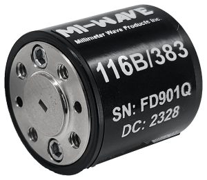
- Compact Isolators (Series 116): a smaller package suited to modules where space and weight are tight.
- Y-Junction Isolators (Series 178): a ferrite-junction design in which reverse energy is routed to an absorptive termination instead of back to the source.
Choose based on the space available, the waveguide layout, and how the isolator will mount in your assembly. Where the requirement is unusual, ask about the best fit for your band.
Start With Your Frequency Band
Isolators are built for a defined operating band and a matching waveguide size. The range covered here runs from roughly 18 GHz to 325 GHz, and full-band performance is offered on select designs only, not across the board. Confirm the exact band your system uses and match it to the standard waveguide size, then check the performance across the whole band. Parts tend to perform best near the center of their range, so a system running near a band edge deserves a closer look at the numbers.
Weigh Isolation, Insertion Loss, and VSWR Together
At millimeter-wave frequencies these three figures trade off against each other, so reading one in isolation can mislead you. Isolation tells you how well reflections are blocked, and a higher figure better protects the amplifier or oscillator behind the isolator. Insertion loss comes straight off your link budget, so a lossy isolator can cost more output than the protection is worth. VSWR describes how well the ports match, and a poor match produces reflections of its own.
Request all three across your operating band, not at one frequency, and decide which matters most for the stage being protected. A power amplifier output usually cares most about insertion loss, while a sensitive oscillator cares most about isolation.
Plan for Size, Weight, and Flange Fit
Waveguide isolators come with a fixed flange type and port orientation, and the dimensions at mm-wave bands leave little room for adapters. An adapter adds insertion loss, another VSWR discontinuity, and a joint that has to be aligned precisely. Confirm flange type, port spacing, and overall envelope against your module layout before ordering, particularly in tightly packed transmit or receive assemblies.
Keep the Magnetic Environment in Mind
The permanent magnet that makes the isolator work also produces a field around the housing. As a general practice, keep ferrous parts and other magnets away from it, and give neighboring isolators enough spacing that their fields do not interact. Check the operating temperature range too, since ferrite behavior and magnetic bias can drift with temperature, and confirm the part performs at the extremes your system will see.
Match the Isolator to the Application
Test and measurement setups use isolators to keep sources stable when the device under test reflects. Amplifier protection is another common role, with the isolator placed ahead of an antenna or load that may not be perfectly matched. Radar and SatCom front ends rely on them in transmit chains, and frequency conversion assemblies use them to prevent reflections from disturbing local oscillators and mixers. Aerospace and defense systems, including electronic warfare, ELINT, SIGINT, and secure communications, depend on them for the same reasons, as do research setups and integrated RF subsystems.
Common Selection Mistakes to Avoid
- Picking by band alone: without checking isolation and VSWR at the actual operating frequencies.
- Assuming full-band coverage: when only select designs are rated for it.
- Ignoring the magnet: by mounting the isolator beside steel hardware or another magnetized part.
- Accepting loss you don’t need: by choosing high isolation for a stage that is more sensitive to insertion loss.
- Adding adapters: to fit a mismatched flange instead of choosing the right interface up front.
Where This Kind of Component Comes From
Millimeter-wave isolators come from a small number of specialized manufacturers, since holding performance at these dimensions takes precision machining and controlled assembly. Mi-Wave is one of them, building isolators alongside a wider catalog of waveguide components and subsystems for radar, satellite, and test applications.
Conclusion
Choosing a millimeter wave isolator isn’t about finding the part with the biggest isolation number. It is about matching the topology and band to your assembly, weighing isolation against insertion loss for the stage you are protecting, and confirming the flange and magnetic environment fit your layout. Get those right and the isolator quietly keeps reflections from reaching the parts that cannot tolerate them.
If you are choosing an isolator for a millimeter-wave module and want to work through band, topology, and fit before committing to a part, Contact Us and our engineering team can help match a configuration to your system.