
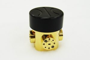
How to Choose a Waveguide Switch
The fastest way to turn a clean lab measurement into a suspect one is to route the signal through a component nobody bothered to characterize – and a switch sitting in the middle of that signal path is exactly that kind of component when it’s picked on price alone.
These switches show up in almost every test bench, radar front end, and multi-path RF system that needs to route a signal between two or more destinations without a manual connector swap. They look simple on a datasheet – a frequency range, an insertion loss number, a port count – but the gap between a unit that disappears into the system and one you end up troubleshooting every week comes down to a short list of specs most buyers skim past.
What This Kind of Switch Actually Does
A waveguide switch routes a microwave or millimeter-wave signal between one input and one of several output ports, or the reverse, using either a mechanical actuator or a solid-state element to move the signal path. Mechanical designs split into two groups: manually operated units, turned by hand for infrequent path changes, and solenoid-actuated units, which move a rotor electrically on command and are built for remote or automated control. A separate category, PIN diode designs, uses biased semiconductor junctions instead of moving parts, trading a small amount of insertion loss for switching speeds mechanical designs can’t match. Picking between them is the first real decision in this selection process, and it depends entirely on how often the path needs to change and how fast that change has to happen.
Once actuation type is settled, the next thing to lock down is which band and port configuration the unit actually needs to cover.
Match Frequency Band and Port Configuration
These switches are built around a specific band and waveguide size – coverage across the standard catalog runs from about 18 GHz up past 220 GHz across the K, Ka, Q, U, V, E, W, F, D, and G bands, each tied to its own waveguide flange. Configuration matters just as much as frequency: an SPDT (single-pole double-throw) unit routes a signal between one of two paths, while an SP4T (single-pole four-throw) unit extends that to four, which is common in multi-antenna or multi-instrument test setups. Confirm both the exact band and the port count before ordering – a unit built for one waveguide size won’t mate with a different one without an adapter, and every adapter added to the chain reintroduces the loss and reflection problems it was meant to route around cleanly. For a system that needs to route between two or four fixed paths without a manual connector swap, a waveguide switch is usually the simplest way to do it electrically.
With band and configuration set, the numbers that determine how much the unit actually degrades your signal come next.
Check Insertion Loss and Isolation
A few datasheet numbers do more to predict real-world performance than the rest combined:
- Insertion loss: how much signal strength is lost passing through the “on” path; well-built electromechanical designs typically run 0.3-0.5 dB through most bands, climbing to 0.8-1.3 dB at the highest millimeter-wave frequencies.
- Isolation: how well the unit blocks signal from reaching a port that isn’t selected; 60-70 dB is a reasonable target for most test and system applications.
- Power handling: confirm the rated power handling – 100W is common for electromechanical designs – covers your actual transmit levels, not just your nominal signal level.
Loss and isolation describe signal quality. Switching speed and control interface describe how well the unit fits into your system.
Confirm Switching Speed and Control Interface
Electromechanical designs typically complete a path change in well under a second – roughly half a second is standard – driven by a 12-15V DC bias and a TTL control signal, with GPIB (IEEE-488) control available on some models for automated test setups. PIN diode designs operate far faster, in the microsecond-to-nanosecond range, which matters for radar and EW applications that need to change signal paths within a single pulse. Manually operated units skip electronic control entirely and are best reserved for setups where the path only changes occasionally, such as calibration or bench reconfiguration between test runs. Matching switching speed to how the system actually uses it, rather than defaulting to the fastest option available, keeps both cost and complexity down.
Account for Duty Cycle and Environmental Rating
Actuation life matters more than most buyers initially budget for: a solenoid-actuated switch cycling continuously in an automated test rack racks up switch operations far faster than one flipped a few times a day in a fielded system, and mechanical wear eventually shows up as increased insertion loss or intermittent contact rather than sudden failure. Confirm the manufacturer’s rated cycle life against your expected duty cycle before committing to a design that switches thousands of times a day. Operating temperature range is the other number worth checking early – a unit qualified for a bench environment won’t necessarily hold its insertion loss and isolation specs across the temperature swings of an outdoor radome or an airborne pod, so match the environmental rating to where the unit will actually sit, not just to the lab it will be validated in.
Even with the electrical specs matched on a waveguide switch, a handful of avoidable mistakes account for most of the field issues with this class of component.
Common Selection Mistakes to Avoid
- Choosing a unit rated for the wrong actuation speed, then working around a system bottleneck a faster (or cheaper, slower) option would have avoided.
- Overlooking control voltage and signal type – TTL vs GPIB – until the system’s control electronics are already finalized.
- Assuming isolation figures at midband apply across the full rated frequency range, when they typically degrade toward the band edges.
- Adding a waveguide-size adapter to force a fit, instead of ordering the correct flange size from the start.
Where This Kind of Component Comes From
Hardware like this is produced by a small number of manufacturers with in-house waveguide machining and RF test capability, since flange tolerances and insertion-loss performance depend directly on manufacturing precision. Mi-Wave is one of the manufacturers building this class of component, offering manual, solenoid-actuated, and PIN diode switch lines alongside its broader catalog of millimeter-wave products.
Conclusion
Choosing the right switch comes down to matching actuation type and switching speed to how often and how fast the signal path actually needs to change, then confirming frequency band, port configuration, insertion loss, isolation, and power handling against your system’s real operating conditions rather than its nominal specs. Get those decisions right up front, and the switch becomes a routing component you never think about again, instead of the thing you’re troubleshooting six months into a program.
