
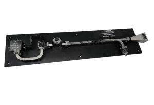
How to Choose a Radar Target Simulator
Testing a radar receiver against a real moving target means finding a real moving target, scheduling a range, and hoping the weather and the target both show up on the same day – or generating that same signal on a bench, on demand, as many times as the test plan requires.
That second option is what this kind of hardware is built for: reproducing the Doppler shift, delay, and signal characteristics of a moving radar return without ever leaving the lab. The specs that matter most – frequency coverage, Doppler range, signal purity, and how many targets it can represent at once – vary enough between models that matching the unit to the actual test requirement takes more than checking a single headline frequency number.
What a Target Simulator Actually Does
A radar target simulator takes an RF input and modulates it to reproduce the signal characteristics of a radar return from a moving object – shifting frequency to represent Doppler velocity, and in more advanced configurations, applying delay to represent range and combining multiple returns to represent several targets at once. Because the simulated signal has to stand in for a real physical return with enough fidelity to exercise the receiver and signal processor being tested, the unit’s own signal purity – its image rejection, spurious content, and phase noise – has to be clean enough that it doesn’t introduce artifacts the test is meant to catch in the target return itself. Selecting the right unit is really a signal-purity exercise wrapped around a Doppler-generation function, not just a matter of picking a frequency band.
Frequency coverage is still the first filter, since a unit built for one band won’t help with a receiver operating in another.
Match Frequency Coverage to Your Radar Band
These units are typically built around specific center frequencies spanning K through W-band – common configurations cover roughly 24 GHz, 35.5 GHz, 60 GHz, 76.5 GHz, and 94 GHz, aligning with automotive radar, weather radar, and various defense radar bands. Confirm the frequency matches your radar’s actual operating frequency, not just its band designation, since two systems in the same nominal band can center on different frequencies within it. Bandwidth around that center frequency also matters – a unit offering only ±50 MHz of adjustment range will represent a narrower range of closing speeds than one offering ±100 MHz, which matters directly for how wide a velocity range you can test. For radar receiver validation and automated test benches that need a repeatable, on-demand moving target, a radar target simulator removes the dependency on live-range testing entirely.
Once frequency and bandwidth line up, the numbers that determine how believable the simulated target actually looks come next.
Check Doppler Range, Image Rejection, and Loss
- Doppler / velocity range: confirm the adjustable frequency offset covers the closing and receding speeds your test plan requires, in both directions.
- Image rejection: measures how well the unit suppresses the unwanted sideband created during frequency shifting; look for at least -20 dBc, since a poorly rejected image shows up as a phantom second target in the test data.
- Conversion loss: the signal loss through the modulation path, typically in the 12-15 dB range depending on frequency – factor this into your test setup’s power budget so the receiver under test still sees an adequate signal level.
Those numbers describe a single simulated target. Most real test requirements need to represent more than one target, or more than one dimension of motion, at a time.
Confirm multi-Target and I/Q Control Capability
Basic configurations simulate a single target’s Doppler shift with a fixed or adjustable offset. More advanced setups use independent I/Q modulation to control both the magnitude and direction of the simulated velocity electronically, and can combine multiple modulation paths to represent several targets simultaneously – useful for testing a radar’s ability to discriminate between closely spaced returns rather than just detect a single one. Confirm the control interface, whether analog I/Q inputs or a digital control path, matches what your test setup can actually drive, since more capability than your control chain can exercise doesn’t add test value.
Check Repeatability and Calibration Traceability
A target simulator’s real value over live-range testing is repeatability: the same test run at the same settings should produce the same simulated target every time, so regression testing across firmware or hardware revisions actually means something. Confirm the manufacturer specifies gain and frequency accuracy against a calibration reference, not just a nominal output level, and ask how drift over temperature and time is characterized. For test programs that feed results into a qualification report, traceable calibration data is often as important as the raw Doppler and image-rejection numbers, since a test result nobody can defend under audit doesn’t hold up any better than no test at all.
Even with the electrical specs matched, a handful of avoidable mistakes account for most of the rework in target simulator selection.
Common Selection Mistakes to Avoid
- Matching the unit to a radar’s nominal band designation instead of its actual center operating frequency.
- Underestimating the Doppler range needed to cover the full closing-speed envelope the test plan requires.
- Overlooking image rejection, then misreading a phantom sideband as a second target during test analysis.
- Choosing a multi-target radar target simulator when the test plan only ever exercises single-target scenarios, adding cost and control complexity with no test benefit.
Where This Kind of Component Comes From
Hardware like this is built by specialized RF and microwave manufacturers rather than general test equipment vendors, since accurate Doppler and image-rejection performance depends on RF subsystem design experience specific to radar test applications. Mi-Wave is one of the manufacturers producing this class of equipment, with configurations spanning K-band through W-band alongside its broader catalog of millimeter-wave test and measurement hardware.
Conclusion
Selecting the right unit comes down to matching frequency coverage and Doppler range to your radar’s actual test requirements, then confirming image rejection and conversion loss hold up well enough that the simulated target doesn’t introduce artifacts of its own. Add multi-target or I/Q control capability only where the test plan actually calls for it. Get that matching right, and the simulator becomes a dependable stand-in for range testing – not another variable the test team has to account for.
