
How to Choose a Microwave Low Noise Amplifier
A receiver chain is only as sensitive as its first active stage – every dB of noise added before the signal reaches that first amplifier is a dB the rest of the system can never recover, no matter how good the components downstream are. That’s why choosing the wrong low noise amplifier doesn’t just underperform, it sets a ceiling on what the entire receiver can ever detect.
The part responsible for that ceiling is the LNA sitting closest to the antenna or input filter. Its job isn’t to deliver the most gain or the most output power – it’s to add as little noise as possible while amplifying a signal that may already be barely above the noise floor. Specifying one on gain alone, without weighing noise figure, linearity, and frequency coverage together, is the most common way a receiver front end underperforms its own hardware.
What a Microwave Low Noise Amplifier Actually Does
A microwave low noise amplifier takes a weak incoming RF or millimeter-wave signal and increases its amplitude using active semiconductor devices, while contributing as little internally generated noise as possible. Unlike a power amplifier, which is optimized for output power, an LNA is optimized for noise figure, gain flatness, and input matching, since it’s normally installed as close to the antenna as possible – any loss ahead of it, from a filter, a switch, or a length of waveguide, adds directly to the system’s overall noise figure.
Because the first stage in a receiver chain dominates the total noise performance, the LNA’s specifications matter more than any other amplifier in the system. A cascaded chain with a mediocre first-stage LNA and excellent stages after it will still perform worse than the reverse.
Start With Your Real Operating Frequency Band
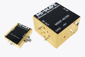
LNAs are built to a defined band, and coverage varies significantly by design. Mi-Wave’s 955 Series, for example, spans Ka-band (26.5-40 GHz), Q-band (33-50 GHz), U-band (40-60 GHz), V-band (50-75 GHz), E-band (60-90 GHz), and W-band (75-110 GHz), with individual models built around a specific waveguide or coaxial interface rather than the full range at once – a 955AF-20/599 Ka-band unit, for instance, covers 26.5-40 GHz over a WR-28 waveguide interface with 20 dB of gain and a 3.5 dB noise figure. Confirm the exact band, and the specific interface, before comparing gain and noise figure numbers across models.
Prioritize Noise Figure Above Gain
Noise figure is usually the single most important number on the datasheet, because it’s the one number a later amplifier stage can never fix. LNAs built for sensitive receivers commonly achieve noise figures below 3 dB, and even a fraction of a dB of difference translates directly into detection range on a radar or link margin on a satellite downlink. Confirm noise figure at your actual operating frequency, not just at the band’s best-case point, since noise figure typically varies across the operating range.
Size Gain Against What’s Downstream, Not in Isolation
Gain in the 955 Series typically runs from 15 to 40 dB depending on model and band, and the right number depends on what has to happen after the LNA, not on maximizing gain for its own sake. Enough gain has to overcome the losses from filters, mixers, switches, and cable or waveguide runs between the LNA and the next active stage; too much gain risks compressing that next stage or degrading the system’s dynamic range. Work the gain budget from the far end of the chain backward rather than picking the highest-gain part on the shelf.
Check Linearity, VSWR, and DC Bias Requirements
A few remaining numbers decide whether the part performs once it’s actually installed:
- Linearity and P1dB: how well the amplifier handles strong nearby signals without compressing or generating intermodulation products, which matters most in crowded RF environments.
- VSWR and Input Matching: proper impedance matching at the input minimizes reflections and directly protects the noise figure the part was chosen for in the first place.
- DC Bias: 955 Series models typically require 6 to 15 V depending on configuration, so confirm your power rail can support the specific model before it’s designed into the board.
Match the LNA to the Application
Satellite downlink and VSAT receivers weigh noise figure and stable gain most heavily, since link margin is fixed by the incoming signal strength. Radar receiver front ends prioritize consistent gain and low noise figure across the full pulse bandwidth to maximize detection sensitivity. Point-to-point microwave and millimeter-wave links depend on the LNA to preserve margin over long paths and variable weather conditions. 5G FR2 development and test platforms need stable gain and low noise for accurate EVM and receiver characterization work.
Common Selection Mistakes to Avoid
- Specifying gain as the primary criterion and treating noise figure as secondary, when it’s almost always the reverse that determines receiver performance.
- Ignoring insertion loss in the filter, switch, or waveguide run ahead of the LNA, which adds directly to system noise figure no matter how good the amplifier itself is.
- Assuming noise figure is flat across the band, rather than checking it holds up at the specific frequency the system actually operates at.
- Overlooking DC bias and mechanical packaging requirements until after the receiver front end is already laid out.
Where This Kind of Component Comes From
Low noise amplifiers for microwave and millimeter-wave bands are built by a relatively small number of specialized manufacturers, since achieving sub-3 dB noise figures at frequencies up to and beyond 100 GHz requires dedicated device selection and matching-network design. Mi-Wave is one of the manufacturers producing this class of hardware, alongside a broader catalog of waveguide and millimeter-wave components for radar, satellite, and defense-oriented receiver systems.
Conclusion
Choosing a microwave low noise amplifier isn’t about picking the highest gain number off a datasheet comparison. It’s about confirming the frequency band and interface, prioritizing noise figure at your actual operating point, sizing gain against the losses downstream, and checking that linearity, VSWR, and DC bias requirements fit your system. Get those fundamentals right, and the LNA stops being the ceiling on your receiver’s sensitivity and becomes the foundation the rest of the chain can build on.
If you’re specifying an LNA for a demanding noise figure or frequency requirement and want to work through the numbers before committing to a part, Contact Us and our engineering team can help match a configuration to your system.
