
How to Choose a Ka-Band Antenna
Two antennas with identical gain numbers on their datasheets can produce completely different results in the field, and the gap almost never shows up until the system is already deployed and the link margin doesn’t add up.
That gap usually traces back to specs that don’t make it onto a one-line comparison chart – beamwidth, polarization purity, sidelobe behavior, and how the antenna is actually fed. Choosing the right antenna for Ka-band work means going past gain and frequency range and checking the handful of numbers that actually predict how it performs once it’s mounted, aligned, and running.
What Sets Ka-Band Antennas Apart
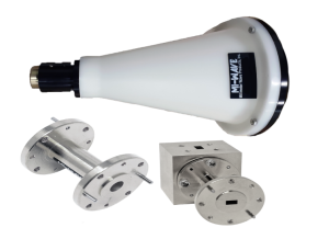
Ka-band covers roughly 26.5 to 40 GHz, a range wide enough to carry satellite communications, radar, and point-to-point links, but narrow enough in wavelength that mechanical tolerances start to matter as much as electrical design. At these frequencies, a horn’s internal machining tolerance, a reflector’s surface accuracy, or a feed’s alignment can shift performance by a decibel or more – tolerances that would be irrelevant at lower frequencies become the difference between a system that closes its link budget and one that doesn’t. Several antenna types cover this band: standard gain horns for calibration and reference use, conical and scalar feed horns for smooth radiation patterns, horn lens antennas for higher gain in a compact package, and reflector-fed systems for the highest gain requirements. A ka band antenna selected for calibration work and one selected for a live radar front end can look identical on a datasheet and still be the wrong choice for each other’s job.
Antenna type narrows the field. The specs that decide whether a specific model fits your system come next.
Start With Gain, Frequency Range, and Beamwidth
Confirm the antenna’s gain is quoted across the full band you’ll use, not just at a single frequency point – gain typically varies by a decibel or more between band edge and midband, and a spec sheet quoting only the best-case number can overstate real performance. Beamwidth and gain move together: a higher-gain horn or reflector concentrates energy into a narrower beam, which improves range and rejection of off-axis interference but makes alignment and pointing accuracy more critical. When gain, frequency coverage, and beamwidth all line up with your platform’s pointing accuracy, a ka band antenna delivers the range performance the datasheet promises without hidden surprises in the field.
Gain and beamwidth describe how tightly the antenna focuses energy. Polarization and impedance match describe how efficiently that energy actually gets used.
Check Polarization and VSWR
A few specs decide whether the antenna’s rated gain actually shows up at the receiver:
- Polarization: confirm linear, circular, or dual-polarized operation matches your system – a polarization mismatch between antenna and receiver can cost several decibels of usable signal for no obvious reason on paper.
- VSWR: reflects how well the antenna’s waveguide interface is matched to the feedline; a mismatched interface reflects power back toward the source instead of radiating it, and can also destabilize an active feed device upstream.
- Aperture efficiency: higher aperture efficiency means more of the physical antenna size is converting into usable gain, which matters when size or weight is constrained.
Weigh Sidelobe Level and Cross-Polarization
Gain and beamwidth describe the main lobe, but an antenna operating near other RF systems or in a cluttered environment lives or dies by what happens outside that main lobe. Sidelobe level determines how much energy leaks toward directions you’re not aiming at, which matters directly for interference rejection in radar and satcom links sharing spectrum with neighboring systems. Cross-polarization discrimination measures how well the antenna maintains its intended polarization rather than leaking energy into the orthogonal one – a spec that rarely appears on a one-page summary but shows up immediately as unexplained signal loss in a dual-polarized system. Neither number moves the needle in a quiet lab test, but both become the first thing to check when a fielded system underperforms its link budget for no apparent reason.
With the electrical performance confirmed, the mechanical interface is what determines whether the antenna actually mounts and mates the way your system expects.
Confirm Waveguide Interface and Mechanical Fit
Ka-band antennas typically interface through WR-28 waveguide with a standard flange, though probe and dual-polarized variants may use different connector arrangements. Confirm the flange type matches your existing waveguide run before ordering, and check the antenna’s mounting footprint and weight against whatever fixture or gimbal it needs to sit on – an antenna with excellent electrical specs is still the wrong choice if it doesn’t physically fit the platform. Manufacturing tolerance matters here too: close dimensional control on the horn or reflector surface is what keeps the antenna’s actual far-field pattern matching its datasheet plot rather than drifting from unit to unit.
Even after the specs check out, a few recurring mistakes account for most of the antenna-related rework in Ka-band system design.
Common Selection Mistakes to Avoid
- Comparing gain figures from different manufacturers without confirming they were measured under the same conditions and frequency point.
- Choosing the highest-gain option available without checking whether the resulting beamwidth is actually usable for the pointing accuracy the platform can achieve.
- Overlooking polarization matching between the antenna and the rest of the RF chain.
- Ignoring mounting weight and footprint until late in mechanical integration, when a ka band antenna with the right electrical specs turns out to be the wrong physical fit.
Where This Kind of Component Comes From
Antennas built for defined waveguide bands like this come from manufacturers running in-house horn machining and far-field pattern testing, since gain and pattern accuracy depend directly on dimensional control during fabrication. Mi-Wave is one of the manufacturers producing this class of hardware, with antenna types spanning horn, reflector, lens, and probe designs across a broad millimeter-wave frequency range.
Conclusion
Choosing the right antenna for Ka-band work means treating gain, beamwidth, polarization, and VSWR as a connected set of trade-offs rather than picking the highest number on a single spec, then confirming the mechanical interface and mounting fit before committing to a platform. Antennas that get this matching right perform close to their datasheet numbers once deployed; ones that don’t become the hardest problem to diagnose in a finished system, because the antenna is rarely the first place engineers look when a link budget comes up short.
