
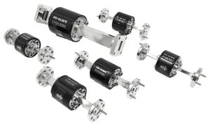
How to Choose a High Power Waveguide Isolator
Most high-power microwave and mm-wave systems don’t lose an amplifier because it was underspecified. They lose it because energy came back. A damaged antenna, a loose connector, or a load that drifts off its design impedance sends power toward the output stage, and the amplifier ends up absorbing what it was never built to take.
An isolator is the component that stands in that path. Choosing one that is simply rated for the right band isn’t enough once real transmit power and mismatched loads enter the picture, and that is where most selection mistakes happen.
What a High Power Waveguide Isolator Actually Does
A high power waveguide isolator is a passive, non-reciprocal two-port device. Power passes from input to output with low loss, while energy traveling the other way is absorbed instead of returned. Ferrite material and a permanent magnetic bias create that one-way behavior, so no external power or control electronics are needed.
What separates a high power version from a general-purpose one is what happens to the reverse energy. It is dissipated as heat in an internal absorptive load, and the design has to handle that heat without shifting the ferrite’s behavior or degrading performance over the system’s life.
Start With Your Frequency Band and Waveguide Size
Isolators are built around a defined operating band and a matching waveguide interface, not a single center frequency. Mi-Wave’s isolator range spans roughly 18 GHz to 325 GHz, and broadband performance applies to select designs rather than every part. Confirm the exact band your system uses, match it to the standard waveguide size, and check performance across the full band, since isolation and VSWR can both soften near the edges of a rated range.
Size for Reflected Power and Duty Cycle, Not Just Forward Power
Forward power sets a baseline, but it rarely decides whether the part survives. The figure that stresses an isolator is the reflected power it must absorb when the load is mismatched, disconnected, or damaged, and that depends on worst-case VSWR rather than the matched-load condition shown on most datasheets.
Duty cycle matters just as much. A pulsed radar and a continuous-wave SatCom uplink put very different thermal loads on the internal termination, even at the same peak power. Since absorbed energy becomes heat, also look at the mounting surface, airflow, and ambient temperature around the isolator.
Power handling varies by band and construction, so confirm figures against your worst-case conditions directly with the manufacturer’s engineering team instead of assuming them from a general specification.
Check Isolation, Insertion Loss, and VSWR
Three numbers do most of the work in predicting how an isolator will behave once installed:
- Isolation: how well reverse energy is blocked. Higher isolation keeps reflections from reaching the amplifier or source behind the isolator.
- Insertion Loss: how much forward signal is lost passing through. In a high-power chain, every fraction of a decibel costs output power and adds heat to the assembly.
- VSWR: how well each port is impedance-matched. A poor match reflects energy on its own, which undoes part of the protection the isolator is there to provide.
Confirm Waveguide Interface and Flange Compatibility
Waveguide isolators ship with a fixed flange type and orientation, and matching that to your existing run matters as much as matching the band. An adapter adds insertion loss, another VSWR discontinuity, and one more joint that has to carry the power passing through it. Confirm flange type, port spacing, and mounting orientation before ordering, particularly on a retrofit.
Account for the Magnet and the Mounting Environment
The permanent magnet that gives the isolator its direction also means magnetic fields matter at the installation point. As a general practice, keep ferrous hardware and other magnetized parts away from the housing, and avoid placing two isolators so close together that their fields interact. Check the rated operating temperature range as well, since heat from absorbed reflections adds to whatever the environment is already contributing.
Match the Isolator to the Application
Amplifier protection is the most common use, with the isolator placed at the output of a solid-state power amplifier to absorb reflections before they return. Radar and SatCom transmit chains rely on the same arrangement to protect upstream stages from antenna mismatch. Test and measurement setups use isolators to keep a source stable when the device under test reflects, and frequency conversion chains use them to keep reflections from disturbing converters and local oscillators.
Common Selection Mistakes to Avoid
- Sizing to forward power only: and overlooking the reflected power the internal load must absorb in a fault.
- Ignoring duty cycle: by comparing a pulsed rating to a continuous-wave requirement, or the reverse.
- Trusting midband numbers: when the system operates near the edge of the rated band.
- Overlooking thermal path: by mounting the isolator where the absorbed heat has nowhere to go.
- Stacking adapters: ahead of the isolator, then troubleshooting a power budget that was never wrong at the isolator itself.
Where This Kind of Component Comes From
Ferrite isolators are built by a relatively small number of specialized manufacturers, since holding isolation and VSWR across a band takes precision machining, controlled assembly, and careful magnetic design. Mi-Wave is one of them, producing Faraday, compact, and Y-junction isolators alongside a broader catalog of waveguide and millimeter-wave components for radar, satellite, and test applications.
Conclusion
Choosing a high power waveguide isolator isn’t about finding the highest power number on a datasheet. It is about matching the band and waveguide size, sizing for worst-case reflected power and real duty cycle, and confirming that isolation, insertion loss, and VSWR hold across the full band. Get those fundamentals right, along with a flange that drops into your existing run, and the isolator keeps reflections away from the amplifier it protects.
If you are specifying an isolator for a transmit chain and want to work through reflected power, duty cycle, and thermal limits before committing to a part, Contact Us and our engineering team can help match a configuration to your system.