
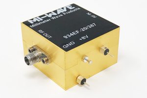
How to Choose a 93X Series Frequency Multiplier
Most millimeter-wave systems don’t fail because the antenna is wrong or the amplifier underperforms – they fail because the signal driving them was never clean enough to begin with, and by the time that shows up on a spectrum analyzer, it’s already too late to trace the problem back to its source.
That signal usually originates several octaves below the frequency it eventually needs to reach. Building a stable oscillator directly at 60, 90, or 140 GHz is difficult and costly, so most designs generate a clean, low-frequency signal and step it up electronically instead. The component responsible for that step-up is the frequency multiplier, and choosing the right one has more influence on system performance than most engineers expect going in.
What a Frequency Multiplier Actually Does
A frequency multiplier is a non-linear device that takes an input signal at frequency f and produces an output at a multiple of it – 2f, 4f, or 6f, depending on the design – while filtering out everything in between. Passive designs rely on non-linear diode behavior and lose signal strength with each stage. Active designs add a gain stage to recover that loss and deliver usable output power directly, which decides whether you’ll need extra amplification downstream. This guide focuses on selecting an active 93X series frequency multiplier for a real system requirement, not on comparing datasheet numbers side by side.
Once the multiplier type is settled, the next decision is where in the spectrum it needs to operate, and that’s rarely as simple as picking a single center frequency.
Start With Your Input and Output Frequency Range
Every multiplier is designed around a defined input band and a corresponding output band, tied to a standard waveguide size – WR-42, WR-28, WR-22, WR-15, WR-12, WR-10, and so on. Confirm the exact frequency range your system needs and match it to a waveguide-band-compatible unit. Multipliers spanning roughly 9-18 GHz on the input side and reaching anywhere from 18 GHz up into W-band on the output are common, but coverage varies by model, and a unit rated for one waveguide band won’t hold spec outside it. Getting this wrong is the single most common reason a multiplier underperforms after installation – not a manufacturing defect, just a mismatch between the part and the application.
With the band settled, the next question is how much multiplication you actually need to get there.
Match the Multiplication Factor to Your System
Frequency multipliers typically ship in x2, x4, x6, and x8 configurations, and the right factor depends entirely on what source frequency you already have available. A lower multiplication factor generally preserves phase noise performance better, since each doubling stage adds roughly 6 dB of phase noise degradation relative to the input. If your existing source frequency and target output line up with a standard factor, a 93x frequency multiplier is usually the simplest and most cost-effective path to the frequency you need, rather than redesigning the source itself. Jumping to a higher multiplication factor just to avoid redesigning an oscillator can look easier on paper, but it often trades that convenience for phase noise you can’t recover later.
Frequency range and multiplication factor narrow the field quickly, but the numbers that decide whether a specific unit performs in your chain come next.
Check Input Drive Level and Output Power
Multipliers have a defined input drive range, and both under-driving and over-driving it hurt performance. Too little input power and the multiplier won’t generate a clean, saturated output; too much and you risk damaging the diode elements or pushing spurious harmonics higher. Confirm the input power your source can reliably deliver – typically a few milliwatts up to around 15 dBm for active designs – and check it falls inside the specified drive window, not just above the minimum threshold. On the output side, compare rated output power against what your next stage needs, factoring in cable or waveguide run loss between the two.
Power numbers tell you whether the signal will be usable. Purity numbers tell you whether it stays usable.
Look at VSWR and Harmonic Suppression
A few datasheet numbers do more to predict real-world performance than the rest combined:
- VSWR: reflects how well each port is impedance-matched; a mismatched port reflects energy back into the chain and can degrade both source and load. 2.00:1 or better is a reasonable working target for most systems.
- Harmonic suppression: measures how well unwanted harmonics are filtered out next to the one you actually want; look for at least -20 dBc of suppression on the nearest unwanted harmonic.
- Supply voltage and current draw: active designs need a DC bias, typically in the 8-12V range, so confirm your power rail can support it without adding a separate regulator.
Once the electrical specs check out, the physical interface is what determines whether the part actually drops into your build.
Confirm Connector and Interface Compatibility
Input connections are usually SMA or K-type female, while the output is almost always a waveguide interface matched to the operating band, though some models also accept a waveguide input for U, V, E, and W-band configurations. Confirm the flange type on the output side lines up with your existing waveguide run before ordering – a mismatched flange means an adapter, and every adapter in the chain adds insertion loss and another point of potential VSWR degradation. It’s a five-minute check that avoids weeks of delay if it’s missed.
With the electrical and mechanical fit confirmed, it’s worth stepping back and matching the part to what the system is actually being used for.
Match the Multiplier to the Application
Active multipliers show up most often as LO sources feeding a mixer, as frequency extenders letting a lower-band signal generator reach mm-wave ranges it can’t natively produce, and in test setups where a stable, known reference is needed at a specific frequency. Each use case weighs the specs differently: an LO chain cares most about phase noise, a frequency extender cares most about output power reaching the next stage, and a test bench often prioritizes flatness and repeatability. For LO generation, signal extension, and bench work at frequencies a standard synthesizer can’t reach directly, a 93x frequency multiplier removes the need for a dedicated high-frequency source altogether.
Even with every spec lined up, a handful of recurring mistakes account for most of the re-designs and return requests on this class of component.
Common Selection Mistakes to Avoid
- Specifying by center frequency only, without confirming the unit holds spec across the full band edge-to-edge, not just at midband.
- Choosing the highest available multiplication factor by default, rather than the lowest factor that reaches the target frequency.
- Overlooking DC bias and current requirements until after the board is already laid out.
- Ignoring insertion loss from cables, adapters, and waveguide runs between the multiplier and the next stage, then wondering why output power reads low at the bench.
Where This Kind of Component Comes From
Active multiplier lines like this are built by a small number of specialized millimeter-wave manufacturers rather than general RF component suppliers, since the diode design and waveguide integration require dedicated process control. Mi-Wave is one of the manufacturers producing this class of hardware, alongside a broader catalog of waveguide and mm-wave components for defense, aerospace, and test applications.
Conclusion
Selecting the right multiplier isn’t about picking the highest-spec part off a comparison chart – it’s about matching frequency range, multiplication factor, drive level, and interface to what your system genuinely needs. Get the band and factor right, confirm the power and purity numbers hold up under your actual operating conditions, and check the physical interface before committing to a design. Do that groundwork upfront, and the multiplier stops being a variable you have to troubleshoot later and becomes a fixed, reliable link in the signal chain.
