

RF Orthomode Transducers OMT
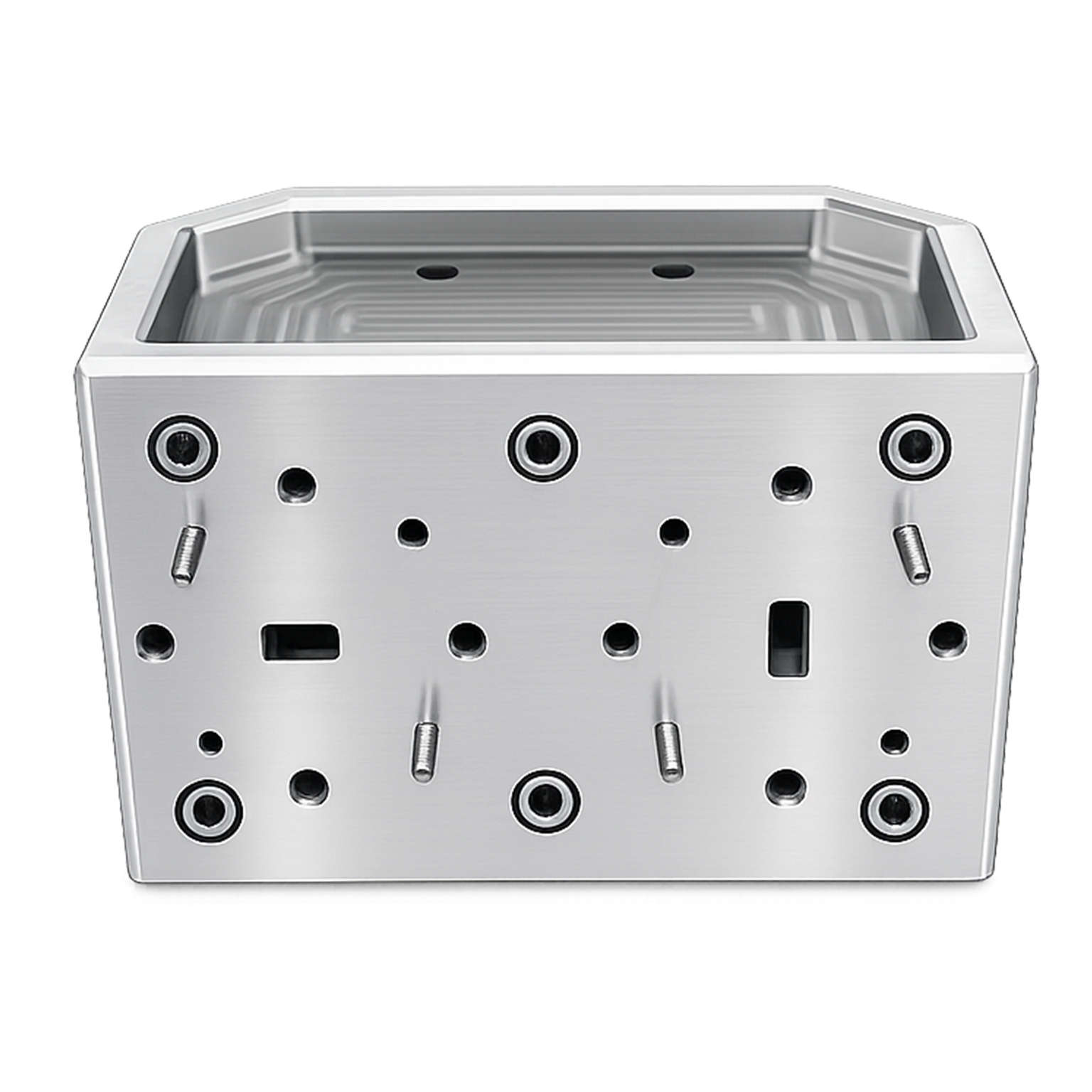
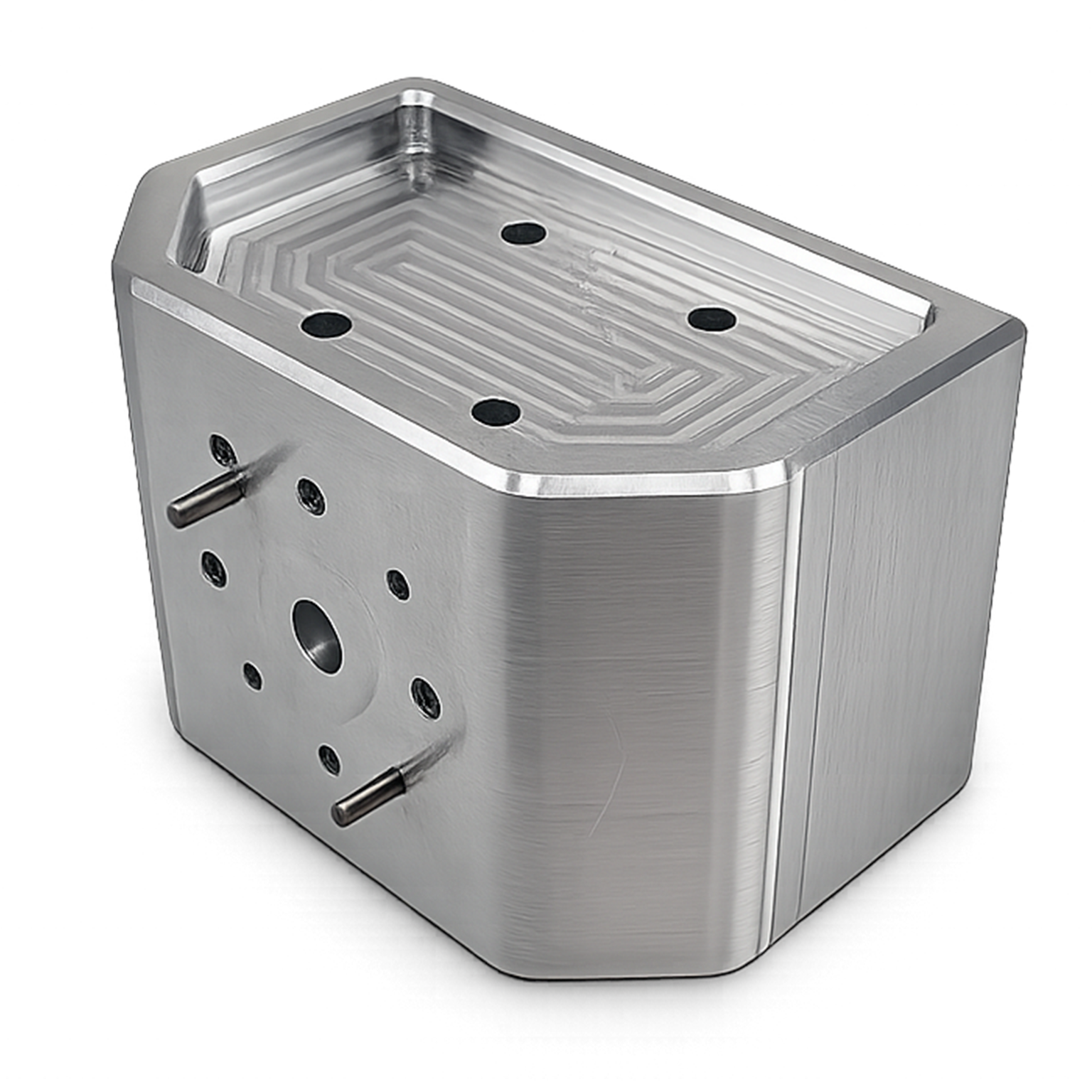
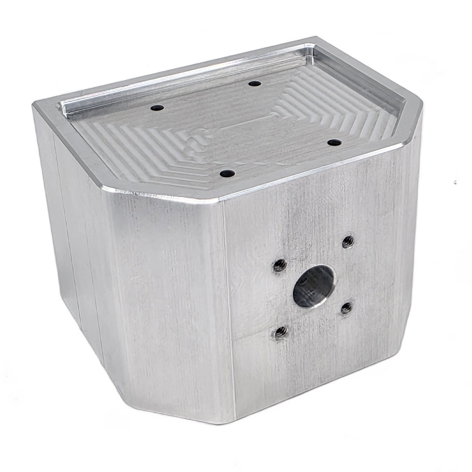
Mi-Wave’s 281 Series Orthomode Transducers (OMTs) are precision waveguide components designed to simultaneously couple and separate two orthogonal linearly polarized RF signals while maintaining high isolation between channels. These devices are widely used in microwave and millimeter-wave systems where dual-polarization operation, low insertion loss, and reliable signal separation are critical.
OMTs are essential in systems that must transmit and receive independent polarized signals through a common waveguide path. By providing strong polarization isolation, the 281 Series helps minimize cross-coupling and preserve signal integrity in advanced RF architectures. This makes them especially valuable in radiometers, dual-polarized antennas, satellite communication systems, radar platforms, and high-frequency instrumentation.
Available across frequency ranges from 12.4 GHz to 220 GHz with 3% or greater bandwidth, Mi-Wave’s 281 Series supports broadband microwave and millimeter-wave applications requiring stable RF performance and compact waveguide integration.
Explore Mi-Wave’s complete range of dual-polarized antenna solutions engineered for RF, microwave, and millimeter-wave applications. Many configurations are compatible with Mi-Wave Orthomode Transducers (OMTs), supporting Vertical and Horizontal polarization paths, high isolation, and efficient antenna system integration.
The standard models shown represent only part of Mi-Wave’s broader product capabilities. Custom configurations are available to support specific frequency bands, interfaces, and application requirements, enabling optimized solutions for specialized RF, microwave, and millimeter-wave systems.
Note: Our website contains just a few types of Orthomode Transducers we build. Consult with us for your specific needs.
| Model/Flange | Band | Circular Antenna Port Internal Diameter (inches)(.XXX in Model No.) | Frequency (GHz) | Flange | Bandwidth (GHz) | Isolation (H to V)(dB) | Cross Polarization (Port) | LINK |
|---|---|---|---|---|---|---|---|---|
| 281X-XX/.XXX | X-Band | Option 1 1.094" ID Circular Waveguide Option 2 .938" ID Circular Waveguide Option 3 .797" ID Circular Waveguide | 8-9.97 8.5-11.6 9.7-12.4 | UG-90/U | 1.5 | 35 | (H to A): 30 (V to A): 30 | |
| 281Ku-XX/.XXX/419 | Ku-Band | Option 1 .660" ID Circular Waveguide Option 2 .550" ID Circular Waveguide | 12.4-14.6 14.6-17.5 | UG-419/U | 2 | 35 | (H to A): 30 (V to A): 30 | |
| 281K-XX/.XXX/595 | K-Band | Option 1 .470" ID Circular Waveguide Option 2 .396" ID Circular Waveguide Option 3 .328" ID Circular Waveguide | 17.5- 20.5 20.5-24.5 24.5-26.5 | UG-595/U | 3 | 35 | (H to A): 30 (V to A): 30 | |
| 281(34)-XX/.XXX/595 | WR-34 | .396" ID Circular Waveguide | 18.5-31 | UG-595/U | 12.5 | 40 | (H to A): 30 (V to A): 30 | |
| 281A-XX/.XXX/599 | Ka-Band | .281" ID Circular Waveguide | 26.5-40 | UG-599/U | 5.5 | 30 | (H to A): 30 (V to A): 30 | |
| 281(22)-XX/.XXX/383 | WR-22 | .219" ID Circular Waveguide | 33-55 | UG-383/U | 22 | 40 | (H to A): 30 (V to A): 30 | |
| 281B-XX/.XXX/383 | Q-Band | Option 1 .281" ID Circular Waveguide Option 2 .250" ID Circular Waveguide Option 3 .188" ID Circular Waveguide | 33.0-38.5 38.5-43.0 43.0-50.0 | UG-383/U | 4 | 30 | (H to A): 30 (V to A): 30 | |
| 281U-XX/.XXX/383 | U-Band | Option 1 .328" ID Circular Waveguide Option 2 .281" ID Circular Waveguide Option 3 .250" ID Circular Waveguide Option 4 .219" ID Circular Waveguide | 40-43 43-50 50-58 58-60 | UG-383/U-M | 5 | 30 | (H to A): 30 (V to A): 30 | |
| 281V-XX/.XXX/385 | V-Band | Option 1 .165" ID Circular Waveguide Option 2 .141" ID Circular Waveguide Option 3 .125" ID Circular Waveguide | 50-58 58-68 68-75 | UG-385/U | 5 | 30 | (H to A): 30 (V to A): 30 | |
| 281E-XX/.XXX/387 | E-Band | Option 1 .141" ID Circular Waveguide Option 2 .125" ID Circular Waveguide Option 3 .110" ID Circular Waveguide (77-87 GHz) Option 4 .094" ID Circular Waveguide (87-90 GHz) | 60-68 68-77 77-87 87-90 | UG-387/U | 6 | 30 | (H to A): 30 (V to A): 30 | |
| 281W-XX/.XXX/387 | W-Band | Option 1 .125" ID Circular Waveguide Option 2 .110" ID Circular Waveguide Option 3 .094" ID Circular Waveguide (87-100 GHz) Option 4 .082" ID Circular Waveguide (100-110 GHz) | 75-77 77-87 87-100 100-110 | UG-387/U-M | 6 | 30 | (H to A): 30 (V to A): 30 | |
| 281F-XX/.XXX/387 | F-Band | Option 1 .094" ID Circular Waveguide Option 2 .082" ID Circular Waveguide Option 3 .075" ID Circular Waveguide Option 4 .067" ID Circular Waveguide | 90-100 100-112 112-125 125-140 | UG-387/U-M | 6 | 25 | (H to A): 25 (V to A): 25 | |
| 281D-XX/.XXX/387 | D-Band | Option 1 .082" ID Circular Waveguide Option 2 .075" ID Circular Waveguide Option 3 .067" ID Circular Waveguide Option 4 .059" ID Circular Waveguide | 110-112 112-125 125-160 160-170 | UG-387/U-M | 7 | 25 | (H to A): 25 (V to A): 25 | |
| 281G-XX/.XXX/387 | G-Band | Option 1 .067" ID Circular Waveguide Option 2 .059" ID Circular Waveguide | 125-140 140-220 | UG-387/U-M | 7 | 20 | (H to A): 20 (V to A): 20 |
Your Content Goes Here
Features & Specifications
Mi-Wave’s 281 Series Orthomode Transducers are engineered to provide efficient polarization separation and dependable RF performance across microwave and millimeter-wave systems.
Dual Orthogonal Polarization Operation
Couples and separates two orthogonal linearly polarized signals simultaneously within a common waveguide structure.
Broad Frequency Coverage
Available from 12.4 GHz to 220 GHz, supporting a wide range of microwave and millimeter-wave applications.
Full Bandwidth Availability
Designed to support full-band operation within standard waveguide frequency ranges.
Typical VSWR: 1.2:1
Provides good impedance matching to reduce reflections and help preserve signal quality.
Typical Isolation: Greater Than 30 dB
Maintains strong polarization separation between channels to reduce interference and improve system performance.
Low Insertion Loss
Helps preserve RF signal strength and improve overall link efficiency.
Broadband Operation
Suitable for systems requiring wider operational bandwidth and stable electrical performance.
Higher Frequency Units Available on Request
Additional high-frequency solutions can be quoted for specialized applications.
Precision Waveguide Construction
Designed for reliable integration into antenna feeds, RF front ends, and measurement systems.
How Orthomode Transducers Work
Orthomode Transducers (OMTs) operate by separating or combining two orthogonal electromagnetic field components within a single waveguide structure. These components correspond to two independent linear polarizations, typically oriented 90 degrees apart.
In a standard rectangular waveguide, the dominant propagation mode is TE₁₀, where the electric field is oriented along one axis. An OMT is designed to extract or inject signals aligned with two orthogonal field orientations, enabling dual-channel operation within the same physical transmission path.
Field Separation Mechanism
Inside an OMT, the incoming electromagnetic wave contains field components aligned along two perpendicular axes. The structure uses precision-engineered junctions, probes, or waveguide transitions to selectively couple energy from each polarization into separate output ports.
- One port is aligned to capture the horizontal (or X-axis) polarization
- The other port captures the vertical (or Y-axis) polarization
This separation is achieved without mechanical switching, relying entirely on the geometry and electromagnetic symmetry of the structure.
Polarization Isolation
High isolation between ports is achieved through careful control of:
- Waveguide symmetry
- Probe placement or coupling apertures
- Impedance matching across both polarization paths
Because each port is only sensitive to its corresponding field orientation, signals in one polarization are largely rejected by the orthogonal port. This results in isolation levels typically greater than 30–40 dB, minimizing cross-coupling and preserving signal integrity.
Dual-Polarized Signal Operation
OMTs enable two independent RF signals to share the same waveguide by assigning each to a different polarization. This allows systems to:
- Transmit and receive simultaneously
- Double channel capacity using polarization multiplexing
- Maintain compact RF front-end architectures
In receive mode, the OMT separates incoming signals into two independent paths. In transmit mode, it combines two signals into a single waveguide output while preserving polarization separation.
Broadband Performance Considerations
To support wideband operation, OMT designs must maintain consistent performance across frequency. This requires:
- Stable impedance matching (low VSWR)
- Minimal variation in insertion loss
- Consistent phase and amplitude balance
- Suppression of higher-order modes
Broadband OMTs are engineered to operate across the full waveguide band, ensuring reliable performance in systems with wide frequency requirements.
Integration in RF Systems
OMTs are typically located at the antenna feed interface, where they connect directly to feed horns or reflector systems. From there, each polarization path feeds into separate RF chains, which may include:
- Low Noise Amplifiers (LNAs) for receive paths
- Power Amplifiers (PAs) for transmit paths
- Frequency converters (up/downconverters)
- Filters and signal conditioning components
This architecture allows efficient use of physical space while maintaining high-performance signal separation.
Why OMTs Matter
By enabling dual-polarized operation in a single waveguide, OMTs play a critical role in modern RF systems:
- Increase spectral efficiency
- Reduce system size and complexity
- Improve signal isolation and quality
- Support high-capacity Satcom and radar systems
Their passive, highly reliable design makes them essential components in both microwave and millimeter-wave architectures.
Applications
Mi-Wave’s 281 Series Orthomode Transducers are used in RF systems requiring dual-polarization signal separation, low loss, and reliable isolation.
Satellite Data Transmission
Supports dual-polarized communication architectures used in satellite uplinks, downlinks, and broadband data systems.
Satellite Television Broadcasting
Used in satellite broadcast systems where polarization separation and low insertion loss are important.
Military Radar Systems
Enables polarization diversity and signal separation in radar platforms operating at microwave and millimeter-wave frequencies.
Telecommunications Antennas
Integrates into antenna feed systems for point-to-point and high-capacity communication links.
Sensors
Supports RF sensing systems that require dual-polarized or multi-channel signal handling.
Radiometers
Used in radiometric systems for measurement and separation of orthogonal signal components.
Instrumentation
Well suited for laboratory and test systems requiring accurate polarization control and broadband RF performance.
Frequently Asked Questions (FAQ)
What is an Orthomode Transducer?
An Orthomode Transducer, or OMT, is a waveguide component that separates or combines two orthogonal linearly polarized signals within a single waveguide system.
What is the purpose of an OMT?
An OMT allows two independent polarized signals to share a common waveguide path while maintaining isolation between them. This helps improve bandwidth efficiency and supports dual-channel RF operation.
What frequency range does the 281 Series support?
The 281 Series is available from 12.4 GHz to 220 GHz, depending on waveguide band and model.
What is the typical isolation of the 281 Series?
Typical isolation is greater than 30 dB, helping reduce cross-coupling between polarization channels.
What is the typical VSWR of the 281 Series?
Typical VSWR is approximately 1.2:1, supporting good impedance matching and low reflected power.
What applications use OMTs?
OMTs are commonly used in satellite communications, radar systems, telecommunications antennas, radiometers, sensors, and test instrumentation.
Can an OMT be used as a diplexer?
In some communication link architectures, an OMT can be used in a diplexer-like role by separating orthogonal polarized signals within the same waveguide system.
Why is low insertion loss important in an OMT?
Low insertion loss helps preserve system gain, improve signal strength, and maintain overall RF link performance.
OMT & Waveguide Calculators
These calculators help estimate key RF parameters for orthomode transducers, including wavelength, return loss to VSWR conversion, and isolation-based leakage power. Useful for Satcom, antenna feeds, and dual-polarized RF systems.
Wavelength Calculator
Calculate wavelength from frequency for waveguide and RF systems.
Return Loss → VSWR
Convert return loss to VSWR for impedance matching evaluation.
Isolation Leakage Calculator
Estimate leakage power between polarization ports based on isolation.
Interested in this product or other Mi-Wave solutions?
Contact our team to discuss your frequency range, interface needs, and application requirements.
Custom configurations are available for specialized RF, microwave, and millimeter-wave systems.
Return to Antennas
Return to Products Page