

900WF-30/387 – WR-10 W-Band Voltage Controlled Attenuator
The 900WF-30/387 is a WR-10 waveguide, W-Band PIN diode voltage controlled attenuator operating from 75 GHz to 110 GHz. Designed for microwave and millimeter-wave applications, this reflective attenuator provides a 30 dB attenuation range with stable RF performance, low insertion loss, and high isolation across the W-Band frequency range.
Description
Mi-Wave’s 900 Series W-Band PIN Diode Attenuators combine low insertion loss, high isolation, and compact mechanical design for integration into high-frequency RF and millimeter-wave systems.
The 900WF-30/387 reflective attenuator provides continuous analog attenuation control using PIN diode technology. Attenuation is controlled via an external bias voltage, enabling smooth RF level adjustment without mechanical switching.
Isolation-enhanced configurations are available up to 60 dB, depending on system requirements.
Typical Applications
-
W-Band signal level control
-
Receiver protection
-
Signal switching
-
Automatic level control (ALC)
-
Millimeter-wave test and measurement systems
-
High-frequency radar and communication architectures
Customization & Engineering Support
Mi-Wave designs and manufactures both standard and custom voltage-controlled attenuators for microwave and millimeter-wave systems. Frequency coverage, attenuation range, isolation level, and mechanical configuration can be tailored to meet specific application requirements.
Contact Mi-Wave to discuss your WR-10 W-Band voltage controlled attenuator requirements or custom specifications.
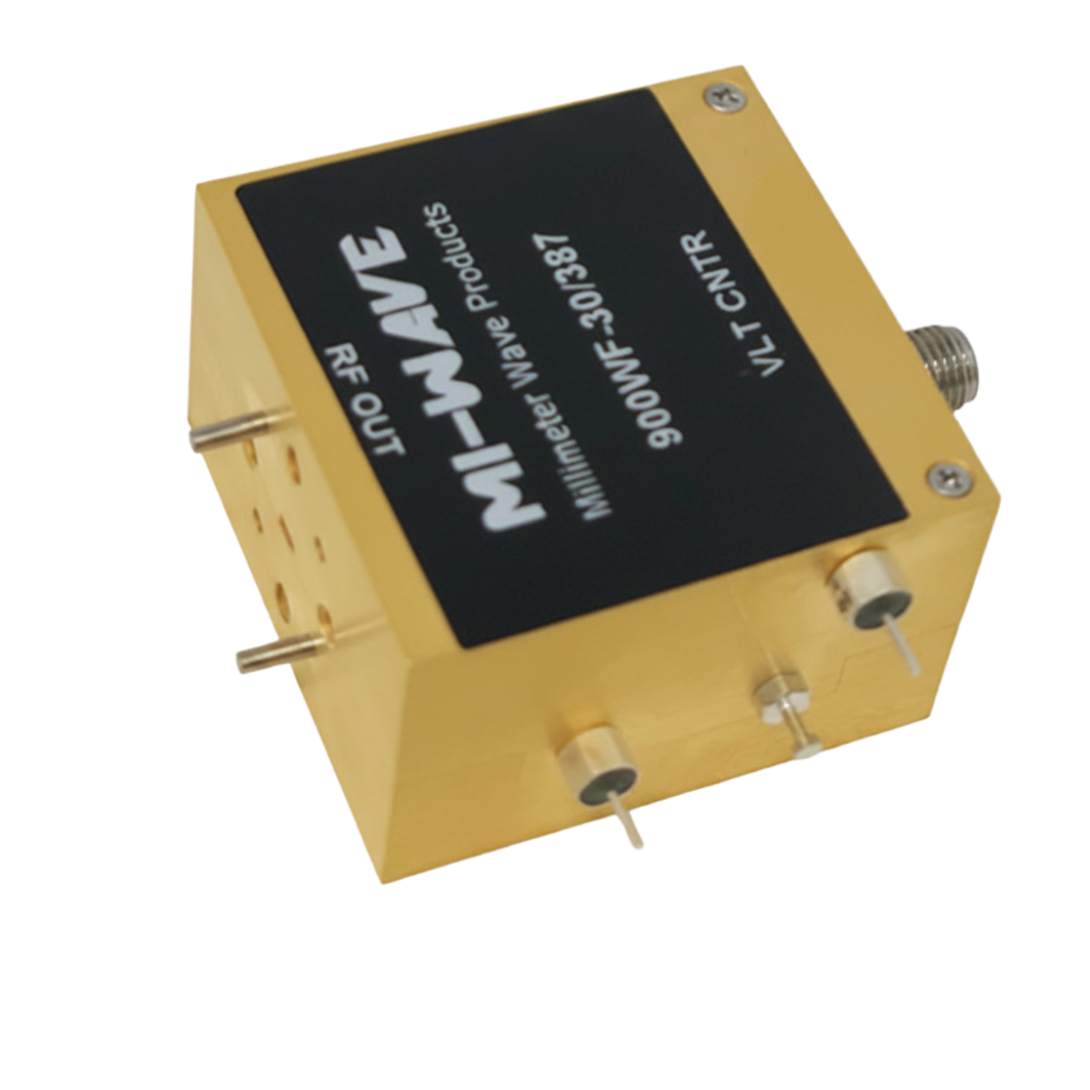
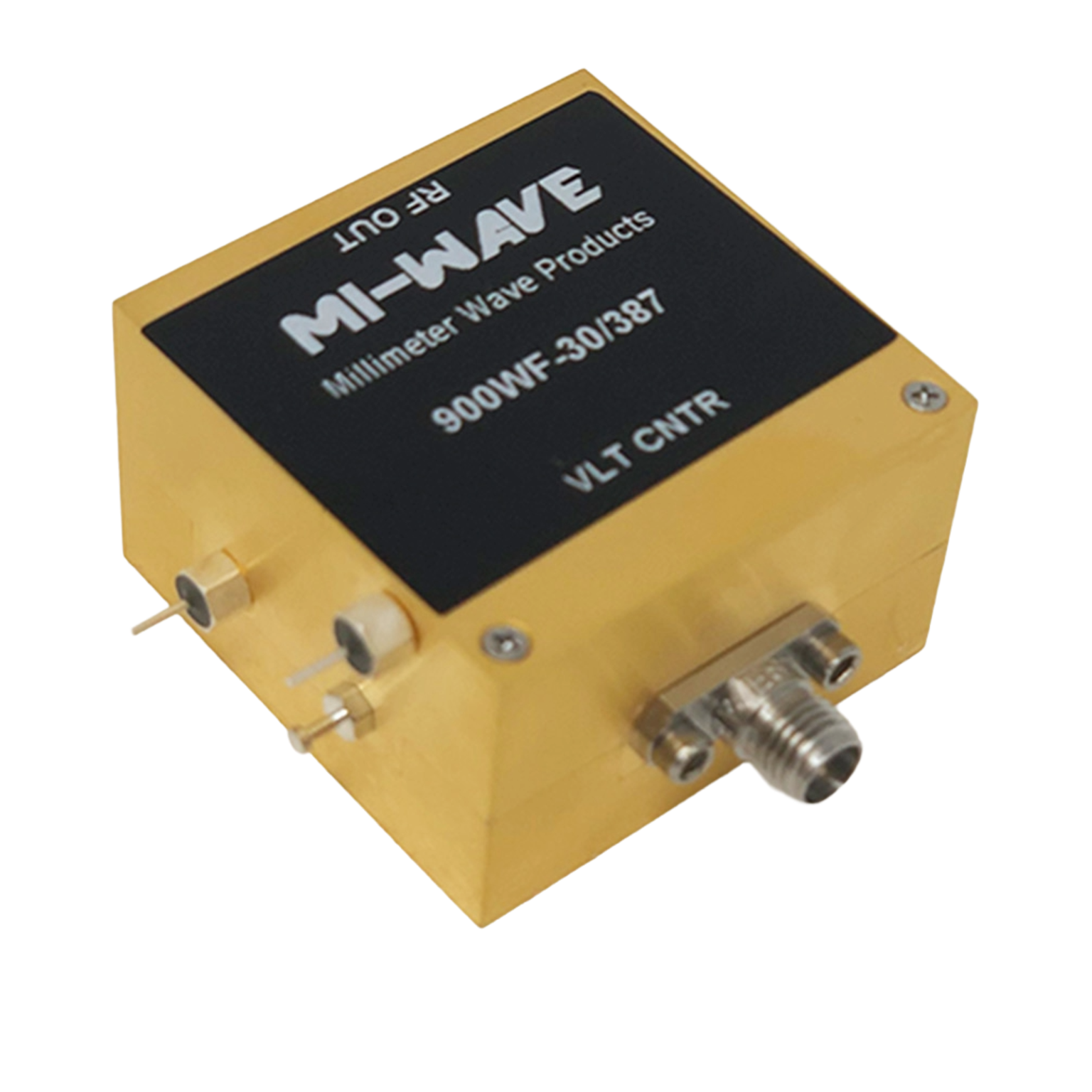
*Actual product may be different from the image shown per customers specifcations
*All data presented is collected from a sample lot.
* Actual data may vary unit to unit, slightly.
*All testing was performed under +25 °C case temperature.
*Consult factory to confirm if material, plating, size, shape, orientation and any electrical parameter is critical for the application as website information is for reference only.
*Millimeter Wave Products, Inc. reserves the right to change the information presented on website without notice as we continue to enhance the performance and design of our products.
Key Specifications
General
Model Number: 900WF-30/387
Frequency Band: W-Band
Frequency Range: 75 GHz – 110 GHz
Electrical Specifications
Frequency: 75 GHz – 110 GHz
Attenuation Range: 0 dB – 30 dB
Power Handling: 20 dBm
Bias Voltage: +8 Volts
Bias Current: 250 mA
Attenuation Control Voltage: 0 – 10 Volts
Attenuator Type: Reflective PIN Diode
Isolation Options: Up to 60 dB (configuration dependent)
Mechanical Specifications
Waveguide Interface: WR-10
Mechanical Configuration: Waveguide Package (WR-10)
Attenuator Calculators
These calculators support RF level planning, receiver protection, path-loss simulation, cascaded attenuation planning, and quick power conversion checks for RF, microwave, and millimeter-wave test chains.
Output Level
Compute output power after attenuation and estimate dissipated power in the attenuator.
Required Attenuation
Determine the attenuation needed to reach a target output level.
Cascaded Attenuation
Add multiple attenuators in series. Enter values separated by commas.
Attenuation to Power Ratio
Convert attenuation (dB) to power ratio (Pout / Pin).
Attenuation to Voltage Ratio
Convert attenuation (dB) to voltage ratio (Vout / Vin) in impedance-matched systems.
dBm ↔ W
Quick conversions for RF power levels.
Key Features & Performance Benefits
Mi-Wave PIN diode voltage variable attenuators are engineered to deliver smooth, repeatable attenuation control and stable RF performance across microwave and millimeter-wave frequency bands. These devices are optimized for dynamic signal conditioning applications where impedance match, attenuation flatness, and predictable control response are critical.
Key Features
-
Continuous voltage-controlled attenuation for precise, real-time level adjustment
-
PIN diode topology enables fast response without mechanical switching or wear
-
Microwave through millimeter-wave coverage including Ka-, Q-, V-, and W-Band options (model dependent)
-
Low VSWR and strong impedance matching to minimize reflections in high-frequency signal chains
-
Stable attenuation performance vs. frequency to reduce measurement error and improve repeatability
-
Waveguide and coaxial configurations available for system integration and test environments
-
Designed for automated control in ALC loops, gain control, and receiver protection circuits
-
Custom configurations available for frequency band, attenuation range, control characteristics, and mechanical packaging
Performance Benefits
-
Improved receiver protection and dynamic range by controlling signal levels before sensitive stages
-
Better calibration and test accuracy through repeatable attenuation and reduced mismatch effects
-
Cleaner signal conditioning for modulated and wideband signals where stability matters
-
Faster level control in closed-loop systems supporting ALC, AGC, and adaptive RF chains
-
Reliable integration in lab, rack, and embedded systems with predictable control behavior and robust construction
Applications
Mi-Wave PIN diode voltage variable attenuators are deployed in RF, microwave, and millimeter-wave systems that require continuous, fast, and predictable signal level control. These devices are particularly valuable in applications where attenuation must be dynamically adjusted without mechanical switching and where impedance stability and attenuation flatness directly impact overall system performance.
Satellite Communications (SatCom)
-
Ground station uplink and downlink chains
-
Ka-, Q-, V-, and W-Band payload testing
-
Automatic level control (ALC) in transmit and receive paths
-
Signal conditioning ahead of LNAs and frequency converters
-
Link margin verification and path-loss simulation
Voltage-controlled attenuation enables precise gain management within high-frequency satellite communication architectures, improving receiver protection and signal integrity.
Radar Systems
-
Transmit/receive (T/R) module gain control
-
Receiver front-end protection from high-power pulses
-
Calibration and signal chain balancing
-
Dynamic attenuation in phased-array systems
Fast analog response makes PIN diode attenuators well suited for radar environments where timing, stability, and reliability are critical.
Electronic Warfare (EW) and Defense Systems
-
Signal conditioning and level control
-
Adaptive RF front-end management
-
Test and validation of high-frequency EW subsystems
-
Controlled attenuation in multi-band and wideband architectures
Stable attenuation and low VSWR are essential in EW systems operating across broad frequency ranges.
RF and Microwave Test & Measurement
-
Receiver sensitivity testing
-
Gain compression and linearity evaluation
-
Automated test setups requiring analog control
-
Calibration of signal generators and amplifiers
-
Millimeter-wave laboratory measurements
Continuous voltage control simplifies integration into automated test systems and remote-control environments.
5G and Emerging 6G Millimeter-Wave Research
-
Beamforming and phased-array research
-
mmWave front-end evaluation
-
Signal level management in prototype systems
-
Wireless infrastructure development
High-frequency attenuation control supports the precise signal conditioning required in advanced wireless research platforms.
System-Level Integration
-
Rack-mounted and embedded RF subsystems
-
Aerospace and defense platforms
-
Industrial and scientific research systems
-
Continuous-wave and high-duty-cycle environments
Mi-Wave PIN diode attenuators are designed to integrate cleanly into laboratory, production, and field-deployed RF architectures where predictable attenuation behavior and robust construction are required.
PIN Diode Voltage Variable Attenuator FAQ
These quick answers cover microwave and millimeter-wave PIN diode voltage variable attenuators used in satellite communications (SatCom), radar systems, electronic warfare platforms, 5G/mmWave development, telemetry systems, and RF test and measurement applications.
Quick Answers
A PIN diode voltage variable attenuator adjusts RF signal level continuously by varying the bias voltage applied to the PIN diode. This changes the diode’s RF resistance, enabling precise attenuation control without mechanical switching.
A fixed attenuator provides a constant attenuation value. A voltage variable attenuator allows real-time attenuation adjustment using an analog control voltage, making it suitable for automatic level control and adaptive RF systems.
PIN diode attenuators offer faster response, no mechanical wear, smoother control, and improved integration into automated microwave and millimeter-wave systems.
More Technical Questions
Yes. They are commonly used in Ka-, Q-, V-, and W-Band uplink and downlink chains for gain control, receiver protection, and calibration.
Mi-Wave supports microwave and millimeter-wave bands including X-band, Ku-band, Ka-band, Q-band, V-band, and W-band, depending on configuration.
Increasing bias current lowers RF resistance and reduces attenuation. Decreasing bias current increases RF resistance and raises attenuation. The exact response depends on circuit topology and frequency.
Low VSWR minimizes reflections and mismatch losses, which are especially critical at higher microwave and millimeter-wave frequencies.
Yes. Frequency range, attenuation range, control characteristics, interface type, and mechanical configuration can be customized for specific RF system requirements.
1. PIN Diode & Attenuator Technology
PIN Diode
A semiconductor device with an intrinsic (I) region between P and N layers. In RF and microwave applications, the PIN diode acts as a current-controlled resistor at high frequencies. This property enables continuous attenuation control in voltage variable attenuators used in microwave and millimeter-wave systems.
PIN Diode Attenuator
An RF attenuator that uses one or more PIN diodes to vary attenuation based on applied DC bias current. Commonly used in analog gain control, automatic level control (ALC), and receiver protection circuits.
Voltage Variable Attenuator (VVA)
A continuously adjustable RF attenuator that varies signal level using an analog control voltage. Unlike fixed attenuators or digital step attenuators, VVAs provide smooth, real-time attenuation control.
Fixed Attenuator
An RF attenuator that provides a constant attenuation value in dB. Used for permanent signal level reduction or calibration.
Digital Step Attenuator
An attenuator that provides discrete attenuation steps, typically controlled via digital logic. Unlike PIN diode VVAs, step attenuators do not provide continuous analog control.
Bias Current
The DC current applied to a PIN diode to control its RF resistance. Increasing bias current lowers RF resistance and reduces attenuation; decreasing current increases attenuation.
Control Voltage Range
The allowable DC voltage range used to control attenuation in a voltage variable attenuator. The control voltage determines the usable attenuation range and linearity.
2. Attenuation & RF Performance Terminology
Attenuation (dB)
The reduction in RF signal power expressed in decibels. Attenuation is calculated based on the ratio of input to output power and is fundamental to RF level planning and system protection.
Attenuation Range
The total adjustable attenuation span of a voltage variable attenuator, typically expressed in dB (e.g., 0–20 dB, 0–30 dB).
Attenuation Linearity
The consistency and predictability of attenuation versus control voltage. Good linearity ensures stable gain control in ALC and AGC loops.
Insertion Loss
The minimum signal loss when the attenuator is set to its lowest attenuation state. Lower insertion loss improves system noise performance.
Attenuation Flatness
The variation of attenuation across the operating frequency band. Flat attenuation response is critical in wideband microwave and millimeter-wave systems.
VSWR (Voltage Standing Wave Ratio)
A measure of impedance matching in an RF signal path. Low VSWR in an attenuator reduces reflections and improves system stability at microwave and millimeter-wave frequencies.
Return Loss
The amount of reflected RF power due to impedance mismatch. High return loss indicates good matching.
Power Handling
The maximum RF input power an attenuator can safely dissipate without thermal damage or performance degradation.
Power Dissipation
The RF power converted to heat inside an attenuator. In voltage variable attenuators, dissipation increases as attenuation increases.
Dynamic Range
The usable range between minimum detectable signal and maximum allowable signal before distortion or overload. Proper attenuation improves system dynamic range.
3. System-Level Attenuation Applications
Automatic Level Control (ALC)
A feedback system that adjusts attenuation to maintain a constant RF output level. PIN diode voltage variable attenuators are commonly used in ALC loops in satellite communication transmit chains.
Automatic Gain Control (AGC)
A system that automatically adjusts gain or attenuation to stabilize received signal amplitude in RF and microwave receivers.
Receiver Protection
The use of RF attenuation to prevent excessive signal power from damaging low-noise amplifiers (LNAs) or sensitive front-end components.
Gain Control Loop
A closed-loop system using voltage variable attenuators or amplifiers to regulate signal amplitude within a transmit or receive chain.
Signal Conditioning
The process of adjusting signal level, impedance, or spectral characteristics within an RF signal chain to optimize system performance.
Link Budget
A system-level calculation used in satellite communications and microwave links to determine required attenuation, transmit power, antenna gain, and path loss to achieve reliable communication.
4. Frequency & Interface Terminology
Microwave Frequencies
Typically 1 GHz to 30 GHz. Common bands include X-band, Ku-band, and Ka-band.
Millimeter-Wave Frequencies
Frequencies above 30 GHz, including Ka-, Q-, V-, and W-Band. Millimeter-wave attenuators require careful impedance matching and low insertion loss variation.
Waveguide Attenuator
An attenuator implemented in a waveguide structure for low-loss operation at millimeter-wave frequencies.
Coaxial Attenuator
An attenuator using coaxial connectors and transmission lines, commonly used in laboratory RF and microwave test setups.
| Model | Minimum Frequency (GHz) | Maximum Frequency (GHz) | Insertion Loss (dB) typical | Attenuation (dB) | Speed (nS) | Power Handling (dBm) | DC Bias | Control Bias (Volts) | RF Ports | LINK |
|---|---|---|---|---|---|---|---|---|---|---|
| 900KF-30/KF | 18 | 26.5 | 3 | 30 | <25 | 23 | +8V to +12V | 0 to +5 Volts | K-F | |
| 900AF-30/599 | 26.5 | 40 | 3 | 30 | <25 | 23 | +8V to +12V | 0 to +5 Volts | WR-28 Waveguide with UG-599/U Flange | |
| 900A-60/SMAFTTL-B | 27.5 | 28.5 | 0 | 60 | <25 | 25 | +8V to +12V | 0 to +5 Volts | SMA-F | |
| 900BF-25/383 | 33 | 50 | 3 | 25 | <25 | 23 | +8V to +12V | 0 to +5 Volts | WR-22 Waveguide with UG-383/U Flange | |
| 900UF-30/383 | 40 | 60 | 3 | 30 | <25 | 23 | +8V to +12V | 0 to +5 Volts | WR-19 Waveguide with UG-383/U-M Flange | |
| 900VF-30/385 | 50 | 75 | 3 | 30 | <25 | 23 | +8V to +12V | 0 to +5 Volts | WR-15 Waveguide with UG-385/U Flange | |
| 900EF-30/387 | 60 | 90 | 4 | 30 | <25 | 23 | +8V to +12V | 0 to +5 Volts | WR-12 Waveguide with UG-387/U Flange | |
| 900WF-30/387 | 75 | 110 | 4 | 30 | <25 | 23 | +8V to +12V | 0 to +5 Volts | WR-10 Waveguide with UG-387/U-M Flange |
PIN Diode Voltage Variable Attenuators
PIN Diode Voltage Variable Attenuators provide continuous, analog RF attenuation control across microwave and millimeter-wave frequency ranges. These high-performance attenuators are engineered for precise signal level adjustment in demanding RF systems where stability, repeatability, and high-frequency performance are critical.
As part of the Millimeter-Wave Products portfolio, these voltage-controlled attenuators support a wide range of frequency bands, attenuation ranges, and control voltage configurations to meet diverse system requirements.
How PIN Diode Attenuators Work
The PIN diode topology adjusts RF resistance through bias current control, enabling smooth and continuous attenuation without mechanical switching. This allows precise implementation of:
- Automatic Level Control (ALC)
- Automatic Gain Control (AGC)
- Receiver protection
- Dynamic signal conditioning
Because attenuation varies proportionally with bias current, engineers can achieve stable RF gain management across wide frequency bands while preserving signal integrity.
Electrical Performance Characteristics
Key performance attributes include:
- Attenuation range and linearity
- Low insertion loss
- Attenuation flatness across frequency
- Low VSWR and impedance matching
- Power handling and thermal stability
In high-frequency systems constructed with waveguides, bends, and twists, maintaining stable attenuation and impedance control is essential to preserving link margin and overall RF system performance.
Integration in RF Signal Chains
PIN diode voltage variable attenuators are commonly integrated with:
- Low Noise RF Amplifiers (LNAs)
- Microwave and Millimeter-Wave Power Amplifiers
- Frequency Upconverters and Downconverters
Within transmit and receive architectures, attenuators are used to regulate signal levels, prevent front-end overload, and maintain proper dynamic range throughout the RF chain.
Mechanical Configurations and Reliability
Mi-Wave PIN diode attenuators are available in configurations suitable for laboratory integration, rack-mounted systems, and embedded subsystem applications. Mechanical packaging and thermal management are designed to ensure reliable operation under continuous-wave (CW) and high-duty-cycle conditions across microwave and millimeter-wave environments.
Custom Solutions
Because attenuation requirements vary by frequency band, attenuation range, control interface, and overall RF system architecture, Mi-Wave works closely with customers to define optimized electrical and mechanical configurations.
Explore the full RF and microwave component portfolio or contact Mi-Wave to discuss custom PIN diode voltage variable attenuator solutions tailored to your microwave and millimeter-wave application.