

Description:
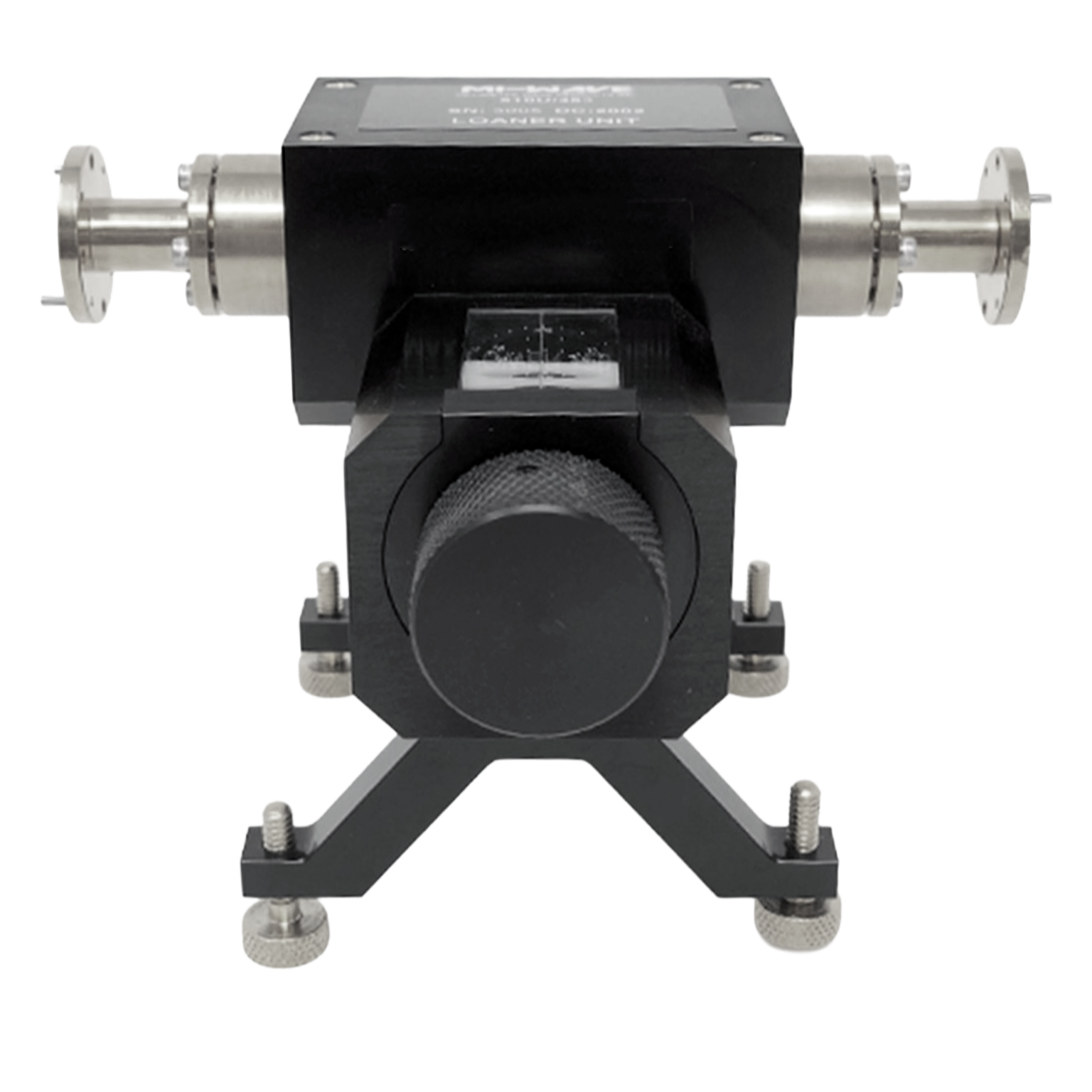
Mi-Wave’s 510 Series Direct-reading Precision Attenuators provide 0 to 60 dB of calibrated attenuation by rotation of a resistive vane mounted in a circular waveguide section. These units are often referred to as precision rotary vane attenuators.
Features
• Low VSWR
• Direct Reading
• Low Insertion Loss
• Anti-backlash Drive
• Negligible Phase Shift
• Precision Construction
• Frequency Independent
• Full Band Operation
• High Attenuation Accuracy
Applications
• Instrumentation
• Manual Test Setups
The standard models shown represent only part of Mi-Wave’s broader product capabilities. Custom configurations are available to support specific frequency bands, interfaces, and application requirements, enabling optimized solutions for specialized RF, microwave, and millimeter-wave systems.
*Actual product may be different from the image shown per customers specifcations
*All data presented is collected from a sample lot.
* Actual data may vary unit to unit, slightly.
*All testing was performed under +25 °C case temperature.
*Consult factory to confirm if material, plating, size, shape, orientation and any electrical parameter is critical for the application as website information is for reference only.
*Millimeter Wave Products, Inc. reserves the right to change the information presented on website without notice as we continue to enhance the performance and design of our products.
Features & Specifications
MI-Wave’s 510 Series Direct Reading Precision Attenuators are engineered to provide accurate, repeatable signal control across standard waveguide bands from X-Band to J-Band, covering frequency ranges from approximately 10.0 GHz to 220 GHz. Combining precision mechanical design with stable RF performance, these attenuators are well suited for laboratory measurements, calibration work, microwave system evaluation, and millimeter-wave testing.
Direct Reading Attenuation Control
A precision-calibrated mechanical dial allows attenuation levels to be set directly and read easily, helping streamline test setup and improve repeatability in measurement environments.
Frequency Coverage: X-Band to J-Band
Available across waveguide bands from X-Band through J-Band, the 510 Series supports a broad range of microwave and millimeter-wave applications, covering approximately 10.0 GHz to 220 GHz depending on waveguide size and model configuration.
Waveguide Sizes: WR-75 to WR-3
The 510 Series is available in waveguide configurations from WR-75 through WR-3, allowing integration into a wide range of standard rectangular waveguide systems used in RF, microwave, and mmWave environments.
Attenuation Range: Model Dependent
Multiple attenuation ranges are available to support signal level adjustment, system calibration, receiver testing, and general RF measurement applications.
High Accuracy and Repeatability
Designed for precision test applications, the 510 Series provides consistent attenuation settings across repeated adjustments, making it ideal for calibration benches and engineering labs.
Low VSWR
Good impedance matching helps minimize reflections and maintain measurement reliability across the operating band.
Low Insertion Loss
The design helps preserve signal integrity by minimizing unwanted loss beyond the selected attenuation value.
Precision Waveguide Interfaces
Manufactured with standard precision waveguide interfaces for dependable mechanical fit and electrical performance in microwave and millimeter-wave systems.
Stable Mechanical and Electrical Performance
Built for reliable operation over repeated use, these attenuators are designed to maintain dependable performance in controlled laboratory and test environments.
Smooth Mechanical Adjustment
The direct reading mechanism allows fine, controlled attenuation changes for accurate signal tuning without abrupt variation.
Rugged Laboratory-Grade Construction
The 510 Series is built for long-term use in demanding RF and microwave test setups where repeatable performance is essential.
Applications
MI-Wave’s 510 Series Direct Reading Precision Attenuators are used across microwave and millimeter-wave systems where accurate, repeatable signal control is required from 10 GHz to 220 GHz.
RF & Microwave Test Systems
Used in laboratory environments to precisely control signal levels during testing of amplifiers, mixers, receivers, and complete RF chains operating across X, Ku, Ka, and higher frequency bands.
Calibration & Metrology Laboratories
Ideal for calibration setups requiring repeatable attenuation settings without external measurement verification, supporting accurate instrument calibration and traceable measurement standards.
Millimeter Wave Testing (mmWave)
Supports high-frequency testing in waveguide systems from WR-75 to WR-3, making it suitable for mmWave development, component characterization, and advanced research applications.
Receiver Sensitivity & Dynamic Range Testing
Allows engineers to reduce signal levels in a controlled and repeatable manner to evaluate receiver performance, noise floor, and minimum detectable signal.
Signal Conditioning in Waveguide Systems
Used between components such as amplifiers, detectors, and converters to maintain proper signal levels and prevent overload or distortion in microwave and mmWave systems.
Engineering Development & Prototyping
Provides flexible, hands-on attenuation control for rapid system tuning and troubleshooting during RF design and development.
Aerospace & Defense RF Systems
Applicable in radar, electronic warfare, and communication systems where stable, repeatable attenuation across wide frequency ranges is critical.
Frequently Asked Questions (FAQ)
What is a direct reading precision attenuator?
A direct reading precision attenuator is a waveguide or coaxial device that allows users to set attenuation levels using a calibrated dial, providing accurate and repeatable signal reduction without requiring external measurement tools.
What frequency range does the 510 Series cover?
The 510 Series operates across X-Band to J-Band, covering approximately 10 GHz to 220 GHz, depending on the waveguide size and configuration.
What waveguide sizes are available?
These attenuators are available in standard waveguide sizes from WR-75 through WR-3, supporting both microwave and millimeter-wave systems.
Why use a direct reading attenuator instead of an electronic attenuator?
Direct reading attenuators offer simplicity, reliability, and immediate accuracy, making them ideal for calibration labs and manual test setups where repeatability and stability are more important than remote control.
Are these attenuators suitable for calibration applications?
Yes, they are specifically designed for calibration and metrology environments where precise, repeatable attenuation settings are required.
Do these attenuators require external calibration equipment?
No, the direct reading dial provides a calibrated attenuation value, reducing the need for external verification during setup.
Can the 510 Series be used in millimeter-wave systems?
Yes, with waveguide options extending to WR-3, the 510 Series supports millimeter-wave applications up to approximately 220 GHz.
RF Attenuator Calculators
These RF attenuator calculators are designed to support microwave and millimeter-wave engineers working with direct reading precision attenuators, waveguide attenuators, and laboratory RF test setups. Use these tools to quickly convert attenuation values, estimate power levels, evaluate cascaded loss, and analyze impedance match performance for systems spanning X-Band through J-Band.
dB to Power Ratio
Convert attenuation or gain in decibels to a linear power ratio.
Power Ratio to dB
Convert a linear power ratio into decibels.
dBm to Watts
Convert RF power in dBm to watts for test and system-level calculations.
Watts to dBm
Convert watts to dBm for RF signal level analysis.
Cascaded Attenuation Calculator
Add multiple attenuator values together to determine total path attenuation.
VSWR to Return Loss
Estimate return loss from a known VSWR value.
Glossary of Direct Reading Precision Attenuator Terms
Attenuator Fundamentals
Direct Reading Attenuator
A precision attenuator that allows attenuation levels to be set and read directly using a calibrated mechanical dial.
Waveguide Attenuator
An attenuator designed for use in rectangular waveguide systems to reduce RF signal power at microwave and millimeter-wave frequencies.
Manual Attenuator
An attenuator adjusted by hand rather than by electronic or automated control.
Precision Attenuator
An attenuator built for highly accurate, repeatable signal reduction in test, calibration, and measurement environments.
Electrical Performance
Attenuation (dB)
The reduction of signal power expressed in decibels.
Insertion Loss
The signal loss introduced when a component is inserted into an RF transmission path.
VSWR (Voltage Standing Wave Ratio)
A measure of how well the attenuator is impedance matched to the system.
Return Loss
The amount of reflected signal caused by impedance mismatch.
Repeatability
The ability of the attenuator to provide the same attenuation setting consistently over repeated use.
Power Handling
The maximum RF power the attenuator can safely handle without damage or degraded performance.
RF and Frequency
Radio Frequency (RF)
Electromagnetic signals used for communication, sensing, testing, and measurement.
Waveguide Terms
Waveguide
A hollow metallic structure used to guide RF energy, especially at microwave and millimeter-wave frequencies.
Rectangular Waveguide
The most common waveguide format used for microwave and mmWave systems, defined by standard WR sizes.
Waveguide Size
The physical dimensions of a waveguide, which determine its usable frequency range.
Waveguide Bandwidth
The range of frequencies over which a waveguide can efficiently transmit RF energy.
Measurement and Calibration
Calibration
The process of verifying measurement accuracy using known standards and reference components.
Metrology
The science of measurement, especially important in precision RF and microwave testing.
Signal Level Control
The adjustment of RF power to achieve the desired level in a system or test setup.
Dynamic Range
The span between the smallest and largest signal levels a system can measure or process accurately.
Receiver Sensitivity Testing
A test used to determine the lowest signal level a receiver can reliably detect.
System and Applications
Test & Measurement Systems
Equipment and setups used to evaluate the performance of RF and microwave components.
Calibration Laboratories
Specialized environments where instruments and RF components are verified for accuracy and repeatability.
Signal Conditioning
The process of adjusting or controlling a signal to meet the requirements of a system or test setup.
Microwave Systems
RF systems operating in the microwave frequency range for communications, radar, and testing.
Millimeter-Wave Systems
High-frequency systems operating above 30 GHz, often used in advanced radar, communications, and research.
RF System Integration
The process of combining RF components into a complete working system.
Engineering Concepts
Impedance Matching
The practice of matching component impedances to minimize reflections and maximize power transfer.
Signal Integrity
The preservation of signal quality without excessive loss, distortion, or reflection.
Reflection Coefficient
A value that indicates how much of a signal is reflected due to impedance mismatch.
Stable Performance
Consistent electrical and mechanical behavior over time and repeated operation.
Mechanical Adjustment
Manual control of attenuation through a dial or other physical adjustment mechanism.
Note: Our website contains just a few types of Attenuators we build. Consult with us for your specific needs.
| Model | Band Type | Minimum Frequency (GHz) | Maximum Frequency (GHz) | Insertion Loss (dB) typical | Attenuation Range (dB) | Power Handling (CW) | RF Ports | Accuracy (dB) | LINK |
|---|---|---|---|---|---|---|---|---|---|
| 510X/39 | X-Band | 8.2 | 12.4 | 0.5 | 0-50 | 0.3 | WR-90 Waveguide, UG-39/U Flange | 0.1 | |
| 510(75)/UBR120 | WR-75 | 10 | 15 | 0.5 | 0-50 | 0.3 | WR-75Waveguide, UG-UBR120 Flange | 0.1 | |
| 510Ku/419 | Ku-Band | 12.4 | 18 | 0.5 | 0-60 | 0.3 | WR-62 Waveguide, UG-419 Flange | 0.1 | |
| 510K/595 | K-Band | 18 | 26.5 | 0.5 | 0-60 | 0.3 | WR-42 Waveguide, UG-595/U Flange | 0.1 | |
| 510(34)/1530 | WR-34 | 22 | 33 | 0.5 | 0-60 | 0.2 | WR-34 Waveguide, UG-595 Flange | 0.1 | |
| 510A/599 | Ka-Band | 26.5 | 40 | 0.6 | 0-60 | 10 | WR-28 Waveguide, UG-599/U Flange | 0.1 | |
| 510B/383 | Q-Band | 33 | 50 | 0.7 | 0-60 | 7 | WR-22 Waveguide, UG-383/U Flange | 0.1 | |
| 510U/383 | U-Band | 40 | 60 | 0.7 | 0-60 | 5 | WR-19 Waveguide, UG-383/U-M Flange | 0.1 | |
| 510V/385 | V-Band | 50 | 75 | 1.2 | 0-60 | 5 | WR-15 Waveguide, UG-385/U Flange | 0.1 | |
| 510E/387 | E-Band | 60 | 90 | 1.8 | 0-60 | 2 | WR-12 Waveguide, UG-387/U-M Flange | 0.1 | |
| 510W/387 | W-Band | 75 | 110 | 3.3 | 0-60 | 2 | WR-10 Waveguide, UG-387/U-M Flange | 0.1 | |
| 510F/387 | F-Band | 90 | 140 | 3.4 | 0-50 | 0.1 | WR-8 Waveguide, UG-387/U-M Flange | 0.1 | |
| 510D/387 | D-Band | 110 | 170 | 3.5 | 0-50 | 0.1 | WR-6 Waveguide, UG-387/U-M Flange | 0.1 | |
| 510G/387 | G-Band | 140 | 220 | 3.8 | 0-40 | 0.1 | WR-5 Waveguide, UG-387/U-M Flange | 0.1 | |
| 510H/387 | H-Band | 170 | 260 | 6 | 0-40 | 0.1 | WR-4 Waveguide, UG-387/U-M Flange | 0.1 | |
| 510J/387 | J-Band | 220 | 325 | 7 | 0-40 | 0.05 | WR-03 Waveguide, UG-387/U-M Flange | 0.1 |