
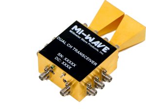
How to Select the Right Microwave Frequency Converter
Every microwave link, radar, and test setup eventually has to move a signal from one frequency to another. A modem works at an intermediate frequency, the antenna works at the carrier, and the converter between them decides how much of the signal’s quality survives the trip.
Picking one on band alone is where trouble starts. Reference stability, IF interface, channel count, and packaging all shape how a converter behaves once it is in the system, and each is easier to settle before ordering than after integration.
What a Microwave Frequency Converter Does
A microwave frequency converter translates a signal from one frequency band to another by mixing it with a local oscillator. An upconverter shifts a lower intermediate frequency (IF) up to the RF band for transmission, a downconverter does the reverse for reception, and a transceiver combines both directions in a single unit.
Mi-Wave’s converter range covers synthesized upconverters and downconverters, up-downconverter transceivers, block upconverters, multi-channel units, and custom RF frequency converters, so the first decision is which of those structures matches your signal path.
Start With Your RF Band and Conversion Direction
Converters are built for a defined RF range. Mi-Wave’s catalog starts around 2 GHz and reaches 110 GHz, with units for Ku, Ka, Q, U, E, and W bands and a 50-110 GHz broadband downconverter for wideband work. Confirm the exact RF range your system occupies, and note that a band name alone can be ambiguous because different sources draw the edges differently. Work from frequencies in GHz, not band letters.
Then decide on direction. A transmit-only chain needs an upconverter, a receive-only chain needs a downconverter, and a terminal that does both can save space and interconnects with an up-downconverter transceiver.
Define Your IF and Reference Requirements
The IF side of the converter has to match the equipment it connects to. Common IF choices include 70 MHz, 140 MHz, and L-band, which spans 950 to 2150 MHz, and the converter’s input and output must line up with your modem or digitizer, not just the antenna side.
Reference input matters just as much. A synthesized converter derives its local oscillator from a reference, commonly 10 MHz, so the stability and phase noise of that reference carry through to the converted signal. If your system already distributes a house reference, confirm the converter can lock to it.
Choose Between Synthesized and Block Converters
A synthesized converter uses a frequency synthesizer for its local oscillator, which gives flexibility in choosing the conversion frequency and works well when the frequency plan needs to be set precisely. A block converter shifts an entire span of spectrum in a single step, which suits satellite and point-to-point systems that move many carriers together. Decide which approach fits your frequency plan before comparing individual models.
Decide on Channel Count and Packaging
Converters are available in one-, two-, three-, and four-channel configurations, and the right count depends on how many signal paths you are building. Multi-channel units keep paths in one housing, which helps with channel-to-channel consistency and rack space. Packaging also varies, including rack-mounted environmental units, and some downconverters are offered with an integrated omnidirectional antenna for 14-16 GHz and 27-29 GHz applications.
If your requirement doesn’t match a standard unit, custom frequency converters can be built to a specific band, IF, and interface.
Check the Performance Numbers
A few figures determine how much a converter changes the signal passing through it:
- Conversion Gain: how much the signal is amplified or attenuated in translation. It sets the level relationship between your IF source and the RF stage.
- Noise Figure: how much noise the converter adds, which matters most in downconverters at the front of a receive chain.
- Output Power and Linearity: how much signal an upconverter can deliver before it distorts, which sets the headroom for the following amplifier.
- Phase Noise and Spurious Output: how clean the converted signal stays, which affects modulation quality and adjacent-channel interference.
Request these figures for the specific model and band you are considering instead of inferring them from a catalog listing.
Confirm the Waveguide or Connector Interface
Millimeter-wave converters commonly present their RF port as a waveguide flange or a precision connector, and the interface must match the rest of your RF path. Part numbers carry codes for flange types such as UG-383, UG-387, and UG-599, and some units use 1.85 mm connectors. Standard waveguide sizes in this range include WR-28, WR-22, WR-15, and WR-10. Every adapter added between the converter and the antenna or test port is another source of loss and mismatch.
Match the Converter to the Application
Satellite communication terminals and gateways use converters to move signals between IF and the uplink and downlink bands. Point-to-point microwave and mmWave backhaul links rely on them in the radio’s RF section. Radar systems use them in surveillance, weather, and pulse-Doppler designs, while telemetry systems use them across aerospace, defense, and UAV links. In the lab, 5G FR2 and mmWave test setups use converters to extend instruments to higher bands, and radio astronomy and other research systems use them to bring weak signals down to a workable IF.
Common Selection Mistakes to Avoid
- Choosing by band letter: instead of confirming the actual start and stop frequencies the system needs.
- Overlooking the IF interface: and discovering the converter’s IF doesn’t match the modem or digitizer.
- Ignoring reference quality: when phase noise requirements are tight.
- Buying the wrong direction: or channel count and then adding a second unit to make up the difference.
- Stacking adapters: between the converter and the rest of the RF path, adding loss that was never in the link budget.
Where This Kind of Component Comes From
Frequency converters at millimeter-wave bands are built by a limited number of specialized manufacturers, since they combine mixers, synthesizers, filtering, and precision RF packaging in one unit. Mi-Wave is one of them, producing converters alongside a wider catalog of waveguide and millimeter-wave components for satellite, radar, backhaul, and test systems.
Conclusion
Choosing a microwave frequency converter isn’t about finding the widest band on a list. It is about matching the RF range, the direction of conversion, the IF and reference interfaces, and the channel count to the system you are actually building. Settle those fundamentals, confirm the performance figures for your exact model, and the converter does its job without becoming the weak link.
If you are specifying a converter for a SatCom terminal, backhaul radio, or test setup and want to work through frequency plan and interface details before choosing a model, Contact Us and our engineering team can help match a configuration to your system.