
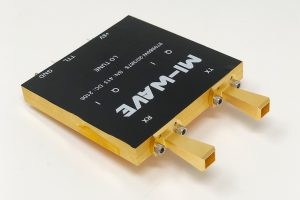
How to Choose an RF Up Down Converter
A frequency converter can pass every bench test in isolation and still wreck a system’s error vector magnitude the moment it’s installed, because the number that actually matters – local oscillator phase noise – rarely shows up as a headline spec until the modulation scheme gets demanding enough to expose it.
That converter sits at the boundary between the frequency your antenna or amplifier operates at and the frequency your baseband or IF electronics can actually process. Downconverters translate a high-frequency RF signal down to a workable IF; upconverters do the reverse on transmit. Specifying one on frequency range alone, without weighing phase noise, stability, and tuning resolution, is how a system ends up with a perfectly capable RF front end that still can’t hit its bit-error-rate target.
What an RF Up Down Converter Actually Does
An rf up down converter performs frequency translation: a downconverter shifts a high-frequency RF signal to a lower Intermediate Frequency using a stable Local Oscillator, making the signal easier to filter, digitize, and process; an upconverter reverses the process on transmit, moving an IF signal up to RF for radiation. Pair an upconverter with a power amplifier and you get a Block Upconverter, or BUC; pair a downconverter with a low noise amplifier and you get a Low Noise Block Downconverter, or LNB – the same core translation function built into two of the most common building blocks in satellite and microwave systems.
Because the LO is what actually performs the translation, its quality, not the mixer or the filtering around it, is usually what determines whether the converted signal is still usable on the other side.
Start With Both Frequency Bands, Not Just One
A converter is specified by two frequencies, not one: the RF band and the IF it translates to or from. Mi-Wave’s frequency converter line covers X-band (8-12 GHz), Ku-band (12-18 GHz), Ka-band (26-40 GHz), Q-band (33-50 GHz), V-band (40-75 GHz), and W-band (75-110 GHz) and beyond, with models built around specific band pairs – a 980-2/18/10/smaF, for example, upconverts across 2-18 GHz with a synthesized block architecture. Confirm both ends of the translation, and whether you need an upconverter, a downconverter, or a combined up/down unit, before narrowing down a model.
Check Local Oscillator Phase Noise and Frequency Stability First
Phase noise on the LO carries straight through to the converted signal, and it’s what determines whether a high-order modulation scheme stays inside its error budget. This matters most on narrowband carriers and dense constellations, where excess phase noise shows up directly as degraded EVM and bit-error-rate rather than as an obvious failure. Frequency stability matters just as much for systems running over long periods or across changing temperatures – satellite ground equipment and precision measurement systems in particular depend on stability holding up over time, not just at the moment the unit ships.
Confirm Tuning Resolution, Gain Control, and Channel Count
Beyond frequency and phase noise, the practical fit comes down to a few configuration options that vary unit to unit:
- Tuning Resolution: fine frequency steps let you place channels precisely within a crowded spectrum, which matters more in lab and multi-channel environments than in a fixed single-channel link.
- Gain Control: integrated digital attenuation or AGC keeps output level stable across varying input power, which simplifies calibration and protects downstream stages from compression.
- Channel Count: converters are commonly available in 1, 2, 3, or 4-channel configurations, and matching that to your system reduces rack footprint instead of running separate single-channel units side by side.
Watch Image Rejection and LO Leakage
A converter with weak image rejection lets an unwanted mixing product through alongside the signal you actually want, degrading the clean spectrum you’re trying to produce or receive. Poor LO-to-RF or LO-to-IF isolation causes LO leakage, which shows up as spurious emissions and can interfere with adjacent channels or fail spectral compliance requirements outright. Both numbers matter more as channel spacing gets tighter, so weigh them more heavily in dense multi-channel or regulated spectrum environments.
Match the Converter to the Application
Satellite communication systems depend on converters built into BUCs and LNBs for uplink and downlink translation, where phase noise and stability directly set link margin. Radar and telemetry systems use converters to bring return signals down to a processable IF while preserving weak-signal integrity. 5G and microwave backhaul links rely on stable frequency translation to keep high-order modulation schemes within spec over a live link. Test and measurement environments use converters to translate signals into instrument-compatible ranges without adding their own distortion to the measurement.
Common Selection Mistakes to Avoid
- Specifying the RF band only, without confirming the IF and the exact translation the system actually needs.
- Treating phase noise as a secondary spec, then troubleshooting EVM or bit-error-rate problems that trace straight back to the LO.
- Relying on an internal reference for a multi-unit system that actually needs an external reference for synchronization across converters.
- Underspecifying channel count or gain control up front, then bolting on separate units or manual attenuators later.
Where This Kind of Component Comes From
RF frequency converters are built by a relatively small number of specialized manufacturers, since low phase noise and high image rejection at microwave and millimeter-wave frequencies require dedicated LO and mixer design rather than off-the-shelf modules. Mi-Wave is one of the manufacturers producing this class of hardware, alongside a broader catalog of waveguide and millimeter-wave components for satellite, radar, and defense-oriented systems.
Conclusion
Choosing an RF up down converter isn’t about matching a single frequency range off a datasheet. It’s about confirming both the RF and IF bands, prioritizing LO phase noise and stability for your modulation scheme, and sizing tuning resolution, gain control, and channel count to how the system will actually run. Get those fundamentals right, and the converter stops being a hidden source of EVM and bit-error-rate problems and becomes a transparent link between your RF front end and your baseband electronics.
If you’re specifying a converter for a demanding phase noise or multi-channel requirement and want to work through the numbers before committing to a part, Contact Us and our engineering team can help match a configuration to your system.
