
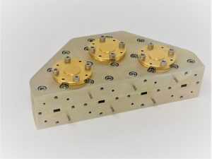
How to Specify a Waveguide Power Combiner
In a multi-amplifier RF chain, the failure that’s hardest to diagnose isn’t a bad amplifier – it’s a combiner quietly throwing away power because the signals feeding it were never balanced the way the datasheet assumed. Two solid-state amplifiers can each check out perfectly on the bench and still lose real output power the moment they’re combined, and the component responsible is almost never the first thing inspected.
That component is the power combiner – the same waveguide hardware sold as a power divider, just run in the opposite direction. Splitting a signal evenly and combining two signals into one both depend on the same amplitude balance, phase balance, and port isolation, so a part chosen only for its frequency range and way-count can still underperform once amplifiers, not a single clean source, are on the input side.
What a Waveguide Power Combiner Actually Does
A waveguide power combiner is a reciprocal three-or-more-port waveguide device: send equal signals into what are normally the output ports of a divider, and they add together at the input port, ideally with no loss beyond the waveguide’s own insertion loss. Mi-Wave’s E/H Hybrid and Magic Tees, for example, use three mutually perpendicular flanged waveguide sections – two positioned symmetrically on the broad and narrow walls of the main tee – to provide both E-plane and H-plane connections in a single unit, giving in-phase splitting or combining depending on which ports carry the signal.
Because the device is fully passive and reciprocal, everything that determines how cleanly it splits a signal also determines how cleanly it combines one. That’s worth remembering when a datasheet only shows divider performance – a combiner application inherits the exact same amplitude balance, phase balance, and isolation requirements.
Start With Your Frequency Band and Waveguide Size
Waveguide power combiners are built to a specific band and waveguide size, not a broad catalog spec. Standard coverage runs from roughly 8.0 GHz up to 140.0 GHz across the usual waveguide bands, with dedicated configurations available for common 5G ranges such as 24.25-29.5 GHz, 37.0-43.5 GHz, and 45.5-52.6 GHz through 95-110 GHz. Confirm the exact band your amplifier chain or antenna array operates in and match it to the standard waveguide size before comparing way-counts or part numbers – a combiner rated for an adjacent band won’t hold its balance or isolation numbers outside its designed range.
Choose the Right Way-Count for Your Combining Stage
Combiners are built in fixed way-counts – 2-way, 4-way, and 8-way are standard – and the right one depends on how many sources you’re actually combining, not how much total power you eventually need. A 2-way magic or hybrid tee is the basic building block; larger combining networks are typically built by cascading 2-way stages, which is why 4-way and 8-way units exist as purpose-built assemblies rather than ad hoc combinations of smaller parts. Match the way-count to your amplifier module count first, then check that the resulting combined output and any spare ports are handled the way your system needs.
Check Amplitude Balance, Phase Balance, and Isolation
A few numbers determine how much of your combined power actually shows up at the output instead of being wasted:
- Amplitude Balance: how closely the power level matches across the ports being combined. A mismatch here means the combiner treats the excess as reflected energy rather than useful output.
- Phase Balance: how closely the signals align in phase before combining. Even well-matched amplitude sources lose power to destructive interference if their phase drifts apart.
- Isolation: how well the ports are isolated from each other. In a combining application, isolation is what keeps power from one amplifier leaking back into another instead of adding constructively at the output.
Confirm Waveguide Interface and Flange Compatibility
Like any waveguide component, a power combiner ships with a fixed flange type and port orientation, and matching that to your existing waveguide run matters as much as matching the frequency band. A mismatched flange means an adapter, and every adapter ahead of a combining stage adds another point of insertion loss and VSWR degradation before the signal ever reaches the combiner. Confirm flange type and port spacing against your amplifier module layout before ordering, particularly when the combining stage sits inside a densely packed transmit assembly.
Match the Combiner to the Application
Solid-state power amplifier arrays use combiners to add the output of multiple amplifier modules into a single high-power transmit path, so amplitude and phase balance across every module matter most. Beam-forming and phased-array front ends use the same hardware in reverse, splitting a signal across many elements while preserving phase relationships. 5G millimeter-wave systems rely on compact combiner networks to aggregate multiple power amplifier chains within a tightly packed radio unit. Test and measurement setups use combiners to merge signal sources for two-tone or multi-tone testing, where isolation between sources is what keeps the test signal clean.
Common Selection Mistakes to Avoid
- Assuming a combiner will compensate for amplitude or phase mismatch between amplifier modules, rather than fixing the imbalance ahead of the combining stage.
- Choosing a way-count that doesn’t match the actual number of sources being combined, then padding or terminating unused ports as an afterthought.
- Ignoring the isolated port’s power handling when combining unequal sources – the difference in power has to be dissipated somewhere, and that port needs to handle it.
- Overlooking flange and adapter losses stacked ahead of the combiner, then troubleshooting a power budget that was never wrong at the combiner itself.
Where This Kind of Component Comes From
Waveguide power dividers and combiners are built by a relatively small number of specialized manufacturers, since achieving tight amplitude and phase balance across a broad band requires precision waveguide machining and careful electrical design. Mi-Wave is one of the manufacturers producing this class of hardware, alongside a broader catalog of waveguide and millimeter-wave components for radar, satellite, and 5G systems.
Conclusion
Choosing a waveguide power combiner isn’t about picking the highest way-count available. It’s about matching the frequency band and waveguide size, sizing the way-count to your actual number of sources, and confirming that amplitude balance, phase balance, and isolation hold up across the full operating band. Get those fundamentals right, along with a flange that drops straight into your existing waveguide run, and the combiner adds power cleanly instead of quietly losing it.
If you’re specifying a combiner for a multi-amplifier transmit chain or a phased-array front end and want to work through the balance and isolation numbers before committing to a part, Contact Us and our engineering team can help match a configuration to your system.
