
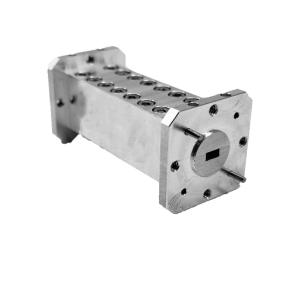
Every RF or microwave system deals with unwanted energy somewhere in the signal path: harmonics from an amplifier, image frequencies from a mixer, spurious content from a frequency multiplier, or simply out-of-band noise picked up along the way. Left unmanaged, that energy competes with the signal you actually want.
A frequency-selective passive component solves this by passing a defined range of frequencies while rejecting everything outside it. These parts show up in satellite communications, radar, electronic warfare, and RF test systems wherever spectral cleanliness matters.
This guide covers how the component works, the parameters that actually describe its performance, how to choose one for a given application, and where it typically sits in a larger signal chain.
What Is a Waveguide Bandpass Filter and How Does It Work
A waveguide bandpass filter passes a specific frequency range, the passband, while attenuating frequencies above and below it. Internally, it behaves like a highpass and lowpass filter combined: energy below the lower cutoff and above the upper cutoff is reflected or attenuated, while energy inside the band passes through with minimal loss. In a waveguide implementation, this filtering behavior comes from precisely machined resonant cavities or iris structures inside the waveguide section rather than from lumped inductors and capacitors, which makes it possible to hold tight tolerances at frequencies where lumped components become impractical.
Passband, Rejection, and the Trade-off Between Them
Every filter design balances passband performance against rejection performance. A waveguide bandpass filter with very high out-of-band rejection typically costs some insertion loss inside the passband, and a design optimized for the lowest possible insertion loss usually gives up some rejection steepness. Mi-Wave’s 460 Series spans roughly 8 GHz to 140 GHz with configurable bandwidths from about 1 percent to 10 percent of center frequency, which is enough range to cover most narrowband and moderately wideband requirements.
Key Parameters That Define Filter Performance
- Center frequency and passband — the frequency range the filter is designed to pass with minimal attenuation.
- Bandwidth (absolute and fractional) — how wide the passband is, usually expressed as a percentage of center frequency.
- Insertion loss — signal loss inside the passband; lower is better for preserving system sensitivity or output power.
- Out-of-band rejection — how strongly the filter attenuates frequencies outside the passband, usually specified in dB at defined offset frequencies.
- Return loss / VSWR — how well the filter is impedance-matched at both the passband edges and center frequency.
- Waveguide size and interface — determines the physical flange and mounting compatibility with the rest of the system.
How to Choose the Right Waveguide Bandpass Filter
1. Define the Passband You Actually Need
Start with the exact center frequency and bandwidth required, not just the general waveguide band. A narrower passband gives better rejection close to the passband edges but adds insertion loss and manufacturing complexity.
2. Set Rejection Requirements Based on the Interferer
Identify what you’re trying to reject — a harmonic, an image frequency, an adjacent channel — and how far in frequency it sits from the passband. Interferers close to the passband edge require steeper filter designs than ones far removed.
3. Balance Insertion Loss Against Rejection
In receive chains, insertion loss ahead of a low noise amplifier degrades system noise figure directly, so tighter rejection specs need to be weighed against their cost in loss. In transmit chains feeding a power amplifier, insertion loss translates directly into wasted output power.
4. Confirm Waveguide Size and Mechanical Fit
Match the waveguide size and flange type to the rest of the system, and confirm the filter’s temperature and environmental ratings if it will operate outside a controlled lab environment.
Where Bandpass Filters Fit in a Signal Chain
A bandpass filter rarely works alone. It’s commonly placed ahead of a low noise amplifier to strip out-of-band interference before it reaches sensitive receive electronics, after a frequency multiplier or mixer to remove unwanted harmonics and spurious products, or alongside a waveguide circulator in duplexer configurations that separate transmit and receive paths sharing a single antenna.
Common Applications
- Satellite communications, isolating uplink and downlink bands and suppressing out-of-band interference.
- Radar systems, improving target detection and reducing clutter by protecting the receiver front end.
- Electronic warfare and SIGINT, where high selectivity and strong out-of-band rejection are essential.
- Frequency conversion chains, removing unwanted mixer products after upconversion or downconversion.
- RF test and measurement, ensuring accurate, repeatable results at microwave and millimeter-wave frequencies.
Mi-Wave’s 460 Series filters are frequently specified alongside circulator and isolator components in these systems, since all three are passive parts doing complementary jobs: routing, protecting, and cleaning up the signal path.
Final Thoughts
A waveguide bandpass filter is a simple concept: pass one range of frequencies, reject the rest. But getting the passband, rejection, and insertion loss trade-offs right requires knowing exactly what the filter needs to reject and where it sits in the chain. Mi-Wave’s 460 Series covers 8 GHz to 140 GHz in both standard and custom configurations, and the engineering team can help match a filter’s passband and rejection profile to a specific interferer or system requirement.
