
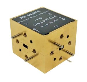
What Is a Waveguide Circulator? How It Works?
In any RF or microwave signal chain, controlling which direction energy flows matters just as much as generating or receiving it. A radar transmitter and its sensitive receiver often share the same antenna. A satellite ground terminal may route uplink and downlink signals through the same waveguide run. Without something to manage that shared path, reflected power and cross-talk between components can degrade performance or damage sensitive electronics.
This is where a passive, three-port ferrite device earns its place in the signal chain. It routes microwave energy from one port to the next in a single, predictable direction, letting engineers separate transmit and receive paths, protect sources from reflected power, and combine signals without adding active circuitry. These devices show up constantly in radar, satellite communications, electronic warfare, and RF test setups.
This guide covers what the device is, how it works internally, the specifications that actually matter when selecting one, where it’s typically used, and how it differs from a closely related component: the isolator. The goal is to keep this practical rather than purely theoretical, since most sourcing mistakes come from skipping this groundwork rather than from a lack of theory.
What Is a Waveguide Circulator and How Does It Work
A waveguide circulator is a passive, non-reciprocal microwave component with three (occasionally four) ports arranged around a central ferrite junction. Signal energy entering any port exits almost entirely from the next port in a fixed rotational direction -typically clockwise -while the port behind it sees very little of that same signal. Because the behavior depends on direction rather than any switching element, there’s nothing to control, bias, or fail the way a diode switch might.
The Role of Ferrite and Magnetic Bias
The non-reciprocal behavior comes from a magnetized ferrite element sitting inside the waveguide junction. A permanent magnet biases the ferrite, and that magnetic field interacts with the microwave signal’s polarization as it passes through. The interaction rotates the signal’s field pattern by a controlled amount, aligning it with the geometry of the next port so it exits there with minimal loss, while suppressing transmission back toward the port it came from. No external power supply or control voltage is needed -the magnet does the work continuously.
Y-Junction vs. Multi-Junction Designs
Most waveguide circulators fall into one of two mechanical families. A Y-junction circulator uses a single ferrite junction shaped like the letter Y, with three ports meeting at 120-degree angles -the simplest and most common configuration. A multi-junction circulator cascades two or three of these junctions inside one housing, which typically extends usable bandwidth and pushes isolation higher than a single junction can reach, at the cost of a slightly larger footprint and marginally higher insertion loss. Mi-Wave’s own lineup reflects this split: the 179 Series is a Y-junction waveguide circulator covering 18 GHz to 110 GHz, while the 180 Series handles multi-junction configurations built for applications that need extra isolation margin.
Key Specifications That Actually Matter
When comparing options, the datasheet numbers that affect real-world performance are:
- Frequency range and waveguide size -determines which standard waveguide band (K, Ka/A, Ku, U, V, E, W, etc.) and flange type you need; get this wrong and nothing else on the list matters.
- Isolation (dB) -how well the device blocks signal from flowing backward into the port behind the active path; typical units land between 15 and 20+ dB minimum.
- Insertion loss (dB) -the loss the wanted signal takes passing through in the forward direction; well-built units run under 1 dB across most bands.
- VSWR -reflects how well each port is impedance-matched; a mismatched unit reflects energy right back where you didn’t want it.
- Power handling -average and peak power ratings, which matter far more in transmit chains than in low-level test or receive paths.
- Bandwidth -the frequency span across which the specs above hold; broader bandwidth generally trades off against isolation and insertion loss.
How to Choose the Right Waveguide Circulator for Your System
Picking the right unit is less about finding the “best” component and more about matching specs to the job at hand.
1. Start With Your Operating Band
Identify the exact frequency range and corresponding waveguide size (WR-42, WR-28, WR-22, WR-15, WR-12, WR-10, and so on) your system uses. These components are band-specific by design, so this narrows the field immediately.
2. Set Isolation and Insertion Loss Targets Based on the Application
A test bench protecting a signal generator from load mismatches can tolerate more insertion loss than a transmit chain feeding a high-power amplifier, where every tenth of a dB matters. Radar and EW systems typically push for higher isolation to keep leakage out of sensitive receive paths.
3. Confirm Power Handling and Environmental Ratings
Match average and peak power ratings to your actual signal levels, not just nominal output -reflected power during a mismatch can spike well above steady-state levels. Also check the operating temperature range if the unit will sit in an outdoor enclosure or an airborne platform.
4. Decide Whether You Need a Circulator or an Isolator
If the goal is only to protect a source from reflected energy -rather than route signals between multiple paths -a two-port waveguide isolator may be the simpler, more cost-effective choice.
Common Applications
These components show up wherever RF energy needs to move in one direction without active switching:
- Radar systems, where a single antenna transmits and receives, and the device keeps the outgoing pulse from swamping the receiver.
- Satellite communication ground terminals, separating uplink and downlink paths that share common waveguide runs.
- Electronic warfare and test equipment, protecting signal sources and amplifiers from reflected power during impedance mismatches.
- Radar target simulators and calibration setups, where predictable, low-loss signal routing is critical to accurate measurements.
Mi-Wave’s 179 and 180 Series circulators are built for exactly this kind of duty -machined and tested to hold their specifications across the full rated band rather than just at center frequency.
Circulator vs. Isolator: What’s the Difference
The two components share the same ferrite-and-magnet operating principle, which is why they’re often confused. A circulator has three ports and actively routes signal from each port to the next. A waveguide isolator is effectively a circulator with its third port permanently terminated in a matched load -energy still enters one port and exits the next, but anything reflected back gets absorbed instead of routed anywhere useful. That makes an isolator a simpler, cheaper way to solve a narrower problem: protecting a single source or amplifier from its own reflections, without needing to route signal anywhere else. When a design calls for multi-path routing, like sharing one antenna between a transmitter and receiver, a circulator is the right tool. When the only goal is shielding one component from reflected energy, an isolator usually does the job at lower cost.
Installation and Mechanical Interfacing
Getting the specifications right only pays off if the physical installation matches. These parts mount using standard waveguide flanges (UG-595, UG-599, UG-383, UG-385, UG-387, depending on band), and the flatness of the mating surface directly affects insertion loss and VSWR at the joint -any gap or misalignment introduces a discontinuity the signal has to cross. Orientation matters too: because the device is non-reciprocal, ports aren’t interchangeable, and installing it backward routes signal the wrong way rather than simply reducing performance. Most datasheets mark port 1, 2, and 3 clearly on the housing for this reason.
Final Thoughts
A waveguide circulator looks like a simple passive block, but it does real work protecting sensitive components and keeping signal paths clean in systems where a single reflection can cause measurable problems. Getting the frequency band, isolation, insertion loss, and power handling right up front avoids a costly re-spec later in a program. Mi-Wave’s engineering team works through these selection questions with customers regularly and can help match a stock 179 Series part, or a custom configuration, to a specific application.
