
Products> Antennas >Dual Polarized Antennas > Dual-Polarized Scalar Feed Horns
Product Description
RF Orthomode Transducers
Watch our informational video to learn more about this product family, including its key features, operating principles, and common applications.
The standard models shown represent only part of Mi-Wave’s broader product capabilities. Custom configurations are available to support specific frequency bands, interfaces, and application requirements, enabling optimized solutions for specialized RF, microwave, and millimeter-wave systems.
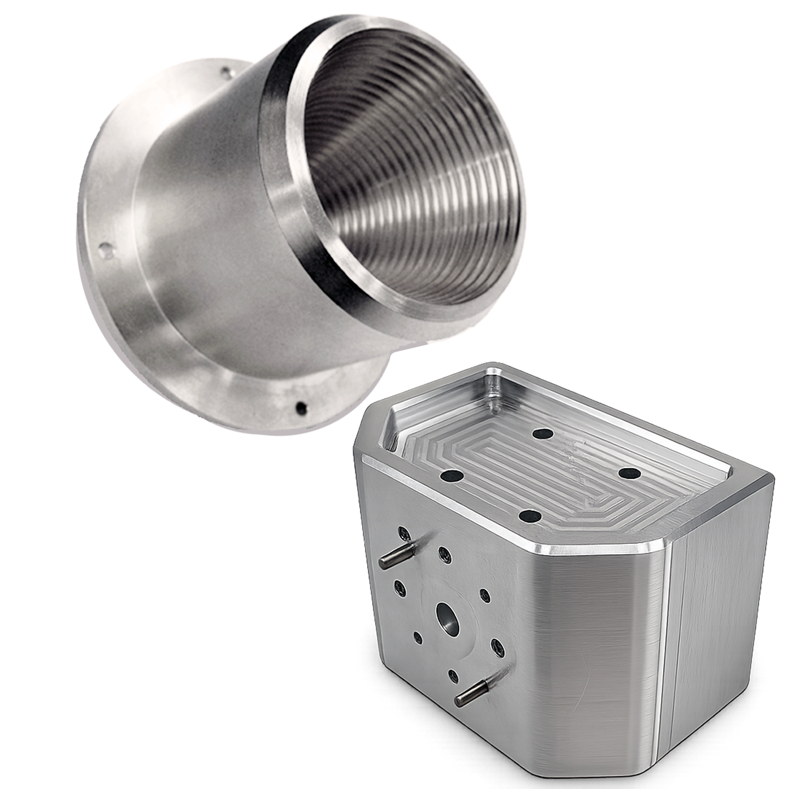
| Model | Band | Frequency Range | Gain | 3 dB Beamwidth, E-Plane | 3 dB Beamwidth, H-Plane | Polarization | VSWR | RF Port |
|---|---|---|---|---|---|---|---|---|
| 268X-XX/39-DP-VH | X-Band | 8.2–12.4 GHz | 15 dB | 22° | 26° | Vertical / Horizontal | 1.5:1 | WR-90 Waveguide, UG-39/U Flange |
| 268Ku-XX/419-DP-VH | Ku-Band | 12.4–18 GHz | 15 dB | 22° | 26° | Vertical / Horizontal | 1.5:1 | WR-62 Waveguide, UG-419/U Flange |
| 268K-XX/595-DP-VH | K-Band | 18–26.5 GHz | 15 dB | 22° | 26° | Vertical / Horizontal | 1.5:1 | WR-42 Waveguide, UG-595/U Flange |
| 268A-XX/599-DP-VH | Ka-Band | 26.5–40 GHz | 15 dB | 22° | 26° | Vertical / Horizontal | 1.5:1 | WR-28 Waveguide, UG-599/U Flange |
| 268B-XX/383-DP-VH | Q-Band | 33–50 GHz | 15 dB | 22° | 26° | Vertical / Horizontal | 1.5:1 | WR-22 Waveguide, UG-383/U Flange |
| 268U-XX/383-DP-VH | U-Band | 40–60 GHz | 15 dB | 22° | 26° | Vertical / Horizontal | 1.5:1 | WR-19 Waveguide, UG-383/U-M Flange |
| 268V-XX/385-DP-VH | V-Band | 50–75 GHz | 15 dB | 22° | 26° | Vertical / Horizontal | 1.5:1 | WR-15 Waveguide, UG-385/U-M Flange |
| 268E-XX/387-DP-VH | E-Band | 60–90 GHz | 15 dB | 22° | 26° | Vertical / Horizontal | 1.5:1 | WR-12 Waveguide, UG-387/U Flange |
| 268W-XX/387-DP-VH | W-Band | 75–110 GHz | 15 dB | 22° | 26° | Vertical / Horizontal | 1.5:1 | WR-10 Waveguide, UG-387/U-M Flange |
*Dual-polarized antenna configurations, pipe dimensions, and bandwidth may be limited based on frequency and application requirements. Please contact Mi-Wave to discuss a solution tailored to your specific needs.
*All data presented is collected from a sample lot.
* Actual data may vary unit to unit, slightly.
*All testing was performed under +25 °C case temperature.
*Consult factory to confirm if material, plating, size, shape, orientation and any electrical parameter is critical for the application as website information is for reference only.
*Millimeter Wave Products, Inc. reserves the right to change the information presented on website without notice as we continue to enhance the performance and design of our products.
*Consult factory to confirm if material, plating, size, shape, orientation and any electrical parameter is critical for the application as website information is for reference only.
*Millimeter Wave Products, Inc. reserves the right to change the information presented on website without notice as we continue to enhance the performance and design of our products.
Key Features & Performance Benefits
Wideband Frequency Coverage (8.4–220 GHz)
Supports RF, microwave, and millimeter-wave systems across a broad frequency range, reducing the need for multiple antennas in multi-band environments.
Scalar Feed Optimization for Improved Performance
Incorporates scalar feed structures to enhance radiation efficiency, reduce edge diffraction, and improve overall antenna performance.
Low VSWR and Broadband Impedance Matching
Provides excellent impedance matching across wide frequency ranges, minimizing reflections and maximizing power transfer.
Stable Phase Center
Maintains a consistent phase center across frequency, which is critical for reflector feed applications and precision measurement systems.
Symmetrical Radiation Patterns
Designed to produce clean, symmetrical beam patterns with low sidelobes for accurate signal transmission and reception.
Consistent Gain Across Frequency
Delivers predictable and stable gain performance, supporting reliable system operation and repeatable measurement results.
Controlled Illumination for Reflector Systems
Ideal for feeding parabolic and offset reflectors, ensuring proper illumination and improved aperture efficiency.
Low Sidelobe Levels
Reduces unwanted radiation outside the main beam, improving signal quality and minimizing interference.
Precision Machined Construction
Manufactured using high-precision processes to ensure repeatable electrical performance and mechanical durability.
Flexible Integration Options
Available with standard waveguide interfaces for easy integration into RF systems, test setups, and instrumentation.
Custom Engineering Available
Supports custom frequency ranges, polarization options, mechanical configurations, and system-specific designs.
Scalar Feed Horn Antennas
Mi-Wave’s Series 268 Scalar Feed Horn Antennas are precision-engineered wideband antennas that combine the broadband response of horn antennas with scalar feed tuning to deliver smooth radiation patterns, low VSWR, and excellent phase center stability across broad frequency ranges.
The Series 268 design is optimized to provide consistent gain, predictable beam symmetry, and reliable directivity in demanding RF, microwave, and millimeter-wave systems. These antennas are ideal for engineers seeking stable performance across communications, radar, test, and measurement applications.
Controls aperture illumination, improves beam symmetry, and helps stabilize phase center performance.
RF Energy Enters the Feed
The antenna receives RF energy through a waveguide interface and guides it into the scalar feed horn structure.
Scalar Geometry Shapes the Fields
The scalar feed structure helps control the electromagnetic field distribution across the aperture for smoother beam behavior.
Stable Phase Center
Scalar feed tuning helps maintain phase center stability across frequency, improving repeatability in measurement and antenna systems.
Predictable Beam Symmetry
The horn radiates a smooth, symmetrical beam pattern with reliable directivity and controlled sidelobe behavior.
Low VSWR Performance
Proper scalar feed design supports improved impedance matching and helps reduce reflections across the operating band.
Wideband System Integration
Series 268 antennas are suited for laboratory environments, field deployments, and direct integration into RF subsystems or instrumentation.
Why Scalar Feed Horn Design Matters
Smooth Radiation Patterns
Scalar feed tuning helps produce consistent, symmetrical beam performance across broad frequency ranges.
Stable Phase Center
Improved phase center stability supports repeatable measurements and reliable antenna alignment.
Low VSWR
Careful feed geometry helps maintain good impedance matching and reduce reflected power.
Custom Antenna Solutions
Mi-Wave develops custom antenna designs for specific frequency bands, performance targets, and system requirements.
Scalar Feed Horn Antenna Engineering Calculators
These RF engineering calculators help estimate antenna performance for scalar feed horn antennas, including reflector feed systems, communications platforms, radar systems, antenna measurement ranges, and microwave and millimeter-wave test environments. Use them to calculate antenna gain, beamwidth, aperture size required for target gain, effective aperture, free-space path loss, and wavelength across RF, microwave, and millimeter-wave frequencies.
Scalar feed horn antennas are designed for stable phase center performance, low VSWR, smooth radiation patterns, and controlled reflector illumination. A typical starting efficiency range for many systems is 0.50 to 0.75.
Antenna Gain Calculator
Antenna Gain (dBi):
Antenna Beamwidth Calculator
Aperture Size Required for Target Gain
Antenna Effective Aperture Calculator
Effective Aperture (m²):
Free Space Path Loss Calculator
RF Wavelength Calculator
Wavelength (mm):
Applications
Scalar Feed Horn Antenna Applications
Mi-Wave Scalar Feed Horn Antennas are used in RF, microwave, and millimeter-wave systems requiring stable radiation patterns, low VSWR, controlled illumination, and precise phase center performance.
Reflector Antenna Feed Systems
Widely used as feed antennas for reflector systems requiring accurate illumination and efficiency optimization.
Typical applications include:
- Parabolic reflector antennas
- Cassegrain antenna systems
- Offset reflector configurations
- High-gain antenna systems
- Satellite communication terminals
Antenna Measurement and Calibration
Used in precision environments where repeatability and measurement accuracy are critical.
Typical applications include:
- Antenna gain and pattern measurements
- Near-field and far-field testing
- Calibration reference antennas
- Beam characterization
- RF system validation
RF Test & Measurement Systems
Supports laboratory and production environments requiring stable and predictable RF performance.
Typical applications include:
- RF subsystem testing
- Component characterization
- Instrumentation integration
- Signal integrity analysis
- Broadband measurement setups
Communications Systems
Used in systems requiring controlled radiation patterns and reliable signal transmission.
Typical applications include:
- Microwave communication links
- Millimeter-wave communication systems
- Experimental communication platforms
- Ground station development
- Multi-band communication systems
Radar Systems
Supports radar applications requiring precise beam control and consistent performance.
Typical applications include:
- Radar calibration
- FMCW and pulse radar systems
- Target detection experiments
- Radar system validation
- High-frequency sensing
Research and Development (R&D)
Widely used in research environments for advanced RF system development and testing.
Typical applications include:
- Academic research
- Government laboratories
- Prototype system validation
- Electromagnetic studies
- Antenna design research
Frequently Asked Questions (FAQ)
What is a scalar feed horn antenna?
A scalar feed horn antenna is a horn antenna that incorporates scalar feed structures to improve radiation characteristics, reduce sidelobes, and provide better impedance matching.
What are scalar feed horn antennas used for?
They are used in applications requiring stable radiation patterns, low VSWR, and precise reflector illumination, such as antenna measurement, radar systems, and communications.
What frequency range do Mi-Wave scalar feed horn antennas support?
Mi-Wave Series 268 antennas operate from 8.4 GHz to 220 GHz.
What makes scalar feed horns different from standard horn antennas?
Scalar feed horns use additional structural features to improve beam symmetry, impedance matching, and sidelobe suppression, resulting in more controlled radiation patterns.
Why are scalar feed horns used in reflector systems?
They provide controlled illumination and stable phase center performance, improving reflector efficiency and overall antenna performance.
Do scalar feed horn antennas have low VSWR?
Yes. They are designed for excellent impedance matching, resulting in low VSWR across wide frequency ranges.
Are scalar feed horn antennas suitable for antenna testing?
Yes. Their repeatability, symmetry, and stable performance make them ideal for antenna measurement and calibration.
What type of polarization do scalar feed horn antennas support?
They typically support linear polarization, with consistent polarization characteristics across frequency.
Can scalar feed horns be used at millimeter-wave frequencies?
Yes. They are designed for operation across microwave and millimeter-wave frequency ranges.
Can Mi-Wave scalar feed horn antennas be customized?
Yes. Custom designs are available for frequency bands, waveguide interfaces, polarization, and mechanical configurations.
Glossary of Prime Focus Antenna Terms
This glossary defines terminology related to prime focus reflector antennas used in RF, microwave, and millimeter-wave systems. These antennas are commonly deployed in satellite communications, radar systems, antenna measurement ranges, RF laboratories, EMC testing facilities, and millimeter-wave research platforms where high gain, controlled beam patterns, and predictable antenna performance are required.
Reflector Antenna Fundamentals
Prime Focus Antenna
A parabolic reflector antenna configuration where the feed antenna is located at the geometric focal point of the reflector. Incoming RF energy reflects from the parabolic surface and concentrates at the feed, producing high gain and directional radiation patterns.
Parabolic Reflector
A curved reflective surface shaped as a paraboloid that focuses electromagnetic waves toward a focal point. Parabolic reflectors are widely used in satellite communications, radar, and antenna testing applications.
Reflector Diameter
The physical width of the antenna dish. Larger reflector diameters produce higher gain and narrower beamwidth.
Reflector Aperture
The opening area of the antenna reflector that captures or radiates RF energy.
Reflector Surface Accuracy
The precision with which the reflector surface matches the ideal parabolic geometry. High surface accuracy is essential for high-frequency microwave and millimeter-wave antennas.
Reflector Rim
The outer edge of the antenna dish that defines the physical boundary of the reflector aperture.
Reflector Offset
A reflector configuration where the feed is offset from the center of the dish to eliminate feed blockage and improve efficiency.
Cassegrain Antenna
A dual-reflector antenna design that uses both a main reflector and a secondary subreflector to improve feed placement and system efficiency.
Feed System Terms
Feed Antenna
The antenna element located at the focal point that transmits RF energy toward the reflector or receives signals reflected from the dish.
Horn Antenna Feed
A waveguide-based feed antenna commonly used with reflector antennas due to its controlled radiation pattern and broadband performance.
Feed Support Structure
Mechanical supports that position the feed antenna at the focal point of the reflector.
Feed Illumination Pattern
The RF energy distribution produced by the feed antenna across the reflector surface.
Edge Taper
The reduction of feed illumination near the edge of the reflector to reduce sidelobes and spillover losses.
Feed Blockage
Signal loss caused when the feed antenna and support structure partially block the reflector aperture.
Spillover
RF energy from the feed antenna that misses the reflector surface.
Antenna Radiation Characteristics
Antenna Gain
A measure of how effectively an antenna directs RF energy in a specific direction relative to an isotropic radiator.
Directivity
A measure of how concentrated an antenna’s radiation pattern is toward the main beam.
Beamwidth
The angular width of the main radiation lobe of an antenna.
Half-Power Beamwidth (HPBW)
The angular separation between points where antenna gain drops by 3 dB from its peak value.
Main Lobe
The region of maximum radiation in an antenna pattern.
Sidelobes
Secondary radiation lobes outside the main beam.
Back Lobe
Radiation emitted behind the antenna opposite the main beam direction.
Radiation Pattern
A graphical representation of the distribution of RF energy around an antenna.
Antenna Pattern Symmetry
The degree to which the radiation pattern is uniform across azimuth and elevation.
Antenna Geometry and Alignment
Focal Point
The location where reflected RF energy converges after striking the parabolic reflector.
Focal Length
The distance from the reflector surface to the focal point.
F/D Ratio
The ratio between focal length and reflector diameter. This value influences feed design and reflector illumination.
Antenna Alignment
The process of orienting the antenna so that the main beam points toward the desired signal source.
Pointing Accuracy
The precision with which the antenna can be directed toward a specific target.
Pointing Loss
Signal loss caused by antenna misalignment relative to the desired direction.
Antenna Efficiency and Performance
Antenna Efficiency
The percentage of input RF power effectively radiated or received by the antenna.
Aperture Efficiency
The ratio of effective antenna aperture to physical reflector area.
Effective Aperture
The area over which an antenna collects electromagnetic energy.
Surface Loss
Losses caused by imperfections or resistive effects on the reflector surface.
Ohmic Loss
Signal loss caused by resistance in conductive materials.
Antenna Gain-to-Diameter Ratio
A measure of gain achieved for a given reflector size.
RF Measurement and Testing Terms
Antenna Measurement Range
A facility designed to measure antenna characteristics such as gain, radiation pattern, polarization, and sidelobe levels.
Near-Field Region
The region close to an antenna where electromagnetic fields are complex and not fully formed.
Far-Field Region
The region where electromagnetic waves behave as plane waves and antenna radiation patterns become stable.
Compact Antenna Test Range (CATR)
A specialized measurement system that simulates far-field conditions within a confined space.
Antenna Calibration
The process of verifying antenna performance against known reference standards.
Reference Antenna
A calibrated antenna used to measure gain or radiation patterns of other antennas.
RF Frequency and Signal Terms
Radio Frequency (RF)
Electromagnetic frequencies used for wireless communication and sensing.
Microwave Frequencies
RF frequencies typically ranging from 1 GHz to 30 GHz.
Millimeter-Wave (mmWave)
Frequencies ranging from 30 GHz to 300 GHz, used in advanced communication and radar systems.
Wavelength
The physical distance between repeating peaks of an electromagnetic wave.
Frequency
The number of cycles per second of an electromagnetic wave.
Satellite Communication and Radar Applications
Satellite Communications (SatCom)
Communication systems that use orbiting satellites to relay RF signals between ground stations.
Ground Station Antenna
A high-gain antenna used for communication with satellites.
Uplink
Transmission of RF signals from Earth to a satellite.
Downlink
Transmission of RF signals from a satellite to Earth.
Radar Antenna
An antenna used to transmit RF signals and receive reflected signals for target detection.
Radar Cross Section (RCS)
A measure of how detectable an object is by radar.
Tracking Antenna
An antenna system capable of continuously pointing toward a moving satellite or object.
Frequency Bands Used with Reflector Antennas
L-Band — 1–2 GHz
S-Band — 2–4 GHz
C-Band — 4–8 GHz
X-Band — 8–12 GHz
Ku-Band — 12–18 GHz
Ka-Band — 26–40 GHz
Q-Band — 33–50 GHz
V-Band — 50–75 GHz
W-Band — 75–110 GHz
These frequency bands are widely used in satellite communications, radar systems, wireless networks, and millimeter-wave research applications.
Interested in this product or other Mi-Wave solutions?
Contact our team to discuss your frequency range, interface needs, and application requirements.
Custom configurations are available for specialized RF, microwave, and millimeter-wave systems.
Return to Dual Polarized Antennas
Return to Antennas
Return to Products Page
