

Products> Antenna Products > Linear to Circular Polarizers
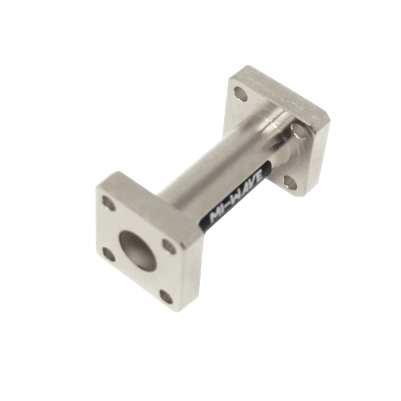
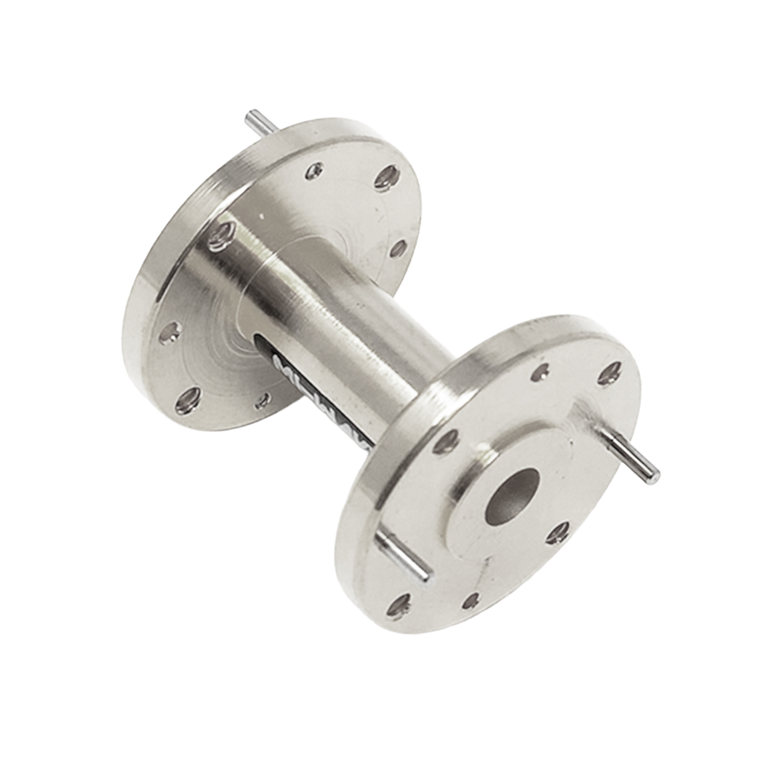
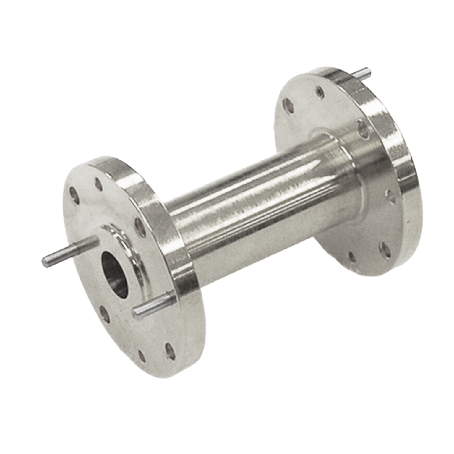
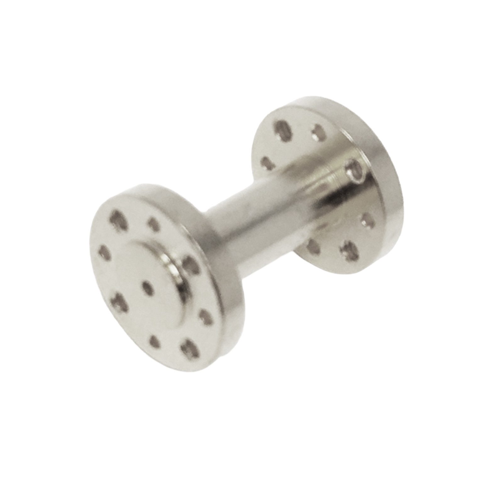
Mi-Wave’s Series 282 Linear to Circular Polarizers are precision-engineered waveguide components designed to convert linearly polarized RF signals into circularly polarized signals with high polarization purity, low insertion loss, and stable broadband performance across microwave and millimeter-wave frequency bands.
These polarizers are commonly integrated into antenna systems requiring Right-Hand Circular Polarization (RHCP) or Left-Hand Circular Polarization (LHCP) operation, particularly in satellite communications, radar systems, telemetry links, and advanced RF research environments where polarization integrity is critical to system performance.
The Series 282 operates by introducing a controlled phase shift between two orthogonal electromagnetic field components within the waveguide structure. By precisely manipulating the phase relationship between the orthogonal modes, the polarizer converts a linearly polarized signal into a circularly polarized waveform while maintaining low VSWR and minimal signal degradation.
Circular polarization provides several advantages in high-frequency RF systems, including reduced sensitivity to antenna orientation, improved polarization matching between transmit and receive systems, reduced multipath fading effects, and more reliable signal performance in dynamic or mobile environments.
Series 282 polarizers are commonly integrated with reflector antennas, conical horn antennas, scalar feed systems, horn lens antennas, and OMT-based antenna architectures to create fully optimized circularly polarized antenna systems.
The standard models shown represent only part of Mi-Wave’s broader product capabilities. Custom configurations are available to support specific frequency bands, interfaces, and application requirements, enabling optimized solutions for specialized RF, microwave, and millimeter-wave systems.
| Model | Circular Antenna Port Internal Diameter (inches) (.XXX in Model No.) | Frequency (GHz) | Flange | Insertion Loss (dB) typical | Bandwidth (GHz) | Axial Ratio (dB) | LINK |
|---|---|---|---|---|---|---|---|
| 282X-XX/.XXX/90 | Option 1 1.094" ID Circular Waveguide Option 2 .938" ID Circular Waveguide Option 3 .797" ID Circular Waveguide | 8-9.97 8.5-11.6 9.7-12.4 | UG-39/U | 1 | 2 | 1 | |
| 282Ku-XX/.XXX/90 | Option 1 .660" ID Circular Waveguide Option 2 .550" ID Circular Waveguide | 12.4-14.6 14.6-17.5 | UG-419/U | 1 | 2.2 | 1 | |
| 282K-XX/.XXX/595 | Option 1 .470" ID Circular Waveguide Option 2 .396" ID Circular Waveguide Option 3 .328" ID Circular Waveguide | 17.5- 20.5 20.5-24.5 24.5-26.5 | UG-595/U | 1 | 3 | 1 | |
| 282A-XX/.XXX/599 | Option 1 .328" ID Circular Waveguide Option 2 .281" ID Circular Waveguide Option 3 .250" ID Circular Waveguide Option 4 .219" ID Circular Waveguide | 26.5-28.5 28.5-33 33-38.5 38.5-40 | UG-599/U | 1 | 5 | 1 | |
| 282B-XX/.XXX/383 | Option 1 .250" ID Circular Waveguide Option 2 .219" ID Circular Waveguide Option 3 .188" ID Circular Waveguide | 33.0-38.5 38.5-43.0 43.0-50.0 | UG-383/U | 1 | 5 | 1 | |
| 282U-XX/.XXX/383 | Option 1 .219" ID Circular Waveguide Option 2 .188" ID Circular Waveguide Option 3 .165" ID Circular Waveguide Option 4 .141" ID Circular Waveguide | 40-43 43-50 50-58 58-60 | UG-383/U-M | 1 | 6 | 1 | |
| 282V-XX/.XXX/385 | Option 1 .165" ID Circular Waveguide Option 2 .141" ID Circular Waveguide Option 3 .125" ID Circular Waveguide | 50-58 58-68 68-75 | UG-385/U | 1 | 7 | 1 | |
| 282E-XX/.XXX/387 | Option 1 .141" ID Circular Waveguide Option 2 .125" ID Circular Waveguide Option 3 .110" ID Circular Waveguide Option 4 .094" ID Circular Waveguide | 60-68 68-77 77-87 87-90 | UG-387/U | 1 | 7 | 1 | |
| 282W-XX/.XXX/387 | Option 1 .125" ID Circular Waveguide Option 2 .110" ID Circular Waveguide Option 3 .094" ID Circular Waveguide Option 4 .082" ID Circular Waveguide | 75-77 77-87 87-100 100-110 | UG-387/U-M | 1 | 8 | 1 | |
| 282F-XX/.XXX/38 | Option 1 .094" ID Circular Waveguide Option 2 .082" ID Circular Waveguide Option 3 .075" ID Circular Waveguide Option 4 .067" ID Circular Waveguide | 90-100 100-112 112-125 125-140 | UG-387/U-M | 1 | 10 | 1 | |
| 282D-XX/.XXX/387 | Option 1 .082" ID Circular Waveguide Option 2 .075" ID Circular Waveguide Option 3 .067" ID Circular Waveguide Option 4 .059" ID Circular Waveguide | 110-112 112-125 125-140 140-170 | UG-387/U-M | 1.5 | 10 | 1 | |
| 282G-XX/.XXX/387 | Option 1 .067" ID Circular Waveguide Option 2 .059" ID Circular Waveguide | 125-140 140-220 | UG-387/U-M | 1.7 | 10 | 1 |
*All data presented is collected from a sample lot.
* Actual data may vary unit to unit, slightly.
*All testing was performed under +25 °C case temperature.
*Consult factory to confirm if material, plating, size, shape, orientation and any electrical parameter is critical for the application as website information is for reference only.
*Millimeter Wave Products, Inc. reserves the right to change the information presented on website without notice as we continue to enhance the performance and design of our products.
Linear to Circular Polarizer Engineering Calculators
These RF engineering calculators help estimate supporting parameters for linear to circular polarizers, including wavelength, free-space path loss, phase shift timing, and axial ratio relationships used in microwave and millimeter-wave systems. Use them for SatCom, radar, RF link design, and laboratory test applications.
RF Wavelength Calculator
Wavelength (mm):
Free Space Path Loss Calculator
Quarter-Wave Phase Shift Length
Quarter-Wave Length (mm):
Phase Shift Time Delay
Quarter-Cycle Delay (ps):
Axial Ratio Converter
Axial Ratio dB Converter
Key Features & Performance Benefits
Linear-to-Circular Polarization Conversion
Converts linearly polarized RF energy into circularly polarized output using a controlled phase relationship between orthogonal field components. This supports reliable polarization conversion in high-frequency systems.
Wide Frequency Coverage (12–220 GHz)
Supports microwave through millimeter-wave applications across multiple standard bands, enabling flexible integration into diverse RF system architectures.
RHCP or LHCP Configurations
Available in Right-Hand Circular Polarization or Left-Hand Circular Polarization versions to match system requirements and polarization conventions.
Improved Orientation Tolerance
Circular polarization reduces sensitivity to antenna orientation, improving link robustness in systems where alignment may vary.
Reduced Polarization Mismatch Loss
Helps minimize losses caused by polarization misalignment between transmitting and receiving antennas, improving effective signal transfer.
Helps Mitigate Multipath Effects
Circular polarization can reduce the impact of reflections and polarization distortion in complex propagation environments.
Stable Axial Ratio Performance
Designed for tight polarization control across the operating band, supporting consistent circular polarization quality. Mi-Wave literature cites axial ratio < 1.0 dB over the indicated bandwidth for its Series 282 solutions.
Low VSWR and Low Reflection
Engineered for low reflection and good impedance matching, supporting stable RF system performance. Mi-Wave highlights low reflection and tight phase balance on its current polarizer page.
Standard Waveguide Integration
Designed to integrate with standard waveguide interfaces, simplifying installation into existing RF, microwave, and millimeter-wave systems.
Custom Polarizer Solutions Available
Custom designs are available for specific frequency ranges, bandwidths, interfaces, and polarization requirements.
Applications
Mi-Wave Linear to Circular Polarizers are used in RF, microwave, and millimeter-wave systems that require stable polarization conversion, reduced mismatch sensitivity, and reliable circularly polarized operation. These components are especially valuable in applications where antenna alignment, polarization purity, and link robustness are critical.
Satellite Communications (SatCom)
Linear-to-circular polarizers are widely used in satellite communication systems where circular polarization is preferred for reliable uplink and downlink performance.
Typical SatCom applications include:
- Satellite ground terminals
- Uplink and downlink polarization conversion
- Feeder link and gateway systems
- Reflector-fed SatCom antennas
- Experimental and research satellite links
These polarizers help improve signal consistency by reducing sensitivity to relative antenna orientation and polarization mismatch.
Radar Systems
Polarizers are used in radar systems that benefit from circular polarization for target illumination, signal discrimination, and system integration.
Typical radar applications include:
- Polarization-controlled radar feeds
- Experimental radar systems
- Reflector-fed radar antennas
- Radar calibration and verification setups
- Microwave and millimeter-wave radar research
RF Links and Point-to-Point Systems
In RF link applications, polarization conversion components support systems where circular polarization improves reliability or compatibility with existing antenna architectures.
Typical RF link applications include:
- Microwave relay systems
- Millimeter-wave RF links
- Specialized point-to-point communications
- Broadband link experiments
- Custom RF subsystem integration
Antenna Measurement and Test Systems
Linear-to-circular polarizers are also useful in test environments where known circular polarization states are required for repeatable measurement and characterization.
Typical test applications include:
- Antenna characterization
- Polarization verification
- RF subsystem testing
- Calibration setups
- Laboratory research platforms
Research and Development
These polarizers support advanced R&D efforts in government, academic, defense, and commercial environments.
Typical research applications include:
- Polarization studies
- High-frequency propagation experiments
- RF subsystem prototyping
- Antenna and feed development
- Millimeter-wave system research
Frequently Asked Questions (FAQ)
What is a linear to circular polarizer?
A linear to circular polarizer is an RF component that converts a linearly polarized signal into a circularly polarized signal by introducing a controlled phase shift between two orthogonal field components.
What are linear to circular polarizers used for?
They are used in satellite communications, radar systems, RF links, and test environments where circular polarization improves system compatibility, link stability, and polarization control.
What frequency range do Mi-Wave linear to circular polarizers support?
Mi-Wave’s current linear-to-circular polarizer offerings span 12 GHz to 220 GHz.
What is the difference between RHCP and LHCP?
RHCP stands for Right-Hand Circular Polarization and LHCP stands for Left-Hand Circular Polarization. The difference is the direction in which the electric field rotates as the wave propagates.
Why use circular polarization in RF systems?
Circular polarization can reduce sensitivity to antenna orientation, reduce mismatch loss, and help mitigate multipath effects in some environments.
How does a linear to circular polarizer work?
It creates a defined phase offset between orthogonal signal components so the output electric field rotates and forms a circularly polarized wave.
Are these polarizers compatible with standard waveguide systems?
Yes. Mi-Wave’s polarizers are designed for integration with standard waveguide interfaces.
Do Mi-Wave polarizers support custom requirements?
Yes. Mi-Wave offers custom configurations for frequency band, bandwidth, interface, and polarization requirements.
What performance metrics matter most in a circular polarizer?
Important parameters include axial ratio, VSWR, phase balance, insertion loss, bandwidth, and polarization sense. Mi-Wave highlights tight axial ratio control, low reflection, and stable polarization characteristics.
Are linear to circular polarizers suitable for millimeter-wave systems?
Yes. Mi-Wave offers solutions well into the millimeter-wave region, including D-Band and G-Band examples.
Polarization Fundamentals
Linear Polarization
A polarization state in which the electric field remains in a single fixed plane as the electromagnetic wave propagates.
Circular Polarization
A polarization state in which the electric field rotates as the wave propagates, forming a circular pattern over time. Circular polarization is often used to reduce sensitivity to antenna orientation and polarization mismatch.
Right-Hand Circular Polarization (RHCP)
A circular polarization state in which the electric field rotates in the right-hand sense relative to the direction of propagation.
Left-Hand Circular Polarization (LHCP)
A circular polarization state in which the electric field rotates in the left-hand sense relative to the direction of propagation.
Polarization Conversion
The process of transforming one polarization state into another, such as converting a linearly polarized signal into a circularly polarized signal.
Polarization Sense
The rotational direction of a circularly polarized wave, identified as either RHCP or LHCP.
Polarization Mismatch
Signal loss that occurs when the transmitting and receiving antennas use different or incompatible polarization states.
Cross-Polarization
An unwanted polarization component orthogonal to the desired polarization, which can reduce signal quality and system performance.
Polarization Purity
A measure of how closely a signal maintains the intended polarization state without undesired components.
Polarizer and Wave Concepts
Linear to Circular Polarizer
An RF component designed to convert a linearly polarized input signal into a circularly polarized output signal by establishing the correct amplitude and phase relationship between orthogonal field components.
Orthogonal Field Components
Two perpendicular electric field components that combine to form a circularly polarized wave when equal in amplitude and 90 degrees out of phase.
Phase Shift
The relative phase difference between signal components. In linear-to-circular conversion, a 90-degree phase shift is required between orthogonal field components.
Phase Balance
The accuracy of the intended phase relationship between orthogonal signal components. Good phase balance is essential for achieving high-quality circular polarization.
Amplitude Balance
The degree to which the orthogonal field components have equal amplitude. Unequal amplitudes can degrade axial ratio and polarization quality.
Quarter-Wave Relationship
A phase relationship equivalent to 90 electrical degrees, often used in polarization conversion and waveguide phase control.
Propagation Direction
The direction in which the electromagnetic wave travels, used as the reference for defining RHCP and LHCP.
Wavefront Rotation
The rotation of the electric field vector over time in a circularly polarized wave.
Electrical Performance Terms
Axial Ratio
A measure of circular polarization quality. It is the ratio of the major axis to the minor axis of the polarization ellipse. Lower axial ratio indicates polarization closer to ideal circular.
Axial Ratio (dB)
The axial ratio expressed in decibels. Values closer to 0 dB indicate better circular polarization performance.
Insertion Loss
The reduction in signal power caused by inserting the polarizer into the RF path.
VSWR (Voltage Standing Wave Ratio)
A measure of impedance matching between the polarizer and the transmission system. Lower VSWR indicates better matching and lower reflection.
Return Loss
The amount of signal reflected back toward the source due to impedance mismatch.
Reflection
RF energy that is not transmitted through the component and is instead reflected back into the system.
Bandwidth
The range of frequencies over which the polarizer maintains acceptable performance for parameters such as axial ratio, VSWR, and insertion loss.
Phase Stability
The ability of the polarizer to maintain the required phase relationship across frequency or environmental changes.
Amplitude Stability
The consistency of signal magnitude balance across the operating band.
Electrical Performance
The combined RF behavior of the component, including loss, match, phase response, bandwidth, and polarization conversion quality.
RF and Frequency Terms
Radio Frequency (RF)
Electromagnetic frequencies used for communication, radar, sensing, and test systems.
Microwave Frequencies
Typically frequencies from 1 GHz to 30 GHz.
Millimeter-Wave (mmWave)
Typically frequencies from 30 GHz to 300 GHz.
Frequency Band
A defined portion of the RF spectrum used for a particular system or application.
Operating Frequency Range
The span of frequencies over which the polarizer is designed to function properly.
Wavelength
The physical distance between repeating points of an electromagnetic wave.
Electrical Length
The phase-related length of a structure relative to the wavelength of the signal.
Waveguide and Interface Terms
Waveguide
A metallic transmission structure used to guide RF energy, especially at microwave and millimeter-wave frequencies.
Waveguide Polarizer
A polarizer integrated into a waveguide structure to perform polarization conversion while maintaining controlled RF transmission.
Waveguide Interface
The electrical and mechanical format used to connect the polarizer into a waveguide system.
Flange
A standardized connection surface used to join waveguide components together.
Standard Waveguide Interface
A commonly used waveguide size and flange format that allows straightforward integration into existing RF systems.
Mode
The electromagnetic field distribution within a waveguide. Polarizer design must account for proper mode control to ensure stable performance.
Cutoff Frequency
The minimum frequency at which a given waveguide mode can propagate.
Transition Section
A structural region that guides energy between two RF geometries or polarization states.
Antenna and System Terms
Antenna Feed System
The RF path and components that deliver energy to an antenna, often including waveguides, polarizers, OMTs, and feed horns.
Reflector Feed System
A feed arrangement used with parabolic or offset reflectors where polarization control is often critical for performance.
Satellite Communications (SatCom)
Communication systems that relay RF signals via satellites, commonly using circular polarization for robust operation.
Radar System
A system that transmits and receives RF energy for detection, tracking, ranging, or sensing.
RF Link
A signal path between transmitting and receiving points in a wireless system.
Laboratory Test Environment
A controlled RF setup used to evaluate component, subsystem, and antenna performance.
Polarization Isolation
The degree to which one polarization is separated from another, helping reduce interference and improve signal discrimination.
Orientation Sensitivity
The extent to which system performance depends on the angular alignment of antennas. Circular polarization can reduce this sensitivity.
Multipath Effects
Signal distortions caused by reflections that create multiple propagation paths between transmitter and receiver.
Performance and Design Considerations
Orientation Tolerance
The ability of a system to maintain performance despite relative antenna rotation or misalignment.
Signal Robustness
The ability of the RF link to maintain performance in practical operating conditions.
System Integration
The process of incorporating a polarizer into a complete RF, microwave, or millimeter-wave assembly.
Mechanical Tolerance
The allowable dimensional variation in the physical construction of the component.
Precision Machining
High-accuracy manufacturing used to ensure repeatable RF performance at microwave and millimeter-wave frequencies.
Thermal Stability
The ability of the component to maintain performance across temperature changes.
Repeatable Performance
Consistent RF behavior from unit to unit and across operating conditions.
Custom Configuration
A design tailored to specific frequency bands, bandwidths, interfaces, or polarization requirements.
Common Engineering Concepts
90-Degree Phase Difference
The phase offset required between equal orthogonal components to generate ideal circular polarization.
Equal Amplitude Condition
A requirement for ideal circular polarization in which the orthogonal field components have the same magnitude.
Polarization Ellipse
A general representation of polarization state. Circular polarization is a special case where the ellipse becomes a circle.
Elliptical Polarization
A polarization state that occurs when orthogonal components are unequal in amplitude or not exactly 90 degrees out of phase.
Mismatch Loss
Power loss caused by impedance mismatch or polarization mismatch within a system.
Link Performance
The overall behavior of an RF transmission path, including loss, polarization compatibility, and signal quality.
Applications and Use Cases
Satellite Ground Terminal
A terrestrial RF system used to communicate with satellites, often benefiting from circular polarization.
Reflector Antenna System
An antenna configuration using a shaped reflector and feed system, often requiring tight polarization control.
RF Test System
A setup used to measure and validate RF component performance.
Polarization Measurement
The process of characterizing the polarization state of an RF signal or antenna system.
Radar Feed Network
The RF path that delivers energy into a radar antenna structure, where polarization conversion may be required.
Microwave Link System
A communication system operating in microwave frequencies where polarization compatibility affects link quality.
Why Choose Mi-Wave
Mi-Wave is a trusted manufacturer of microwave and millimeter-wave RF components, supporting commercial, government, and research systems worldwide. Our linear to circular polarizers are designed and manufactured with careful attention to phase balance, axial ratio performance, and low reflection, ensuring reliable polarization conversion across the operating band.
Engineering-Driven Performance
Each polarizer is optimized to deliver tight axial ratio control, stable polarization characteristics, and low VSWR, supporting consistent system behavior in demanding RF environments.
Broad Frequency Expertise
Mi-Wave supports polarization conversion solutions across microwave through millimeter-wave frequencies, enabling integration into a wide range of RF system architectures.
Custom Polarizer Solutions
Custom designs are available to support specific frequency ranges, bandwidths, waveguide interfaces, and polarization requirements. Mi-Wave’s sales engineering team works directly with customers to ensure proper system integration.
What This Product Does
Linear-to-Circular Polarization Conversion
Linear to circular polarizers operate by introducing a controlled phase shift between two orthogonal components of an incoming linearly polarized RF signal. This phase relationship causes the electric field to rotate as the wave propagates, producing a circularly polarized output.
This conversion enables improved link reliability in systems where antenna orientation varies or where circular polarization is required for proper transmit and receive operation. The result is improved signal integrity, reduced polarization loss, and more robust RF system performance.
Typical Uses and Applications
-
Satellite communication systems
-
RF and microwave communication links
-
Radar and sensing systems
-
Antenna and polarization testing
-
RF and millimeter-wave test laboratories
-
System integration and validation environments
Key Features
-
Converts linear polarization to circular polarization
-
Available in RHCP or LHCP configurations
-
Low axial ratio across the operating bandwidth
-
Low VSWR for minimal signal reflection
-
Suitable for microwave and millimeter-wave frequencies
-
Precision mechanical construction for repeatable performance
-
Compatible with standard circular waveguide interfaces
-
Custom configurations available