

Mi-Wave’s H-Plane Waveguide Bends are high-precision transmission components designed to provide accurate directional changes and offsets in microwave and millimeter-wave systems. Available in the 670, 671, 672, and 675 Series, these bends are manufactured as precision waveguide sections shaped to standard angles of 30°, 45°, 60°, and 90°.
H-plane bends redirect RF energy in the magnetic field plane (H-plane) of the waveguide, allowing efficient routing of signals through compact assemblies, test systems, and integrated RF subsystems. Manufactured to rigid specifications, these components are designed to minimize detrimental effects on overall system VSWR and maintain reliable waveguide performance.
Mi-Wave H-Plane Bends are available in a wide range of frequencies supporting a broad range of microwave and millimeter-wave applications. Special angles, bend radii, lengths, and configurations can also be developed for custom system requirements.
The standard models shown represent only part of Mi-Wave’s broader product capabilities. Custom configurations are available to support specific frequency bands, interfaces, and application requirements, enabling optimized solutions for specialized RF, microwave, and millimeter-wave systems.
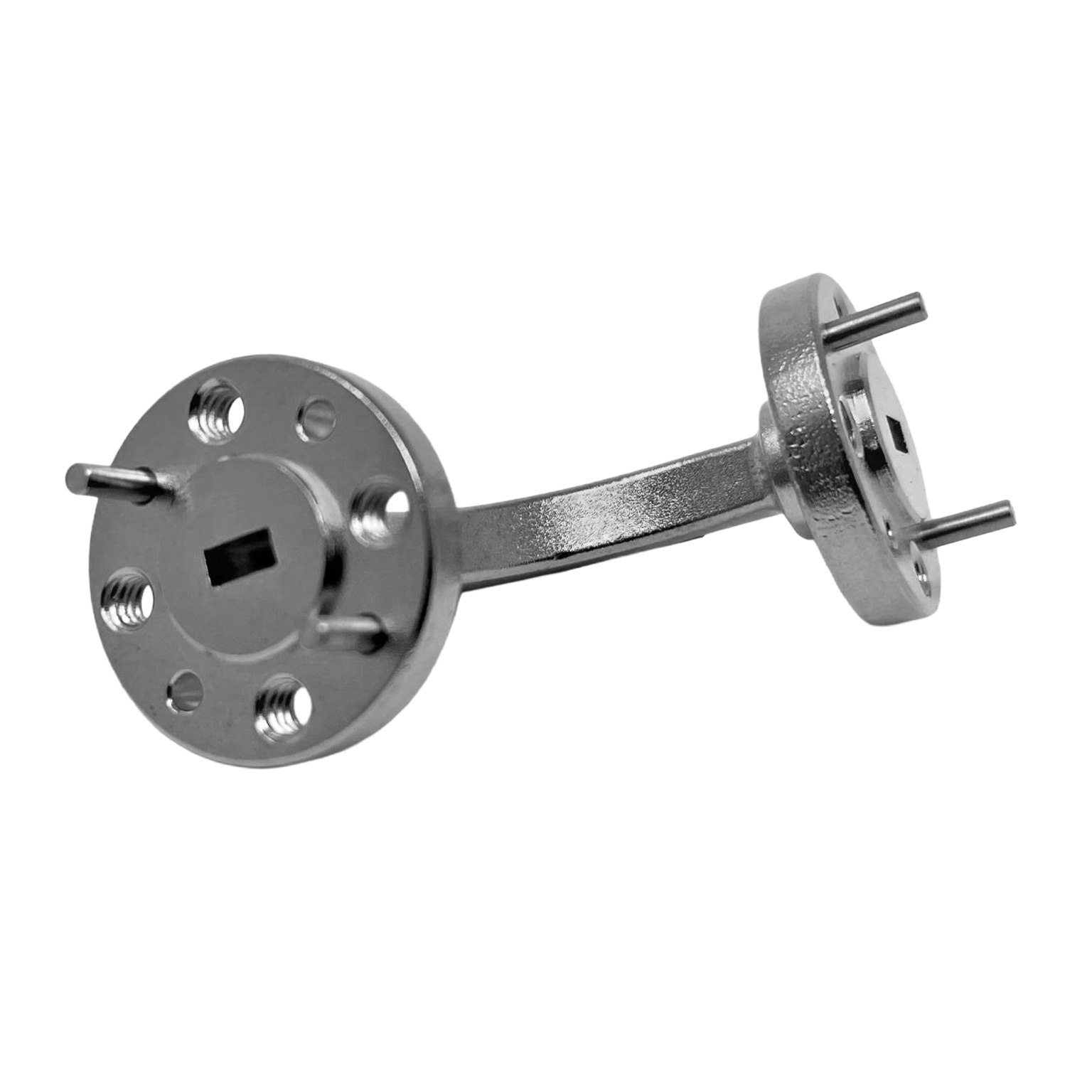
*Actual product may be different from the image shown per customers specifcations
*All data presented is collected from a sample lot.
* Actual data may vary unit to unit, slightly.
*All testing was performed under +25 °C case temperature.
*Consult factory to confirm if material, plating, size, shape, orientation and any electrical parameter is critical for the application as website information is for reference only.
*Millimeter Wave Products, Inc. reserves the right to change the information presented on website without notice as we continue to enhance the performance and design of our products.
Precision H-Plane Waveguide Routing
H-plane bends allow waveguide transmission lines to change direction in the magnetic field plane while maintaining controlled RF behavior and consistent mode propagation.
Standard Bend Angles
Available in 30°, 45°, 60°, and 90° configurations, enabling flexible waveguide routing for a variety of system layouts.
Broad Frequency Coverage
Supporting a wide range of frequencies, these bends are suitable for both microwave and millimeter-wave systems.
Low VSWR Impact
Manufactured to strict tolerances, H-plane bends are designed to minimize reflections and maintain low VSWR impact across the operating band.
Custom Configurations Available
Special angles, bend radii, and mechanical designs can be developed to meet unique system requirements and integration constraints.
Rigid Waveguide Construction
Each bend is constructed as a precision waveguide section to ensure mechanical stability, repeatability, and reliable RF performance.
How H-Plane Bends Work
An H-plane waveguide bend changes the direction of RF propagation by redirecting the signal within the magnetic field plane of the waveguide. As the electromagnetic wave travels through the bend, the waveguide geometry guides the field distribution smoothly through the directional change.
Because the bend alters the physical path of the waveguide, careful control of geometry is essential to maintain the dominant propagation mode and minimize reflections. Parameters such as bend angle, radius, surface finish, and dimensional accuracy all influence performance.
H-plane bends are often preferred in applications where maintaining stable mode behavior and minimizing distortion is critical. When properly designed and manufactured, they allow RF signals to change direction with minimal impact on insertion loss and VSWR.
Applications
Waveguide Transmission Line Routing
H-plane bends provide accurate directional changes in waveguide systems, allowing RF energy to be routed efficiently around mechanical constraints.
RF Test and Development Systems
Commonly used in laboratory and development environments where flexible waveguide routing is required for measurement setups and experimental configurations.
Microwave and Millimeter-Wave Assemblies
Used in high-frequency RF subsystems to enable compact and efficient waveguide layouts without introducing unnecessary loss.
Antenna Feed Systems
Integrated into antenna feed networks where precise waveguide alignment and routing are critical for system performance.
Custom RF System Integration
Custom H-plane bend configurations support specialized RF systems requiring non-standard geometries or compact mechanical designs.
Frequently Asked Questions (FAQ)
What is an H-plane waveguide bend?
An H-plane waveguide bend is a component that changes the direction of RF propagation in the magnetic field plane of a rectangular waveguide.
What bend angles are available?
Standard H-plane bends are available in 30°, 45°, 60°, and 90°, with custom angles available upon request.
What frequency range do these bends support?
Mi-Wave H-plane bends are available from 18 GHz to 320 GHz, depending on waveguide size and configuration.
What is the difference between E-plane and H-plane bends?
E-plane bends change direction in the electric field plane, while H-plane bends change direction in the magnetic field plane. Each affects field distribution and mode behavior differently.
Do waveguide bends affect VSWR?
Yes, bends can introduce reflections if not properly designed. Mi-Wave H-plane bends are precision-manufactured to minimize their impact on system VSWR.
Can custom H-plane bends be made?
Yes. Custom bend angles, radii, and configurations can be developed for specific applications and system requirements.
Where are H-plane bends used?
They are used in waveguide routing, RF test systems, antenna feeds, radar systems, and microwave or millimeter-wave subsystems.
H-Plane Waveguide Bend Calculators
These calculators help estimate insertion loss impact, free-space wavelength, electrical phase shift, bend arc length, and return loss when routing RF signals through H-plane waveguide bends.
Insertion Loss Through Bend
Estimate output power after H-plane waveguide bend insertion loss.
Wavelength Calculator
Calculate free-space wavelength from operating frequency.
Phase Shift Through Bend
Estimate phase shift based on electrical path length through the bend.
Arc Length of Bend
Estimate arc length from bend radius and bend angle.
VSWR to Return Loss
Convert VSWR to return loss to evaluate mismatch through the bend.
Glossary of H-Plane Waveguide Bend Terms
H-Plane Bend
A waveguide bend that redirects RF energy in the magnetic field plane of the waveguide.
H-Plane
The plane associated with the magnetic field orientation in a rectangular waveguide.
Waveguide Bend
A shaped waveguide section used to change the direction of RF transmission.
Bend Angle
The angle through which the waveguide changes direction, such as 30°, 45°, 60°, or 90°.
Bend Radius
The curvature radius of the bend, which influences reflection and mode behavior.
VSWR
Voltage Standing Wave Ratio, a measure of impedance matching and reflected power.
Mode Propagation
The manner in which electromagnetic fields travel through a waveguide.
Mode Conversion
The unwanted transition from one propagation mode to another due to discontinuities.
Rectangular Waveguide
A hollow metallic structure used to guide microwave and millimeter-wave signals.
Millimeter-Wave
Frequencies typically above 30 GHz, where precision waveguide components are critical.
| Model | Band | Frequency (GHz) | Degree | Plane | VSWR (Typ) | RF Ports | Link |
|---|---|---|---|---|---|---|---|
| 67(0/1/2/5)X/39 | X-Band | 8.2-12 | 90°, 30°, 60°, 45° | H-Plane | 1.06:1 | WR-90 Waveguide, UG-39/U Flange | |
| 67(0/1/2/5)K/595 | K-Band | 18-26.5 | 90°, 30°, 60°, 45° | H-Plane | 1.06:1 | WR-42 Waveguide, UG-595/U Flange | |
| 67(0/1/2/5)A/599 | Ka-Band | 26.5-40 | 90°, 30°, 60°, 45° | H-Plane | 1.06:1 | WR-28 Waveguide, UG-599/U Flange | |
| 67(0/1/2/5)B/383 | Q-Band | 33-50 | 90°, 30°, 60°, 45° | H-Plane | 1.06:1 | WR-22 Waveguide, UG-383/U Flange | |
| 67(0/1/2/5)U/383 | U-Band | 40-60 | 90°, 30°, 60°, 45° | H-Plane | 1.12:1 | WR-19 Waveguide, UG-383/U Flange | |
| 67(0/1/2/5)V/385 | V-Band | 50-75 | 90°, 30°, 60°, 45° | H-Plane | 1.15:1 | WR-15 Waveguide, UG-385/U Flange | |
| 67(0/1/2/5)E/387 | E-Band | 60-90 | 90°, 30°, 60°, 45° | H-Plane | 1.15:1 | WR-12 Waveguide, UG-387/U Flange | |
| 67(0/1/2/5)W/387 | W-Band | 75-110 | 90°, 30°, 60°, 45° | H-Plane | 1.15:1 | WR-10 Waveguide, UG-387/U Flange | |
| 67(0/1/2/5)F/387 | F-Band | 90-140 | 90°, 30°, 60°, 45° | H-Plane | 1.15:1 | WR-8 Waveguide, UG-387/U Flange | |
| 67(0/1/2/5)D/387 | D-Band | 110-170 | 90°, 30°, 60°, 45° | H-Plane | 1.15:1 | WR-6 Waveguide, UG-387/U-M Flange | |
| 67(0/1/2/5)G/387 | G-Band | 140-220 | 90°, 30°, 60°, 45° | H-Plane | 1.15:1 | WR-5 Waveguide, UG-387/U Flange | |
| 67(0/1/2/5)H/387 | H-Band | 170-260 | 90°, 30°, 60°, 45° | H-Plane | 1.15:1 | WR-4 Waveguide, UG-387/U Flange | |
| 67(0/1/2/5)J/387 | J-Band | 220-325 | 90°, 30°, 60°, 45° | H-Plane | 1.15:1 | WR-3 Waveguide, UG-387/U Flange |
Return to Bends & Twists Page