

Description:
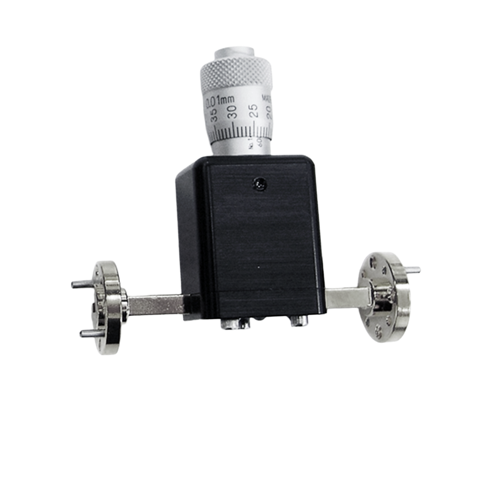
Mi-Wave’s 523 Series Micrometer-driven Calibrated Attenuators are compact precision attenuating devices available in standard waveguide sizes from 18.0 to 220 GHz.Each attenuator is calibrated at the frequency specified at the time of order.
Features
• High Resolution
• Low Cost
• Micrometer Readout
• Differential Screw Drive
• Anti-backlash Operation
• Excellent Mechanical Stability
• Calibration Curve Provided at Specified Frequency
Applications
• Instrumentation
• Manual Test Setups
The standard models shown represent only part of Mi-Wave’s broader product capabilities. Custom configurations are available to support specific frequency bands, interfaces, and application requirements, enabling optimized solutions for specialized RF, microwave, and millimeter-wave systems.
*Actual product may be different from the image shown per customers specifcations
*All data presented is collected from a sample lot.
* Actual data may vary unit to unit, slightly.
*All testing was performed under +25 °C case temperature.
*Consult factory to confirm if material, plating, size, shape, orientation and any electrical parameter is critical for the application as website information is for reference only.
*Millimeter Wave Products, Inc. reserves the right to change the information presented on website without notice as we continue to enhance the performance and design of our products.
Features & Specifications
Mi-Wave’s 523 Series Micrometer-driven Calibrated Attenuators are engineered to provide compact, stable, and precise manual attenuation across microwave and millimeter-wave systems from 18.0 to 220 GHz.
Frequency Coverage: 18.0 GHz to 220 GHz
Available in standard waveguide sizes covering a broad range of microwave and millimeter-wave frequencies for laboratory and instrumentation applications.
Calibrated at Specified Frequency
Each attenuator is calibrated at the frequency specified at the time of order, supporting more precise attenuation reference for the intended operating band or application.
Micrometer Readout
A micrometer-style readout provides fine, controlled manual attenuation adjustment and improved readability for precision setups.
High Resolution Adjustment
Designed for applications that require small, repeatable changes in attenuation for accurate signal level setting.
Differential Screw Drive
The differential screw drive mechanism enables precise motion control for smooth attenuation adjustment with enhanced positioning accuracy.
Anti-Backlash Operation
Engineered to reduce mechanical play during adjustment, helping improve repeatability and maintain accurate settings.
Excellent Mechanical Stability
Provides stable physical performance in laboratory and bench environments, helping maintain consistent attenuation under normal operating conditions.
Compact Design
The small form factor allows easy integration into instrumentation setups and manual RF test benches.
Low-Cost Precision Solution
Offers a practical manual attenuation option for engineers who need high resolution and calibrated performance without more complex automated hardware.
Suitable for Manual Measurement Environments
Well suited for applications where direct user adjustment and dependable calibrated attenuation are preferred.
Applications
Mi-Wave’s 523 Series Micrometer Type Variable Waveguide Attenuators are used in microwave and millimeter-wave systems where fine manual attenuation control and stable calibrated adjustment are required.
Instrumentation
Used in RF, microwave, and millimeter-wave instrumentation setups where precise attenuation control is needed during evaluation and measurement.
Manual Test Setups
Ideal for bench test environments where engineers require direct, hands-on attenuation adjustment without automated interfaces.
Precision Signal Level Setting
Supports accurate manual setting of RF power levels for measurement preparation, component evaluation, and system tuning.
Calibration Support
Useful in applications where a calibrated attenuation reference at a specified frequency is important for repeatable measurement workflows.
Laboratory RF Development
Well suited for engineering development, troubleshooting, and prototype evaluation in microwave and mmWave environments.
Microwave and Millimeter-Wave Measurements
Supports controlled attenuation tasks across standard waveguide bands used in high-frequency laboratory systems.
Educational and Research Environments
Provides a practical precision attenuation tool for universities, research labs, and technical development groups working with waveguide systems.
Frequently Asked Questions (FAQ)
What is a micrometer type variable waveguide attenuator?
A micrometer type variable waveguide attenuator is a manually adjusted attenuator that uses a micrometer-style mechanism to provide fine, controlled RF signal attenuation in a waveguide system.
What frequency range does the 523 Series cover?
The 523 Series is available in standard waveguide sizes covering approximately 18.0 GHz to 220 GHz.
Is the 523 Series calibrated?
Yes. Each attenuator is calibrated at the frequency specified at the time of order.
What is the benefit of a micrometer readout?
A micrometer readout provides finer mechanical control and improved readability, making it easier to set attenuation accurately in manual test environments.
What does anti-backlash operation mean?
Anti-backlash operation reduces unwanted mechanical play in the adjustment mechanism, helping improve repeatability and precision.
What types of applications is the 523 Series used for?
It is commonly used in instrumentation, manual test setups, laboratory RF measurements, and precision signal level setting.
Why would I choose a micrometer-driven attenuator?
A micrometer-driven attenuator is a strong choice when high-resolution manual adjustment, good repeatability, and stable mechanical control are important.
Is the 523 Series suitable for microwave and millimeter-wave testing?
Yes. Its waveguide coverage from 18.0 to 220 GHz makes it suitable for a wide range of microwave and mmWave measurement applications.
RF Attenuator Calculators
These RF attenuator calculators are designed to support microwave and millimeter-wave engineers working with direct reading precision attenuators, waveguide attenuators, and laboratory RF test setups. Use these tools to quickly convert attenuation values, estimate power levels, evaluate cascaded loss, and analyze impedance match performance for systems spanning X-Band through J-Band.
dB to Power Ratio
Convert attenuation or gain in decibels to a linear power ratio.
Power Ratio to dB
Convert a linear power ratio into decibels.
dBm to Watts
Convert RF power in dBm to watts for test and system-level calculations.
Watts to dBm
Convert watts to dBm for RF signal level analysis.
Cascaded Attenuation Calculator
Add multiple attenuator values together to determine total path attenuation.
VSWR to Return Loss
Estimate return loss from a known VSWR value.
Glossary of Micrometer Type Variable Waveguide Attenuator Terms
Attenuator Fundamentals
Variable Attenuator
An attenuator that allows the user to adjust the amount of RF signal reduction over a defined range.
Calibrated Attenuator
An attenuator with known attenuation reference, used when more repeatable or defined signal level setting is required.
Waveguide Attenuator
An attenuator designed for use in rectangular waveguide systems at microwave and millimeter-wave frequencies.
Micrometer Type Attenuator
An attenuator that uses a micrometer-style adjustment mechanism for fine manual control.
Electrical Performance
Attenuation (dB)
The reduction of RF signal power expressed in decibels.
High Resolution
The ability to make very small changes in attenuation for precise signal control.
Calibration Frequency
The specific frequency at which the attenuator is calibrated to provide its reference attenuation performance.
Insertion Loss
The signal loss introduced by a component in addition to its intended attenuation behavior.
VSWR (Voltage Standing Wave Ratio)
A measure of impedance matching between RF components and transmission paths.
RF and Frequency
Radio Frequency (RF)
Electromagnetic signals used for communications, sensing, and measurement.
Microwave Frequencies
Frequencies generally spanning 1 GHz to 30 GHz.
Millimeter-Wave (mmWave)
Frequencies from 30 GHz to 300 GHz used in advanced communications, radar, and high-frequency testing.
Frequency Range
The operating span of frequencies supported by the attenuator.
Waveguide Size
The physical dimensions of a waveguide interface, which determine its usable frequency range.
Mechanical and Design
Micrometer Readout
A fine mechanical readout used to indicate small adjustment increments for precise manual setting.
Differential Screw Drive
A precision mechanical drive mechanism that provides fine motion control by combining screw threads of different pitch.
Anti-Backlash Operation
A design approach that reduces looseness or play in a mechanical adjustment system to improve repeatability.
Mechanical Stability
The ability of a device to maintain its physical setting and performance under normal handling and operating conditions.
Compact Design
A small physical form factor that allows easier integration into measurement systems and laboratory setups.
Measurement and Applications
Instrumentation
RF and microwave equipment used to measure, monitor, and evaluate signal behavior and component performance.
Manual Test Setup
A non-automated test environment where settings are adjusted directly by the user.
Signal Level Setting
The process of adjusting attenuation or gain to establish the desired RF power level in a system or test chain.
Laboratory Measurement
RF testing and evaluation performed in controlled lab environments using instruments and reference components.
Calibration Curve
A reference plot or dataset showing attenuation performance at a specified frequency, supplied to support measurement accuracy.
Note: Our website contains just a few types of Attenuators we build. Consult with us for your specific needs.
| Model | Minimum Frequency (GHz) | Maximum Frequency (GHz) | Attenuation Range (dB) | Average Power Handling (Watts) | Insertion Loss at 0 dB setting | RF Ports | LINK |
|---|---|---|---|---|---|---|---|
| 523K/595 | 18 | 26.5 | 0-30 | 0.3 | 0.3 | WR-42 Waveguide UG-595/U Flange | |
| 523A/599 | 26.5 | 40 | 0-30 | 0.3 | 0.3 | WR-28 Waveguide UG-599/U Flange | |
| 523B/383 | 33 | 50 | 0-30 | 0.3 | 0.4 | WR-22 Waveguide UG-383/U Flange | |
| 523U/383 | 40 | 60 | 0-25 | 0.2 | 0.3 | WR-19 Waveguide UG-383/U-M Flange | |
| 523V/385 | 50 | 75 | 0-25 | 0.2 | 0.4 | WR-15 Waveguide UG-385/U Flange | |
| 523E/387 | 60 | 90 | 0-25 | 0.2 | 0.3 | WR-12 Waveguide UG-387/U-M Flange | |
| 523W/387 | 75 | 110 | 0-25 | 0.1 | 0.4 | WR-10 Waveguide UG-387/U-M Flange | |
| 523F/387 | 90 | 140 | 0-30 | 0.1 | 0.5 | WR-08 Waveguide UG-387/U-M Flange | |
| 523D/387 | 110 | 170 | 0-25 | 0.1 | 0.5 | WR-06 Waveguide UG-387/U-M Flange | |
| 523G/387 | 140 | 220 | 0-25 | 0.1 | 0.8 | WR-05 Waveguide UG-387/U-M Flange |
Variable Waveguide Attenuators – Micrometer Driven
The 523 Series Micrometer-driven Calibrated Attenuators are designed for laboratory applications in standard waveguide bands from 18.0 to 220.0 GHz. The drive mechanism is designed for the high resolution of vane insertion vs. attenuation characteristics that is required for the small waveguide dimensions associated with the higher millimeter wave frequencies. These attenuators are very useful for insertion loss measurements, and a wide variety of other attenuation and power level determinations