
Products> Antenna Products > Spot Focus Antennas
Product Description
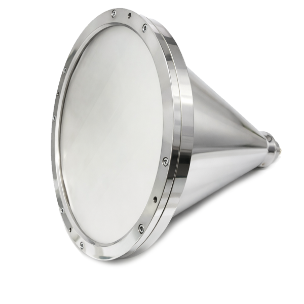
Mi-Wave’s Spot Focus Antennas, including the 257 Series, are high-performance directional antennas designed to deliver tight beamwidth, high gain, and stable radiation patterns across RF, microwave, and millimeter-wave frequency bands.
These antennas are engineered for applications that require precise energy focusing, strong directional performance, and excellent sidelobe control. By combining optimized reflector geometries with precision feed designs, spot focus antennas concentrate RF energy into a highly focused beam, improving link margin, spatial resolution, and interference rejection in demanding system environments.
Spot focus antennas are well suited for communications systems, radar platforms, antenna measurement ranges, and RF test environments where accurate beam control and repeatable performance are essential. Their focused radiation characteristics make them particularly valuable in applications requiring long-range performance, narrow illumination zones, and controlled signal coverage.
Available with standard waveguide interfaces, Mi-Wave’s 257 Series Spot Focus Antennas support a wide range of frequency bands commonly used in microwave and millimeter-wave systems. These antennas provide a reliable solution for engineers seeking high-gain performance, predictable beam characteristics, and flexible integration into advanced RF system designs.
The standard 257 Series models represent only part of Mi-Wave’s broader antenna capabilities. Custom spot focus antenna designs are available to support specific frequency bands, waveguide interfaces, gain targets, polarization requirements, reflector sizes, and application-specific system needs.
Note: Our website contains just a few types of Antennas we build. Consult with us for your specific needs.
| Waveguide Band | Model No. | Reflector diameter (inches) | Circular Waveguide Internal Diameter (.XXX in Model No.) in Inches | Frequency Range (GHz) | Spot Size (inches) | Focal Length (inches) | Polarization | VSWR | Antenna Port | Lens material | Housing material |
|---|---|---|---|---|---|---|---|---|---|---|---|
| X Band | 257X-12/.XXX/39 | 12 | .XXX=1.094 .XXX=.938 .XXX= .797 | 8.2-9.97 8.5-11.6 9.97-12.4 | 1.0-1.5 | 12- 14 | Circular Polarized | 1.3:1 | Circular Waveguide with UG-39/U Flange | Rexolite | HDPE |
| Ku Band | 257Ku-9/.XXX/419 | 9 | XXX=.660 XXX=.550 | 12.4-14.6 14.6-18 | 1.0-1.5 | 9- 10 | Circular Polarized | 1.3:1 | Circular Waveguide with UG-419/U Flange | Rexolite | HDPE |
| Ku Band | 257Ku-12/.XXX/419 | 12 | XXX=.660 XXX=.550 | 12.4-14.6 14.6-18 | 1.0-1.5 | 12- 14 | Circular Polarized | 1.3:1 | Circular Waveguide with UG-419/U Flange | Rexolite | HDPE |
| K Band | 257K-6/.XXX/595 | 6 | XXX=.470 XXX .396 XXX=.328 | 18-20.5 20.4-24.5 24.5-26.5 | 1.0-1.5 | 8 | Circular Polarized | 1.3:1 | Circular Waveguide with UG-595/U Flange or UG-425/U Flange | Rexolite | HDPE |
| K Band | 257K-9/.XXX/595 | 9 | XXX=.470 XXX .396 XXX=.328 | 18-20.5 20.4-24.5 24.5-26.5 | 1.0-1.5 | 9- 10 | Circular Polarized | 1.3:1 | Circular Waveguide with UG-595/U Flange or UG-425/U Flange | Rexolite | HDPE |
| K Band | 257K-12/.XXX/595 | 12 | XXX=.470 XXX .396 XXX=.328 | 18-20.5 20.4-24.5 24.5-26.5 | 1.0-1.5 | 12- 14 | Circular Polarized | 1.3:1 | Circular Waveguide with UG-595/U Flange or UG-425/U Flange | Rexolite | HDPE |
| Ka-Band | 257A-6/.XXX/599 | 6 | XXX=.328 XXX=.281 XXX=.250 XXX= .219 | 26.5-28.5 28.5-33.0 33.0 -38.5 38.5-40.0 | 1.0-1.5 | 8 | Circular Polarized | 1.3:1 | Circular Waveguide with UG-599/U Flange or UG-381/U Flange | Rexolite | HDPE |
| Ka-Band | 257A-9/.XXX/599 | 9 | XXX=.328 XXX=.281 XXX=.250 XXX= .219 | 26.5-28.5 28.5-33.0 33.0 -38.5 38.5-40.0 | 1.0-1.5 | 9- 10 | Circular Polarized | 1.3:1 | Circular Waveguide with UG-599/U Flange or UG-381/U Flange | Rexolite | HDPE |
| Ka-Band | 257A-12/.XXX/599 | 12 | XXX=.328 XXX=.281 XXX=.250 XXX= .219 | 26.5-28.5 28.5-33.0 33.0 -38.5 38.5-40.0 | 1.0-1.5 | 12- 14 | Circular Polarized | 1.3:1 | Circular Waveguide with UG-599/U Flange or UG-381/U Flange | Rexolite | HDPE |
| Q-Band | 257B-3/.XXX/383 | 3 | XXX=.250 XXX=.219 XXX=.188 | 33.0-38.5 38.5-43.0 43.0-50.0 | 1.0-1.5 | 4 | Circular Polarized | 1.3:1 | Circular Waveguide with UG-383/U Flange | Rexolite | Aluminum |
| Q-Band | 257B-6/.XXX/383 | 6 | XXX=.250 XXX=.219 XXX=.188 | 33.0-38.5 38.5-43.0 43.0-50.0 | 1.0-1.5 | 8 | Circular Polarized | 1.3:1 | Circular Waveguide with UG-383/U Flange | Rexolite | HDPE |
| Q-Band | 257B-9/.XXX/383 | 9 | XXX=.250 XXX=.219 XXX=.188 | 33.0-38.5 38.5-43.0 43.0-50.0 | 1.0-1.5 | 9- 10 | Circular Polarized | 1.3:1 | Circular Waveguide with UG-383/U Flange | Rexolite | HDPE |
| Q-Band | 257B-12/.XXX/383 | 12 | XXX=.250 XXX=.219 XXX=.188 | 33.0-38.5 38.5-43.0 43.0-50.0 | 1.0-1.5 | 12- 14 | Circular Polarized | 1.3:1 | Circular Waveguide with UG-383/U Flange | Rexolite | HDPE |
| U-band | 257U-3/.XXX/383 | 3 | XXX=.219 XXX=.188 XXX=.165 XXX=.141 | 38.5-43.0 43.0-50.0 50.0-58.0 58.0-60.0 | 1.0-1.5 | 4 | Circular Polarized | 1.3:1 | Circular Waveguide with UG-383/U-M Flange | Rexolite | Aluminum |
| U-band | 257U-6/.XXX/383 | 6 | XXX=.219 XXX=.188 XXX=.165 XXX=.141 | 38.5-43.0 43.0-50.0 50.0-58.0 58.0-60.0 | 1.0-1.5 | 8 | Circular Polarized | 1.3:1 | Circular Waveguide with UG-383/U-M Flange | Rexolite | HDPE |
| U-band | 257U-9/.XXX/383 | 9 | XXX=.219 XXX=.188 XXX=.165 XXX=.141 | 38.5-43.0 43.0-50.0 50.0-58.0 58.0-60.0 | 1.0-1.5 | 9- 10 | Circular Polarized | 1.3:1 | Circular Waveguide with UG-383/U-M Flange | Rexolite | HDPE |
| U-band | 257U-12/.XXX/383 | 12 | XXX=.219 XXX=.188 XXX=.165 XXX=.141 | 38.5-43.0 43.0-50.0 50.0-58.0 58.0-60.0 | 1.0-1.5 | 12- 14 | Circular Polarized | 1.3:1 | Circular Waveguide with UG-383/U-M Flange | Rexolite | HDPE |
| V-band | 257V-3/.XXX/385 | 3 | XXX=.165 XXX=.141 XXX=.125 | 50.0-58.0 58.0-68.0 68.0-75.0 | 1.0-1.5 | 4 | Circular Polarized | 1.3:1 | Circular Waveguide with UG-385/U Flange | Rexolite | Aluminum |
| V-band | 257V-6/.XXX/385 | 6 | XXX=.165 XXX=.141 XXX=.125 | 50.0-58.0 58.0-68.0 68.0-75.0 | 1.0-1.5 | 8 | Circular Polarized | 1.3:1 | Circular Waveguide with UG-385/U Flange | Rexolite | HDPE |
| V-band | 257V-9/.XXX/385 | 9 | XXX=.165 XXX=.141 XXX=.125 | 50.0-58.0 58.0-68.0 68.0-75.0 | 1.0-1.5 | 9- 10 | Circular Polarized | 1.3:1 | Circular Waveguide with UG-385/U Flange | Rexolite | HDPE |
| V-band | 257V-12/.XXX/385 | 12 | XXX=.165 XXX=.141 XXX=.125 | 50.0-58.0 58.0-68.0 68.0-75.0 | 1.0-1.5 | 12- 14 | Circular Polarized | 1.3:1 | Circular Waveguide with UG-385/U Flange | Rexolite | HDPE |
| E-band | 257E-3/.XXX/387 | 3 | XXX=.141 XXX=.125 XXX=.110 XXX=.094 | 60.0-68.0 68.0-77.0 77.0-87.0 87.0-90.0 | 1.0-1.5 | 4 | Circular Polarized | 1.3:1 | Circular Waveguide with UG-387/U Flange | Rexolite | Aluminum |
| E-band | 257E-6/.XXX/387 | 6 | XXX=.141 XXX=.125 XXX=.110 XXX=.094 | 60.0-68.0 68.0-77.0 77.0-87.0 87.0-90.0 | 1.0-1.5 | 8 | Circular Polarized | 1.3:1 | Circular Waveguide with UG-387/U Flange | Rexolite | HDPE |
| E-band | 257E-9/.XXX/387 | 9 | XXX=.141 XXX=.125 XXX=.110 XXX=.094 | 60.0-68.0 68.0-77.0 77.0-87.0 87.0-90.0 | 1.0-1.5 | 9- 10 | Circular Polarized | 1.3:1 | Circular Waveguide with UG-387/U Flange | Rexolite | HDPE |
| E-band | 257E-12/.XXX/387 | 12 | XXX=.141 XXX=.125 XXX=.110 XXX=.094 | 60.0-68.0 68.0-77.0 77.0-87.0 87.0-90.0 | 1.0-1.5 | 12- 14 | Circular Polarized | 1.3:1 | Circular Waveguide with UG-387/U Flange | Rexolite | HDPE |
| W-band | 257W-3/.XXX/387 | 3 | XXX=.125 XXX=.110 XXX=.094 XXX=.082 | 75.0-77.0 77.0-87.0 87.0-100.0 100.0-110.0 | 1.0-1.5 | 4 | Circular Polarized | 1.3:1 | Circular Waveguide with UG-387/U-M Flange | Rexolite | Aluminum |
| W-band | 257W-6/.XXX/387 | 6 | XXX=.125 XXX=.110 XXX=.094 XXX=.082 | 75.0-77.0 77.0-87.0 87.0-100.0 100.0-110.0 | 1.0-1.5 | 8 | Circular Polarized | 1.3:1 | Circular Waveguide with UG-387/U-M Flange | Rexolite | HDPE |
| W-band | 257W-9/.XXX/387 | 9 | XXX=.125 XXX=.110 XXX=.094 XXX=.082 | 75.0-77.0 77.0-87.0 87.0-100.0 100.0-110.0 | 1.0-1.5 | 9- 10 | Circular Polarized | 1.3:1 | Circular Waveguide with UG-387/U-M Flange | Rexolite | HDPE |
| W-band | 257W-12/.XXX/387 | 12 | XXX=.125 XXX=.110 XXX=.094 XXX=.082 | 75.0-77.0 77.0-87.0 87.0-100.0 100.0-110.0 | 1.0-1.5 | 12- 14 | Circular Polarized | 1.3:1 | Circular Waveguide with UG-387/U-M Flange | Rexolite | HDPE |
*All data presented is collected from a sample lot.
* Actual data may vary unit to unit, slightly.
*All testing was performed under +25 °C case temperature.
*Consult factory to confirm if material, plating, size, shape, orientation and any electrical parameter is critical for the application as website information is for reference only.
*Millimeter Wave Products, Inc. reserves the right to change the information presented on website without notice as we continue to enhance the performance and design of our products.
Spot Focus Antenna Engineering Calculators
These RF engineering calculators help estimate antenna performance for spot focus antennas, including communications systems, radar platforms, antenna measurement ranges, and microwave and millimeter-wave test environments. Use them to calculate antenna gain, beamwidth, reflector diameter required for target gain, effective aperture, free-space path loss, and wavelength across RF, microwave, and millimeter-wave frequencies.
Spot focus antennas are designed for tight beamwidth, focused energy distribution, and strong directional performance. A typical starting efficiency range for many systems is 0.50 to 0.70.
Antenna Gain Calculator
Antenna Gain (dBi):
Antenna Beamwidth Calculator
Reflector Size Required for Target Gain
Antenna Effective Aperture Calculator
Effective Aperture (m²):
Free Space Path Loss Calculator
RF Wavelength Calculator
Wavelength (mm):
Key Features & Performance Benefits
Tight Beamwidth Performance
Spot focus antennas are designed to produce narrow, highly focused beams for applications requiring precise directional control. Their concentrated radiation pattern supports long-range operation, improved spatial resolution, and reduced signal spread.
High Gain Directional Performance
These antennas provide strong directional gain across RF, microwave, and millimeter-wave frequencies, making them well suited for communications, radar, and measurement systems that require efficient energy focusing.
Excellent Sidelobe Control
Optimized reflector geometry and precision feed design help reduce sidelobe levels and minimize unwanted radiation outside the main beam. This improves interference rejection and supports cleaner overall system performance.
Focused Energy Distribution
Spot focus antennas concentrate RF energy into a defined coverage area, making them ideal for applications where controlled illumination, narrow coverage zones, or high target resolution are required.
Stable Radiation Patterns
These antennas deliver repeatable and predictable beam characteristics across their operating range, supporting consistent performance in both operational deployments and controlled RF test environments.
Optimized for Long-Range Applications
The combination of high gain and tight beamwidth makes spot focus antennas especially effective in long-distance links, remote sensing, and precision target illumination systems.
Wide Range of Beamwidth and Reflector Options
Available in multiple reflector sizes and beamwidth configurations, spot focus antennas can be selected to match specific system requirements for coverage, gain, and spatial resolution.
Supports Microwave and Millimeter-Wave Systems
Spot focus antennas are used across a broad range of RF bands commonly found in microwave and millimeter-wave applications, supporting advanced communications, radar, and research systems.
Standard Waveguide Interface Compatibility
Available with standard waveguide interfaces, these antennas can be integrated into existing RF and microwave systems with greater ease, supporting flexible installation and system design.
Custom Configurations Available
Mi-Wave offers custom spot focus antenna solutions for specific frequency bands, waveguide sizes, gain targets, polarization schemes, reflector geometries, and application-specific integration needs.
Applications
Mi-Wave Spot Focus Antennas are widely used in RF, microwave, and millimeter-wave systems that require tight beamwidth, high gain, and precise energy focusing. Their ability to concentrate RF energy into a defined coverage area makes them ideal for applications where directional accuracy, long-range performance, and interference control are critical.
These antennas support applications in satellite communications, radar systems, antenna measurement ranges, wireless research, and EMC testing, where controlled beam shaping and repeatable performance are essential.
Satellite Communications (SatCom)
Spot focus antennas are used in satellite communication systems where narrow beamwidth and high gain are required to maintain strong, reliable links over long distances.
Typical satcom applications include:
- Satellite ground terminals and gateway systems
- High-frequency microwave and millimeter-wave links
- Experimental and research-based satellite communication systems
- Telemetry and tracking systems
- RF link testing and validation
Their focused radiation pattern improves link efficiency, signal quality, and interference rejection in dense RF environments.
Radar Systems and Testing
Spot focus antennas are well suited for radar applications that require precise target illumination and high spatial resolution.
Common radar applications include:
- Radar cross-section (RCS) testing
- Target detection and tracking systems
- FMCW and pulse radar platforms
- Precision radar measurement systems
- Millimeter-wave radar research
Their narrow beam enables accurate signal targeting and improved measurement precision.
Antenna Measurement Ranges
Spot focus antennas are used in antenna measurement environments where controlled illumination and accurate beam shaping are required.
Typical measurement applications include:
- Antenna gain and radiation pattern measurements
- Near-field and far-field testing
- Calibration of RF antennas and systems
- Beamwidth and sidelobe verification
- Antenna characterization and validation
Their stable and focused beam supports high-accuracy RF measurements and repeatable test conditions.
RF and Microwave Laboratory Research
Research laboratories and engineering teams use spot focus antennas for experimental RF systems and high-frequency development.
Typical research applications include:
- Wireless propagation studies
- Microwave and millimeter-wave system development
- RF component and subsystem testing
- Advanced antenna research
- Academic and government research programs
These antennas provide a reliable platform for controlled RF experimentation and system prototyping.
EMC and RF Testing
Spot focus antennas are used in electromagnetic compatibility (EMC) environments where directional control and focused signal delivery are required.
Common EMC applications include:
- Radiated emissions testing
- RF susceptibility testing
- Controlled RF illumination in test chambers
- EMC compliance verification
- System-level RF validation
Their directional performance allows engineers to focus RF energy precisely, improving test accuracy and repeatability.
Frequently Asked Questions (FAQ)
What is a spot focus antenna?
A spot focus antenna is a directional reflector antenna designed to concentrate RF energy into a tightly focused beam. This results in high gain, narrow beamwidth, and precise directional control, making it ideal for long-range and high-resolution applications.
What are the advantages of spot focus antennas?
Spot focus antennas offer tight beamwidth, high gain, excellent sidelobe control, and precise energy focusing. These characteristics improve signal strength, spatial resolution, and interference rejection in demanding RF environments.
What frequencies do spot focus antennas support?
Spot focus antennas operate across RF, microwave, and millimeter-wave frequency bands, typically ranging from a few GHz up to 110 GHz, depending on the antenna design and configuration.
How is a spot focus antenna different from a standard reflector antenna?
Unlike standard reflector antennas, spot focus antennas are specifically designed to concentrate energy into a smaller, more defined beam, improving directional accuracy and reducing signal spread.
What determines gain in a spot focus antenna?
Antenna gain is determined by reflector size, operating frequency, and efficiency. Larger apertures and higher frequencies generally produce higher gain and tighter beamwidth.
What is beamwidth in a spot focus antenna?
Beamwidth refers to the angular width of the main radiation beam. Spot focus antennas are engineered for narrow beamwidth, enabling precise targeting and improved signal concentration.
What are spot focus antennas used for?
Spot focus antennas are used in:
- Satellite communications (SatCom)
- Radar systems and testing
- Antenna measurement ranges
- RF and microwave laboratories
- EMC and RF testing
- Millimeter-wave research
Are spot focus antennas suitable for long-range applications?
Yes. Their high gain and focused beam characteristics make them well suited for long-distance communication, remote sensing, and precision targeting systems.
Are spot focus antennas suitable for measurement applications?
Yes. Their stable radiation patterns and controlled beam shape make them ideal for antenna calibration, gain measurements, and precision RF testing.
Can spot focus antennas be customized?
Yes. Spot focus antennas can be customized for frequency range, reflector size, beamwidth, gain, polarization, waveguide interface, and mechanical configuration to meet specific system requirements.
What interfaces are available for spot focus antennas?
Spot focus antennas are typically available with standard waveguide interfaces, allowing for straightforward integration into RF, microwave, and millimeter-wave systems.
How do spot focus antennas improve system performance?
By concentrating RF energy into a focused beam, these antennas improve link margin, signal clarity, interference rejection, and overall system efficiency, especially in high-frequency and high-precision applications.
Glossary of Spot Focus Antenna Terms
This glossary defines key terminology related to spot focus antennas used in RF, microwave, and millimeter-wave systems where tight beamwidth, high gain, and precise energy focusing are required. These antennas are commonly used in satellite communications, radar systems, antenna measurement ranges, RF laboratories, EMC testing, and advanced research applications.
Antenna Fundamentals
Spot Focus Antenna
A directional reflector antenna designed to concentrate RF energy into a tightly focused beam for improved gain, spatial resolution, and directional control.
Reflector Antenna
An antenna that uses a reflective surface to direct electromagnetic energy into a focused beam.
Feed System
The component that launches RF energy toward the reflector, influencing beam shape, efficiency, and overall antenna performance.
Aperture
The physical opening through which RF energy is radiated or received.
Aperture Area
The surface area of the antenna aperture, which directly impacts gain and beamwidth.
Radiation Characteristics
Antenna Gain
A measure of how effectively an antenna directs RF energy in a specific direction.
Directivity
The ability of an antenna to focus energy in a preferred direction.
Beamwidth
The angular width of the main radiation beam.
Half-Power Beamwidth (HPBW)
The angle between points where the signal level drops by 3 dB from the peak.
Focused Beam
A concentrated radiation pattern that directs energy into a narrow region for improved signal strength and precision.
Sidelobes
Secondary radiation patterns outside the main beam that can cause interference or reduce measurement accuracy.
Radiation Pattern
A graphical representation of how RF energy is distributed in space.
Performance and Efficiency
Aperture Efficiency
The effectiveness of the antenna in converting its physical aperture into usable radiated energy.
Effective Aperture (Ae)
The area over which the antenna effectively transmits or receives RF energy.
Spillover Loss
RF energy that does not properly reflect or focus within the antenna structure, reducing efficiency.
Phase Error
Non-uniform phase distribution across the aperture that can degrade beam quality and reduce gain.
Gain-to-Beamwidth Relationship
A fundamental tradeoff where higher gain typically results in narrower beamwidth.
RF and Frequency Terms
Radio Frequency (RF)
Electromagnetic frequencies used for communication, radar, and sensing applications.
Microwave Frequencies
Typically defined as 1 GHz to 30 GHz.
Millimeter-Wave (mmWave)
Typically defined as 30 GHz to 300 GHz.
Wavelength (λ)
The distance between repeating points of an electromagnetic wave.
Frequency (f)
The number of cycles per second, typically expressed in GHz for RF systems.
Applications and Systems
Satellite Communications (SatCom)
Systems that use satellites to transmit and receive RF signals over long distances.
Radar Systems
Systems that use RF signals to detect, track, and analyze objects.
Antenna Measurement Range
A controlled test environment used to evaluate antenna performance such as gain, beamwidth, and radiation patterns.
EMC Testing
Testing to ensure electronic systems operate without causing or experiencing electromagnetic interference.
RF Test Systems
Equipment used to measure, analyze, and validate RF system performance.
Frequency Bands
- L-Band: 1–2 GHz
- S-Band: 2–4 GHz
- C-Band: 4–8 GHz
- X-Band: 8–12 GHz
- Ku-Band: 12–18 GHz
- Ka-Band: 26–40 GHz
- Q-Band: 33–50 GHz
- V-Band: 50–75 GHz
- W-Band: 75–110 GHz
These bands are commonly used in satellite communications, radar systems, wireless links, and millimeter-wave research applications.
Why Choose Mi-Wave
Mi-Wave is a trusted manufacturer of microwave and millimeter-wave antennas and RF components, with decades of experience supporting advanced communication, radar, and test systems. Our 257 Series Spot Focus Antennas are engineered for repeatable performance, mechanical precision, and long-term reliability in demanding applications.
Mi-Wave’s sales engineering team works directly with customers to recommend the appropriate waveguide size, frequency band, and antenna configuration, including custom designs when standard models do not meet system requirements.