
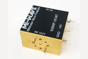
Generating a stable, low-noise signal at 94 GHz directly from an oscillator is one of the hardest problems in millimeter wave hardware design. The physics that enable low phase noise at microwave frequencies become increasingly uncooperative above 50 GHz, and the oscillator architectures that work well at 10 GHz do not translate to W-band without severe performance degradation. This is why frequency multiplication – and in particular the mmWave frequency doubler – has become a foundational technique in radar and electronic warfare front-end design.
Rather than generating the required millimeter wave frequency directly, engineers synthesise it by multiplying a lower-frequency, lower – noise reference signal by an integer factor. A frequency doubler takes an input at frequency f and produces a dominant output at 2f, using the nonlinear transfer characteristics of high-frequency junction devices to generate harmonics and then filtering to retain only the desired output harmonic.
This article examines how a frequency doubler works at the circuit level, what performance parameters define its suitability for radar and EW applications, and why the choice of multiplication architecture has direct consequences for the phase noise, spurious performance, and system noise figure of the complete signal chain.
Why Multiply Rather Than Oscillate Directly
The primary motivation for frequency multiplication in millimeter wave systems is phase noise performance. A voltage-controlled oscillator operating at frequency f0 has a phase noise spectral density that scales with frequency: when the output frequency is doubled, the phase noise floor increases by , where N is multiplication factor, corresponding to 6 dB. This means that multiplying a high-quality 24 GHz oscillator by four to reach 96 GHz adds 12 dB to the phase noise – but that penalty is almost always better than the phase noise achievable from a direct 96 GHz oscillator, because the absolute noise performance of oscillators degrades rapidly as operating frequency increases.
Beyond phase noise, lower-frequency synthesisers benefit from well-developed phase-locked loop technology with reference injection locking, sub-femtosecond jitter, and decades of characterised circuit topologies. By keeping the frequency synthesis below 30 GHz and multiplying up to the required millimeter wave frequency, radar and EW designers inherit all of that maturity while reaching operating frequencies that no stable direct synthesiser can yet achieve with comparable spectral purity.
Circuit-Level Operation: Nonlinearity and Harmonic Generation
Passive Frequency Doublers
The most widely used mmWave frequency doubler architecture at frequencies above 50 GHz is built around nonlinear junction devices whose current-voltage characteristics are strongly exponential. When a sinusoidal signal at frequency f drives such a device, the output current contains components at f, 2f, 3f, and higher harmonics. A bandpass filter centred at 2f then passes the desired second harmonic and suppresses the fundamental and higher-order products.
In a balanced anti-parallel configuration, the circuit’s odd symmetry suppresses all odd harmonics – including the fundamental – at the output port, because their contributions from the two devices cancel. The even harmonics add constructively. This is advantageous for doubler applications: fundamental rejection better than 20 dB can be achieved from the circuit topology alone before any additional filtering, reducing the filter design burden considerably.
Passive frequency doublers are widely used from Ka-band through W-band and into sub-THz frequencies. Their inherent conversion loss – the ratio of output power at 2f to input power at f – typically ranges from 6 dB to 12 dB depending on frequency and embedding impedance design. This loss must be compensated by driver amplification either before the doubler stage, and the noise contribution of that amplification must be carefully managed in receive-path applications.
Active Frequency Doubler Designs
At frequencies where conversion loss budget is tight, active frequency doubler designs using high-frequency amplifier devices biased in a nonlinear operating region offer an alternative. A high – frequency transistor biased near its threshold operates in a strongly nonlinear region where its output current waveform is rich in even harmonics. With appropriate output matching at 2f and input matching at f, these designs produce useful conversion gain rather than the inherent conversion loss of passive doublers.
High-frequency active doublers operating at input frequencies above 100 GHz have been demonstrated using advanced compound semiconductor processes, producing outputs in the 200–500 GHz range – frequencies relevant to emerging sub-THz radar, imaging, and scientific research applications. As component technology at these frequencies continues to mature, active doubler designs are increasingly available as precision sub-THz components from specialist millimeter wave manufacturers.
Conversion Loss and Drive Level Sensitivity
For passive frequency doublers, conversion loss is a critical figure of merit. The conversion loss is frequency-dependent and sensitive to input drive level. At too low a drive level, the device operates in its linear region and harmonic generation is inefficient. At too high a drive level, the device enters deep saturation, the output current waveform clips, and higher-order spurious products increase significantly.
The optimal input drive level – typically specified as the input power for minimum conversion loss – is a primary characterisation parameter for any frequency doubler. In radar and EW systems, maintaining this drive level consistently across operating temperature and across the full tuning bandwidth is a key design challenge for the driver amplifier stage that precedes the doubler.
Performance Parameters for Radar and EW Applications
The requirements placed on a mmWave frequency doubler differ substantially between radar and electronic warfare applications, and understanding those differences is essential for correct component selection.
Radar Local Oscillator Chains
In a radar receiver, the local oscillator signal derived from the frequency doubler drives the mixer that down-converts the received radar return. Phase noise on the LO directly limits the radar’s Doppler velocity resolution and its ability to detect slow-moving targets against clutter. For a pulsed Doppler radar, the required LO phase noise at offsets from 1 kHz to 1 MHz from the carrier is typically specified at better than -90 dBc/Hz at 10 kHz offset, with many imaging radar systems requiring -100 dBc/Hz or below.
Frequency doublers in radar LO chains must therefore preserve the phase noise performance of the upstream synthesiser. The close-in phase noise added by the doubler stage itself – from flicker noise upconversion in the active or passive device – can become the limiting factor when very high-quality synthesisers are used, making device selection and bias optimisation as important as the conversion loss specification.
Electronic Warfare Frequency Synthesis
In electronic warfare systems – both jamming transmitters and receiver-based ESM equipment – the mmWave frequency doubler is used differently. EW transmitters require rapid frequency agility across wide bandwidths, often covering multi-octave ranges within microseconds to implement frequency-hopping or noise jamming waveforms. The doubler in an EW LO chain must maintain its conversion loss and spurious performance across the full tuning range, not just at a single spot frequency.
Key parameters for EW applications include:
- Fundamental suppression across tuning range: Any leakage of the input fundamental through to the output port can interfere with the EW system’s own receiver or create an unintended RF emission that reveals the platform’s frequency plan to adversarial ESM systems.
- Second harmonic flatness: Variation in conversion loss as a function of input frequency translates to variation in transmitter EIRP across the jamming band, creating spectral holes in the coverage.
- Spurious output levels: Products at 3f, 4f, and intermodulation products from any residual fundamental must meet spurious emission specifications, which in EW systems are often defined by platform electromagnetic compatibility constraints rather than signal quality alone.
- Settling time: In agile systems, the time required for any associated tuning or matching network to settle as the input frequency changes determines the minimum dwell time and ultimately the agility of the EW transmitter.
Integration Into the Signal Chain
Driver Amplifier Requirements
Because passive frequency doublers have inherent conversion loss, the amplifier stage driving the doubler input must deliver a consistent power level across the tuning band. Variation in drive power directly causes variation in conversion loss, fundamental suppression, and spurious levels. Driver amplifiers covering X-band through Ka-band with flat output power across frequency are therefore a critical part of any well-designed frequency multiplication chain. Low-noise, power, and driver amplifiers covering X-band through W-band are the standard building blocks used in these signal chains.
Output Filtering and Fundamental Rejection
Despite the inherent fundamental cancellation of balanced doubler topologies, a bandpass or high-pass filter at the doubler output is almost always required to meet system spurious specifications. At millimeter wave frequencies, waveguide bandpass filters with all-metal construction offer lower insertion loss and better power handling than planar alternatives. For defence and aerospace applications where signal chain integrity is paramount, precision waveguide filters ensure that spurious content reaching the mixer or antenna port remains well within system requirements.
Cascaded Multiplication Chains
For frequencies above 100 GHz, a single doubler stage from a microwave reference is often insufficient. Cascaded multiplication – for example, a tripler from 33 GHz to 99 GHz, or two doubler stages from 24 GHz to 96 GHz – is standard practice in high-frequency radar and EW system design. Each multiplication stage adds its phase noise penalty and conversion loss, so the overall chain gain and noise figure must be managed carefully through the allocation of driver and post-amplifier stages between multiplier stages. Frequency converters, multipliers, and transceivers covering these frequency ranges are precision millimeter wave components that sit at the heart of these signal chains.
Thermal and Environmental Considerations
In radar and EW hardware deployed in defense platforms – aircraft, naval vessels, ground vehicles – the mmWave frequency doubler operates across wide temperature ranges and must maintain its performance under vibration, humidity, and thermal cycling. The forward characteristics of the nonlinear junction devices used in frequency doublers are temperature-dependent, shifting the optimal operating point and changing the conversion loss across temperature. Uncompensated temperature variation can cause doubler output power to vary by several dB between -40°C and +85°C – sufficient to cause measurable system performance degradation.
Temperature compensation is implemented either through active bias circuits that adjust the device operating point with temperature, or through system-level power control loops that monitor output power and adjust the driver amplifier gain to maintain constant doubler drive level. Precision millimeter wave components designed for defense and aerospace environments are characterised and specified across these operating temperature ranges, ensuring that performance guarantees hold under the full range of deployed conditions.
Conclusion
The mmWave frequency doubler is a compact component that occupies a critical position in the signal chain of every radar and electronic warfare system operating above 50 GHz. Its function – translating a high-quality lower-frequency reference to the millimeter wave operating frequency – is simple to state but technically demanding to execute with the phase noise purity, fundamental suppression, and spurious performance that modern systems require.
Understanding the conversion loss mechanism, the drive level sensitivity, the phase noise contribution of the doubler stage itself, and the thermal behaviour of passive and active frequency doubler implementations is not optional knowledge for engineers specifying or designing millimeter wave front-ends. The doubler is often treated as a black-box component, but its interaction with both the upstream synthesiser and the downstream mixer or amplifier determines the noise floor, Doppler resolution, and spurious-free dynamic range of the complete system.
As radar and EW systems push operating frequencies into sub – THz bands, cascaded multiplication chains with three or more stages will become routine. The engineering challenges associated with each doubler stage – conversion efficiency, spurious management, thermal stability – will scale accordingly, making the mmWave frequency doubler one of the defining component challenges of next-generation high-frequency systems.
