

Circular Waveguides | 12.6 GHz – 320 GHz
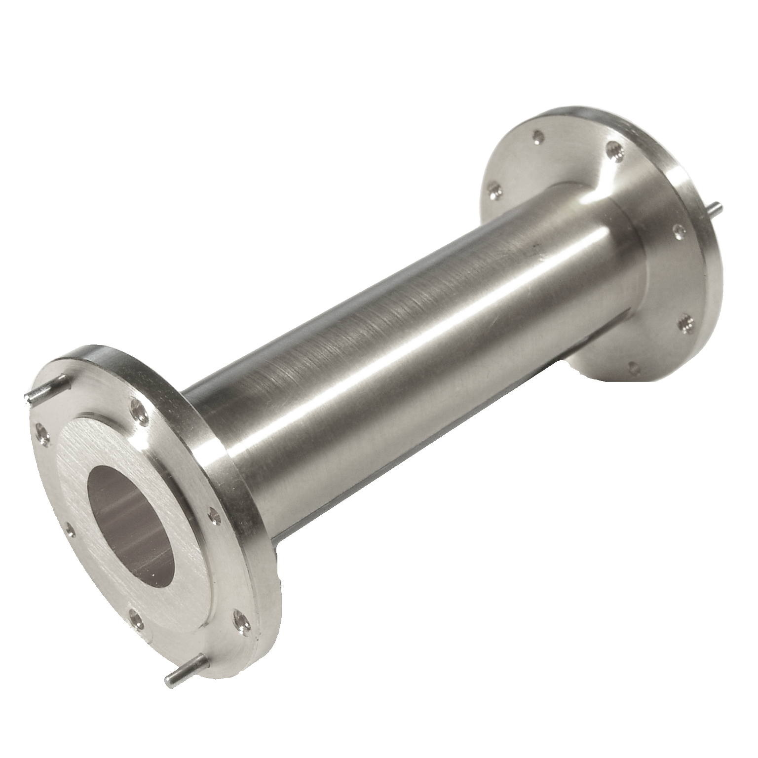
Mi-Wave’s Circular Waveguides (370 Series flanged and 371 Series unflanged) are precision-engineered transmission components designed to support low-loss RF signal propagation across microwave and millimeter-wave frequency bands from 12.6 GHz to 320 GHz.
Manufactured primarily from high-conductivity copper, these waveguides provide excellent electrical performance, mechanical stability, and repeatability in demanding RF environments. The 370 Series incorporates standard male/female flanges for easy integration into waveguide assemblies, while the 371 Series offers unflanged configurations for custom integration and specialized system requirements.
Circular waveguides support multiple propagation modes, most notably TE11 and TE01, enabling flexibility in system design. The TE11 mode is commonly used for general signal transmission, while the TE01 mode is preferred in applications requiring extremely low loss and high power handling, such as long-distance transmission and millimeter-wave systems.
Due to the non-standardized nature of circular waveguides, dimensions, tolerances, and performance characteristics may vary depending on the application. Mi-Wave works closely with customers to ensure proper sizing, mode selection, and integration for optimal system performance.
The standard models shown represent only part of Mi-Wave’s broader product capabilities. Custom configurations are available to support specific frequency bands, interfaces, and application requirements, enabling optimized solutions for specialized RF, microwave, and millimeter-wave systems.
Note: Our website contains just a few types of Circular Waveguides we build. Consult with us for your specific needs.
| Model | Band | Frequency (GHz) | Circular Waveguide Port Internal Diameter (inches) | Flange |
|---|---|---|---|---|
| 370X-.XXX/39 | X-Band | 8-9.97 8.5-11.6 9.7-12.4 | Option 1 1.094" ID Circular Waveguide Option 2 .938" ID Circular Waveguide Option 3 .797" ID Circular Waveguide | UG-39/U |
| 370Ku-.550/419 | Ku-Band | 12.4-14.6 14.6-17.5 | Option 1 .660" ID Circular Waveguide Option 2 .550" ID Circular Waveguide | UG-419/U |
| 370K-.328/595 | K-Band | 17.5- 20.5 20.5-24.5 24.5-26.5 | Option 1 .470" ID Circular Waveguide Option 2 .396" ID Circular Waveguide Option 3 .328" ID Circular Waveguide | UG-595/U |
| 370A-.XXX/599 | Ka-Band | 26.5-28.5 28.5-33 33-38.5 38.5-40 | Option 1 .328" ID Circular Waveguide Option 2 .281" ID Circular Waveguide Option 3 .250" ID Circular Waveguide Option 4 .219" ID Circular Waveguide | UG-599/U |
| 370B-.XXX/383 | Q-Band | 26.5-28.5 28.5-33 33-38.5 38.5-40 | Option 1 .250" ID Circular Waveguide Option 2 .219" ID Circular Waveguide Option 3 .188" ID Circular Waveguide | UG-383/U Flange |
| 370U-.219/383 | U-Band | 40-43 43-50 50-58 58-60 | Option 1 .219" ID Circular Waveguide Option 2 .188" ID Circular Waveguide Option 3 .165" ID Circular Waveguide Option 4 .141" ID Circular Waveguide | UG-383 |
| 370V-.XXX/385 | V-Band | 50-58 58-68 68-75 | Option 1 .165" ID Circular Waveguide Option 2 .141" ID Circular Waveguide Option 3 .125" ID Circular Waveguide | UG-385 |
| 370E-.XXX/387 | E-Band | 60-68 68-77 77-87 87-90 | Option 1 .141" ID Circular Waveguide Option 2 .125" ID Circular Waveguide Option 3 .110" ID Circular Waveguide Option 4 .094" ID Circular Waveguide | UG-387/U |
| 370W-.XXX/387 | W-Band | 75-77 77-87 87-100 100-110 | Option 1 .125" ID Circular Waveguide Option 2 .110" ID Circular Waveguide Option 3 .094" ID Circular Waveguide Option 4 .082" ID Circular Waveguide | UG-387/U-M |
| 370F-.XXX/387 | F-Band | 90-100 100-112 112-125 125-140 | Option 1 .094" ID Circular Waveguide Option 2 .082" ID Circular Waveguide Option 3 .075" ID Circular Waveguide Option 4 .067" ID Circular Waveguide | UG-387/U-M |
| 370D-.XXX/387 | D-Band | 110-112 112-125 125-160 160-170 | Option 1 .082" ID Circular Waveguide Option 2 .075" ID Circular Waveguide Option 3 .067" ID Circular Waveguide Option 4 .059" ID Circular Waveguide | UG-387/U-M |
| 370G-.XXX/387 | G-Band | 125-140 140-220 | Option 1 .067" ID Circular Waveguide Option 2 .059" ID Circular Waveguide | UG-387/U-M |
| 370H-.XXX/387 | H-Band | 170 | Option 1 .059" ID Circular Waveguide | UG-387/U-M |
| 370J-.049/387 | J-Band | 140-220 | Option 1 .049" ID Circular Waveguide | UG-387/U-M |
Features & Performance Characteristics
Low VSWR for Efficient Signal Transmission
Circular waveguides are designed to maintain excellent impedance matching, resulting in low VSWR and reduced reflections. This improves overall signal integrity and minimizes standing wave formation in high-frequency systems.
Precision Machining for Consistent Performance
Each waveguide section is manufactured with tight dimensional tolerances, ensuring predictable electromagnetic behavior. At microwave and millimeter-wave frequencies, even small variations can impact performance, making precision critical.
Support for Multiple Propagation Modes
Circular waveguides support both TE11 and TE01 modes, providing flexibility depending on system requirements. This allows engineers to optimize for either general transmission or ultra-low-loss performance.
Copper Construction for Low Loss
The use of high-conductivity copper minimizes resistive losses and supports efficient RF transmission across wide frequency ranges.
Flanged and Unflanged Configurations
The 370 Series includes precision flanged interfaces for standard connections, while the 371 Series allows for custom or embedded integration into assemblies and subsystems.
How They Work
Circular waveguides transmit RF energy by guiding electromagnetic waves through a hollow cylindrical conductor, allowing signals to propagate in specific field patterns known as modes.
Unlike coaxial cables, which rely on a center conductor, waveguides support field-based propagation, where energy travels through the interaction of electric and magnetic fields within the structure.
The most commonly used modes are:
- TE11 Mode
The dominant mode, used for general signal transmission due to its stable and efficient propagation characteristics. - TE01 Mode
A higher-order mode with significantly lower loss, often used in applications requiring maximum efficiency and high power handling.
For a signal to propagate, its frequency must be above the cutoff frequency of the selected mode. The diameter of the waveguide determines this cutoff, which is why different sizes are used to cover different frequency ranges.
Because there is no center conductor and the fields are distributed along the walls, circular waveguides offer lower loss and higher efficiency, especially at microwave and millimeter-wave frequencies.
Applications
Millimeter-Wave and Microwave Transmission Systems
Circular waveguides are widely used for low-loss signal transport in systems operating at high frequencies where traditional transmission lines become inefficient.
High-Power RF Systems
The TE01 mode is particularly suited for high-power applications, where reduced wall currents lead to lower losses and improved thermal performance.
Test and Measurement Environments
In RF laboratories and antenna test ranges, circular waveguides provide stable, repeatable transmission characteristics, supporting accurate measurements.
Satellite Communications and Radar Systems
Circular waveguides are used in advanced communication and radar systems where low attenuation and precise signal control are required.
Research and Development
Engineers and researchers rely on circular waveguides for experimental setups and mmWave development, especially when exploring mode behavior and propagation characteristics.
Frequently Asked Questions (FAQ)
What is a circular waveguide?
A circular waveguide is a hollow metallic tube that guides RF energy using electromagnetic field modes instead of a central conductor.
What is the difference between TE11 and TE01 modes?
TE11 is the dominant mode used for general transmission, while TE01 offers lower loss and higher power handling, making it ideal for specialized high-frequency applications.
Why use circular waveguides instead of rectangular waveguides?
Circular waveguides can support lower loss modes (like TE01) and are often preferred in applications requiring long-distance transmission or high power handling.
What frequency range do these waveguides support?
Mi-Wave circular waveguides cover frequencies from 12.6 GHz to 320 GHz, depending on size and configuration.
What is VSWR and why does it matter?
VSWR indicates how well the waveguide is matched to the system. Lower VSWR means less reflected power and better signal transmission.
Are these waveguides standardized?
Circular waveguides are less standardized than rectangular waveguides, so dimensions and performance may vary. Customization is often required.
Can Mi-Wave provide custom designs?
Yes. Mi-Wave works with customers to design waveguides tailored to specific frequency ranges, modes, and mechanical requirements.
Circular Waveguide Calculators
These calculators help estimate circular waveguide wavelength, cutoff frequency, and diameter relationships for microwave and millimeter-wave systems using TE11 and TE01 propagation modes.
Wavelength Calculator
Calculate free-space wavelength from operating frequency.
TE11 Cutoff Frequency
Estimate dominant TE11 cutoff frequency from circular waveguide diameter.
TE01 Cutoff Frequency
Estimate TE01 cutoff frequency from circular waveguide diameter.
Diameter for TE11 Cutoff
Estimate circular waveguide diameter needed for a desired TE11 cutoff frequency.
Diameter for TE01 Cutoff
Estimate circular waveguide diameter needed for a desired TE01 cutoff frequency.
Glossary of Circular Waveguide Terms
Circular Waveguide
A cylindrical transmission structure that guides RF energy using electromagnetic field modes.
TE Mode (Transverse Electric)
A propagation mode where the electric field is entirely transverse to the direction of propagation.
TE11 Mode
The dominant mode in circular waveguides, commonly used for standard signal transmission.
TE01 Mode
A low-loss mode with minimal wall current, often used in high-power or long-distance applications.
Cutoff Frequency
The minimum frequency required for a specific mode to propagate within the waveguide.
VSWR
A measure of impedance matching. Lower VSWR indicates better performance and reduced reflections.
Insertion Loss
The amount of signal attenuation as it passes through the waveguide.
Mode Conversion
The unintended transition from one propagation mode to another, which can degrade performance.
Waveguide Diameter
The physical dimension that determines cutoff frequency and supported modes.
Millimeter-Wave (mmWave)
Frequencies typically ranging from 30 GHz to 300 GHz.