

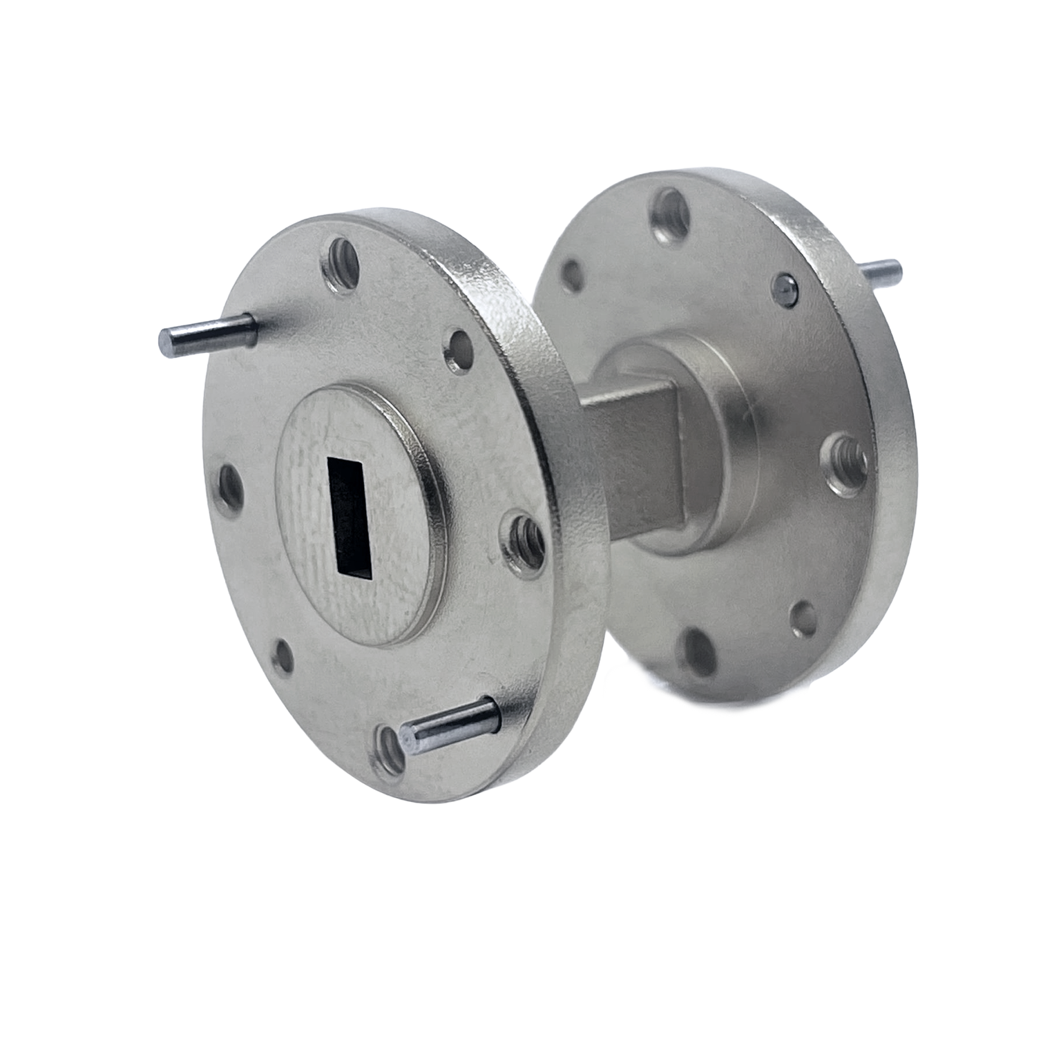
Mi-Wave’s 690 Series Flanged Waveguide Straight Sections are precision-fabricated transmission line components designed for low-loss RF signal routing across microwave and millimeter-wave systems. Available in standard waveguide sizes from 8 GHz to 500 GHz, these straight sections provide reliable waveguide connectivity for test setups, antenna systems, radar platforms, communication links, and integrated RF assemblies.
Each section is manufactured using MIL-SPEC waveguide and flanges, with careful control of fabrication processes to minimize discontinuities, distortion, and impedance mismatch. This helps preserve signal integrity, reduce reflections, and maintain stable RF performance across demanding high-frequency applications.
The 690 Series is available in a wide variety of materials, lengths, and flange configurations. Available lengths depend on raw waveguide stock, which varies by waveguide size. Longer sections, alternate materials, and special flanges are available upon request.
The standard models shown represent only part of Mi-Wave’s broader product capabilities. Custom configurations are available to support specific frequency bands, interfaces, and application requirements, enabling optimized solutions for specialized RF, microwave, and millimeter-wave systems.
*Actual product may be different from the image shown per customers specifcations
*All data presented is collected from a sample lot.
* Actual data may vary unit to unit, slightly.
*All testing was performed under +25 °C case temperature.
*Consult factory to confirm if material, plating, size, shape, orientation and any electrical parameter is critical for the application as website information is for reference only.
*Millimeter Wave Products, Inc. reserves the right to change the information presented on website without notice as we continue to enhance the performance and design of our products.
Features & Performance Characteristics
Precision MIL-SPEC Waveguide Construction
The 690 Series is fabricated using MIL-SPEC waveguide and flanges to provide dependable mechanical fit, alignment, and RF performance. This makes the sections suitable for high-frequency systems where dimensional accuracy directly affects transmission quality.
Low-Discontinuity RF Transmission
Precise fabrication helps eliminate waveguide discontinuities and distortion that can cause reflections, insertion loss, or mode conversion. This supports cleaner signal propagation through the waveguide path.
Broad Frequency Coverage
Available across standard waveguide sizes from 8 GHz to 500 GHz, the 690 Series supports a wide range of microwave, millimeter-wave, and sub-terahertz applications.
Multiple Material Options
Waveguide sections can be manufactured in a variety of materials depending on system requirements, including considerations for conductivity, weight, mechanical strength, corrosion resistance, and thermal behavior.
Custom Lengths and Flange Options
Standard lengths depend on available raw waveguide stock, but longer sections, special flanges, and custom mechanical configurations can be provided upon request.
Waveguide Straight Sections (Rectangular Waveguide)
Rectangular waveguide, like Mi-Wave’s 690 Series, is the preferred solution for high-frequency, high-power RF transmission. Instead of using a center conductor, waveguide propagates electromagnetic energy through a hollow metallic structure, resulting in very low loss and high power handling.
At frequencies above roughly 18 GHz and especially into mmWave bands, waveguide becomes significantly more efficient than coaxial cable. It also supports stable propagation modes, making it ideal for precision systems like radar, Satcom, and test environments.
Best for:
- Microwave and mmWave systems
- High-power transmission
- Low-loss signal paths
- Radar, Satcom, and RF test systems
How Waveguide Straight Sections Work
Waveguide straight sections guide electromagnetic energy through a hollow metallic transmission path. Unlike coaxial cable, a waveguide does not use a center conductor. Instead, RF energy propagates as electromagnetic field modes within the waveguide interior.
The geometry of the waveguide determines the operating frequency range and supported propagation modes. When the waveguide dimensions are properly matched to the operating band, RF energy travels efficiently with low loss and minimal reflection.
Straight sections are especially important because they establish the baseline transmission path between system components. Smooth internal surfaces, accurate dimensions, and precise flange alignment reduce discontinuities that could otherwise create impedance mismatch, standing waves, or mode conversion.
At microwave and millimeter-wave frequencies, small mechanical imperfections can significantly affect RF performance. This is why Mi-Wave’s 690 Series uses controlled fabrication processes and precision waveguide construction to maintain stable performance across demanding RF systems.
Applications
RF and Microwave Transmission Lines
Straight waveguide sections provide the primary transmission path between RF components, antennas, test equipment, and subsystem assemblies.
Millimeter-Wave Test Systems
In laboratory and production test environments, precision straight sections help maintain repeatable signal paths and minimize measurement uncertainty.
Radar and Communication Systems
Waveguide straight sections are used in radar, Satcom, and point-to-point communication systems where low-loss high-frequency routing is required.
Antenna Feed Networks
These components connect feed horns, OMTs, filters, bends, twists, and other waveguide devices in antenna and front-end assemblies.
Custom RF Subsystems
The 690 Series supports custom waveguide routing in compact or specialized RF systems requiring specific lengths, materials, or flange types.
Frequently Asked Questions (FAQ)
What is a waveguide straight section?
A waveguide straight section is a length of waveguide used to transmit RF energy between components in microwave and millimeter-wave systems.
What frequency range does the 690 Series support?
Mi-Wave’s 690 Series straight sections are available in standard waveguide sizes from 8 GHz to 500 GHz.
What materials are available?
The 690 Series is available in a variety of materials depending on application requirements. Contact Mi-Wave for material options based on waveguide size and operating environment.
Can custom lengths be made?
Yes. Available lengths depend on raw waveguide stock, but longer sections and custom lengths can be provided upon request.
Are special flanges available?
Yes. Special flange configurations are available upon request for custom system integration.
Why is precision fabrication important?
At high frequencies, small dimensional errors can create discontinuities, reflections, and signal distortion. Precision fabrication helps maintain low-loss, stable RF transmission.
Where are straight waveguide sections used?
They are used in RF test setups, antenna feeds, radar systems, communication links, millimeter-wave subsystems, and custom waveguide assemblies.
Interactive Waveguide Size Chart
Enter an operating frequency to quickly identify standard rectangular waveguide sizes that support that frequency range.
| Waveguide | Band | Frequency Range (GHz) | Inside Width (in) | Inside Height (in) |
|---|---|---|---|---|
| WR-90 | X | 8.2 – 12.4 | 0.900 | 0.400 |
| WR-75 | Ku | 10.0 – 15.0 | 0.750 | 0.375 |
| WR-62 | Ku | 12.4 – 18.0 | 0.622 | 0.311 |
| WR-51 | K | 15.0 – 22.0 | 0.510 | 0.255 |
| WR-42 | Ka | 18.0 – 26.5 | 0.420 | 0.170 |
| WR-34 | Ka | 22.0 – 33.0 | 0.340 | 0.170 |
| WR-28 | Ka | 26.5 – 40.0 | 0.280 | 0.140 |
| WR-22 | Q | 33.0 – 50.0 | 0.224 | 0.112 |
| WR-19 | U | 40.0 – 60.0 | 0.188 | 0.094 |
| WR-15 | V | 50.0 – 75.0 | 0.148 | 0.074 |
| WR-12 | E | 60.0 – 90.0 | 0.122 | 0.061 |
| WR-10 | W | 75.0 – 110.0 | 0.100 | 0.050 |
| WR-8 | F | 90.0 – 140.0 | 0.080 | 0.040 |
| WR-6 | D | 110.0 – 170.0 | 0.065 | 0.0325 |
| WR-5 | G | 140.0 – 220.0 | 0.051 | 0.0255 |
| WR-3.4 | Y | 220.0 – 330.0 | 0.034 | 0.017 |
| WR-2.8 | J | 260.0 – 400.0 | 0.028 | 0.014 |
| WR-2.2 | — | 330.0 – 500.0 | 0.022 | 0.011 |
Waveguide Straight Section Calculators
Estimate insertion loss, wavelength, electrical length, and phase shift for RF transmission through straight waveguide sections.
Insertion Loss Over Length
Estimate total loss through a straight waveguide section.
Wavelength Calculator
Calculate free-space wavelength for RF analysis.
Phase Shift
Estimate phase shift through waveguide length.
Electrical Length
Convert physical length to electrical degrees.
VSWR to Return Loss
Convert VSWR to return loss to evaluate reflections.
Glossary of Waveguide Straight Section Terms
Waveguide Straight Section
A straight length of waveguide used to route microwave or millimeter-wave energy between components.
Rectangular Waveguide
A hollow metallic transmission structure used to guide high-frequency RF signals.
Flanged Waveguide
Waveguide fitted with mechanical flanges for connection to other waveguide components.
MIL-SPEC Waveguide
Waveguide manufactured to military specification standards for dimensional and mechanical consistency.
Flange
The mechanical interface used to bolt waveguide sections and components together.
Discontinuity
An abrupt change in geometry or impedance that can cause reflections and signal distortion.
Insertion Loss
The signal loss introduced as RF energy passes through a component.
VSWR
Voltage Standing Wave Ratio, a measure of impedance matching and reflected power.
Mode Conversion
Unwanted conversion from one propagation mode to another due to imperfections or discontinuities.
Millimeter-Wave
Frequencies generally above 30 GHz where waveguide transmission is commonly used for low-loss routing.
Sub-Terahertz
Frequencies approaching or exceeding 300 GHz, often requiring highly precise waveguide components.
Signal Integrity
The preservation of signal quality as energy travels through an RF transmission path.
| Number | Band | Frequency (GHz) | VSWR (Typ) | RF Ports |
|---|---|---|---|---|
| 690X/39 | X-Band | 8.2-12.1 | 1.06:1 | WR-90 Waveguide, UG-39/U Flange |
| 690K/595 | K-Band | 18-26.5 | 1.06:1 | WR-42 Waveguide, UG-595/U Flange |
| 690A/599 | Ka-Band | 26.5-40 | 1.06:1 | WR-28 Waveguide, UG-599/U Flange |
| 690B/383 | Q-Band | 33-50 | 1.06:1 | WR-22 Waveguide, UG-383/U Flange |
| 690U/383 | U-Band | 40-60 | 1.12:1 | WR-19 Waveguide, UG-383/U Flange |
| 690V/385 | V-Band | 50-75 | 1.15:1 | WR-15 Waveguide, UG-385/U Flange |
| 690E/387 | E-Band | 60-90 | 1.15:1 | WR-12 Waveguide, UG-387/U Flange |
| 690W/387 | W-Band | 75-110 | 1.15:1 | WR-10 Waveguide, UG-387/U Flange |
| 690F/387 | F-Band | 90-140 | 1.15:1 | WR-8 Waveguide, UG-387/U Flange |
| 690D/387 | D-Band | 110-170 | 1.15:1 | WR-6 Waveguide, UG-387/U-M Flange |
| 690G/387 | G-Band | 140-220 | 1.15:1 | WR-5 Waveguide, UG-387/U Flange |
| 690H/387 | H-Band | 170-260 | 1.15:1 | WR-4 Waveguide, UG-387/U Flange |
| 690J/387 | J-Band | 220-325 | 1.15:1 | WR-3 Waveguide, UG-387/U Flange |
| 690(2.2)/387 | WR-2.2 | 325-500 | 1.15:1 | WR-2.2 Waveguide, UG-387/U Flange |
Interested in this product or other Mi-Wave solutions?
Contact our team to discuss your frequency range, interface needs, and application requirements.
Custom configurations are available for specialized RF, microwave, and millimeter-wave systems.
Return to Straight Waveguides Page
Return to Waveguides Page
Return to Products Page