

Mi-Wave’s Waveguide Twists (680 & 681 Series) are high-precision RF components designed to rotate the orientation of electromagnetic fields within a rectangular waveguide while maintaining efficient signal transmission. These twists enable controlled rotation of polarization and waveguide alignment without introducing significant loss or reflection.
The 680 Series consists of short sections of standard flanged waveguide with 45° twist configurations, available in left-hand or right-hand orientations, while the 681 Series provides 90° twist configurations for full orthogonal rotation.
The standard models shown represent only part of Mi-Wave’s broader product capabilities. Custom configurations are available to support specific frequency bands, interfaces, and application requirements, enabling optimized solutions for specialized RF, microwave, and millimeter-wave systems.
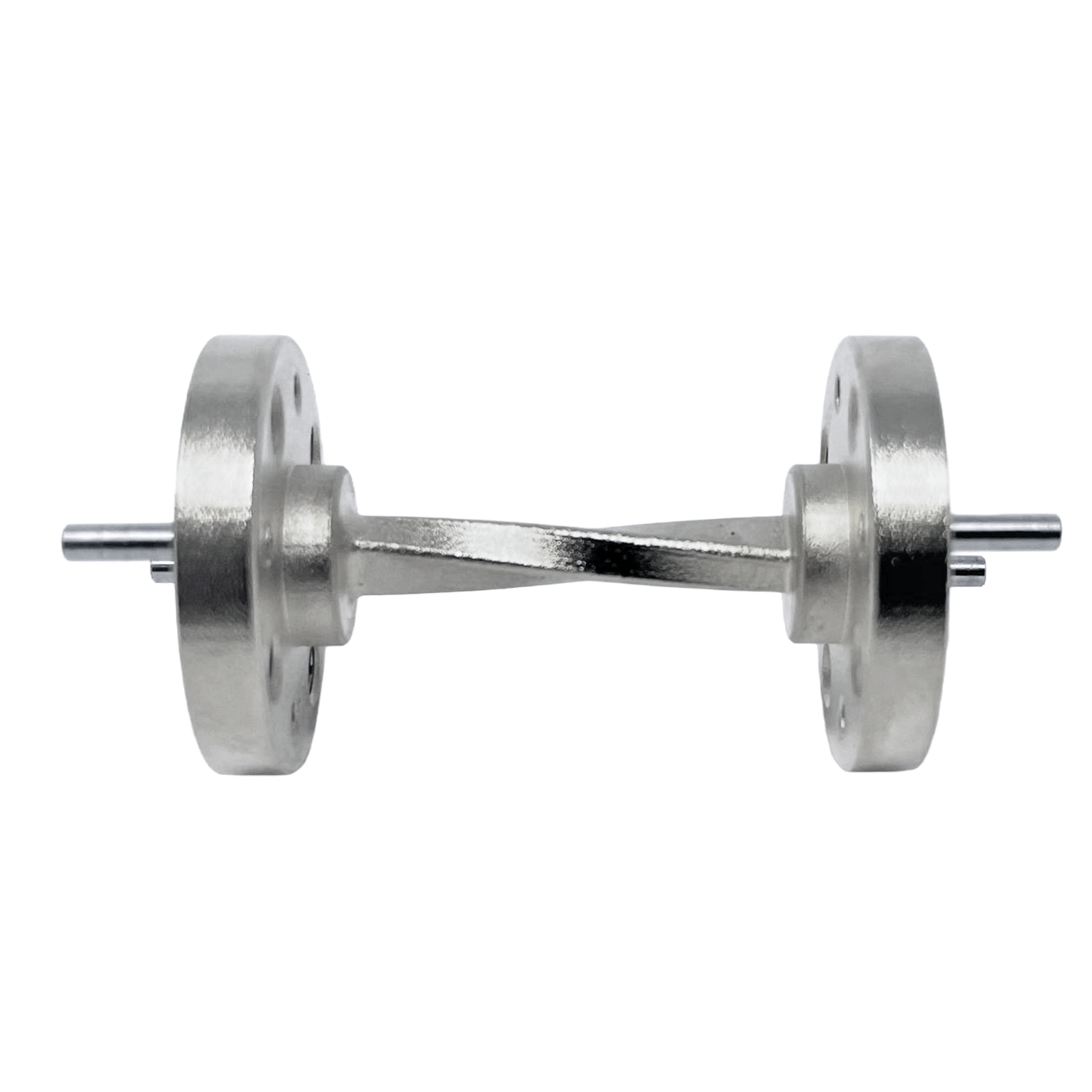
*Actual product may be different from the image shown per customers specifcations
*All data presented is collected from a sample lot.
* Actual data may vary unit to unit, slightly.
*All testing was performed under +25 °C case temperature.
*Consult factory to confirm if material, plating, size, shape, orientation and any electrical parameter is critical for the application as website information is for reference only.
*Millimeter Wave Products, Inc. reserves the right to change the information presented on website without notice as we continue to enhance the performance and design of our products.
Features & Performance Characteristics
Precise Polarization Rotation
Waveguide twists rotate the electromagnetic field orientation inside the waveguide without significantly disturbing signal propagation, enabling proper alignment between system components.
45° and 90° Twist Configurations
The 680 Series provides 45° twists, while the 681 Series provides 90° twists, allowing engineers to select the appropriate rotation for system requirements.
Left-Hand and Right-Hand Options
Twists are available in left-hand or right-hand configurations, giving flexibility in mechanical layout and field rotation direction.
Broad Frequency Coverage
Supporting frequencies from 8.2 GHz to 325 GHz, these twists are suitable for both microwave and millimeter-wave applications.
Low Loss and Minimal Reflection
Manufactured with precision tolerances, Mi-Wave twists are designed to minimize insertion loss and reduce reflections, preserving signal integrity across the operating band.
Standard Flanged Interfaces
Each unit uses standard flanged waveguide interfaces for easy integration into existing RF systems and assemblies.
How Waveguide Twists Work
Waveguide twists function by gradually rotating the cross-sectional orientation of the waveguide along its length. As the RF signal propagates through the twist, the electric and magnetic field components rotate with the physical geometry of the waveguide.
This controlled rotation allows the polarization of the signal to be reoriented without significantly disturbing the propagation mode. The twist must be carefully designed so that the transition is smooth, preventing mode conversion, reflections, or excessive insertion loss.
The direction of rotation, whether left-hand or right-hand, determines how the electromagnetic field is reoriented relative to the rest of the system. Proper selection ensures compatibility with downstream components such as antennas, OMTs, or ferrite devices.
Applications
Waveguide Orientation Alignment
Waveguide twists are used to align the orientation of waveguide components when mechanical layouts require rotation between sections.
Polarization Control
They are commonly used to rotate the polarization of RF signals to match antennas, orthomode transducers, or other polarization-sensitive components.
Ferrite Device Integration
Waveguide twists are often integrated into isolators, circulators, and other ferrite-based devices to properly align electromagnetic fields within the system.
Antenna Feed Systems
In antenna systems, twists ensure correct field orientation for efficient radiation and reception.
RF Test and Measurement Systems
Used in laboratory environments where waveguide routing and polarization control are required for accurate measurement setups.
Frequently Asked Questions (FAQ)
What is a waveguide twist?
A waveguide twist is a component that rotates the orientation of the electromagnetic field within a waveguide without significantly affecting signal transmission.
What twist angles are available?
Mi-Wave offers 45° twists (680 Series) and 90° twists (681 Series), with custom configurations available upon request.
What is the difference between left-hand and right-hand twists?
Left-hand and right-hand twists refer to the direction of rotation of the electromagnetic field as it travels through the waveguide. The correct choice depends on system alignment requirements.
What frequency range do these twists support?
Waveguide twists are available from 8.2 GHz to 325 GHz, depending on waveguide size and configuration.
Do waveguide twists affect signal performance?
When properly designed and manufactured, waveguide twists introduce minimal insertion loss and maintain low reflection levels.
Where are waveguide twists used?
They are used in antenna systems, ferrite devices, waveguide routing, RF test systems, and microwave or millimeter-wave subsystems.
Waveguide Twist Calculators
Calculate insertion loss impact, wavelength, phase shift, and polarization rotation effects when using waveguide twists in microwave and millimeter-wave systems.
Insertion Loss Through Twist
Estimate output power after waveguide twist insertion loss.
Wavelength Calculator
Calculate free-space wavelength for RF analysis.
Phase Shift Through Twist
Estimate phase shift based on electrical path length.
Polarization Rotation
Determine final polarization angle after twist.
VSWR to Return Loss
Convert VSWR to return loss for twist performance evaluation.
Glossary of Waveguide Twist Terms
Waveguide Twist
A waveguide component that rotates the electromagnetic field orientation along the propagation path.
Polarization Rotation
The rotation of the electric field orientation of an RF signal.
Left-Hand Twist
A twist where the field rotates in a left-hand (counterclockwise) direction along the propagation path.
Right-Hand Twist
A twist where the field rotates in a right-hand (clockwise) direction.
Insertion Loss
The amount of signal attenuation introduced by a component.
Mode Conversion
The unintended transition from one propagation mode to another, often caused by abrupt geometry changes.
Rectangular Waveguide
A metallic structure used to guide microwave and millimeter-wave signals.
Flanged Waveguide
A waveguide section with standardized mechanical interfaces for connection to other components.
Ferrite Devices
RF components such as isolators and circulators that rely on magnetic materials and often require precise field alignment.
Millimeter-Wave
Frequencies typically above 30 GHz where precision RF components are critical.
| Number | Band | Frequency (GHz) | Rotation | Configuration | VSWR (Typ) | RF Ports |
|---|---|---|---|---|---|---|
| 680X/39 | X-Band | 8.2-12.1 | 45° | Left or Right | 1.2 | WR-90 Waveguide, UG-39/U Flange |
| 680K/595 | K-Band | 18-26.5 | 45° | Left or Right | 1.06:1 | WR-42 Waveguide, UG-595/U Flange |
| 680A/599 | Ka-Band | 26.5-40 | 45° | Left or Right | 1.06:1 | WR-28 Waveguide, UG-599/U Flange |
| 680B/383 | Q-Band | 33-50 | 45° | Left or Right | 1.06:1 | WR-22 Waveguide, UG-383/U Flange |
| 680U/383 | U-Band | 40-60 | 45° | Left or Right | 1.12:1 | WR-19 Waveguide, UG-383/U Flange |
| 680V/385 | V-Band | 50-75 | 45° | Left or Right | 1.15:1 | WR-15 Waveguide, UG-385/U Flange |
| 680E/387 | E-Band | 60-90 | 45° | Left or Right | 1.15:1 | WR-12 Waveguide, UG-387/U Flange |
| 680W/387 | W-Band | 75-110 | 45° | Left or Right | 1.15:1 | WR-10 Waveguide, UG-387/U Flange |
| 680F/387 | F-Band | 90-140 | 45° | Left or Right | 1.15:1 | WR-8 Waveguide, UG-387/U Flange |
| 680D/387 | D-Band | 110-170 | 45° | Left or Right | 1.15:1 | WR-6 Waveguide, UG-387/U-M Flange |
| 680G/387 | G-Band | 140-220 | 45° | Left or Right | 1.15:1 | WR-5 Waveguide, UG-387/U Flange |
| 680H/387 | H-Band | 170-260 | 45° | Left or Right | 1.15:1 | WR-4 Waveguide, UG-387/U Flange |
| 680J/387 | J-Band | 220-325 | 45° | Left or Right | 1.15:1 | WR-3 Waveguide, UG-387/U Flange |
| 681X/39 | X-Band | 8.2-12.1 | 90° | Left or Right | 1.06:1 | WR-90 Waveguide, UG-39/U Flange |
| 681K/595 | K-Band | 18-26.5 | 90° | Left or Right | 1.06:1 | WR-42 Waveguide, UG-595/U Flange |
| 681A/599 | Ka-Band | 26.5-40 | 90° | Left or Right | 1.06:1 | WR-28 Waveguide, UG-599/U Flange |
| 681B/383 | Q-Band | 33-50 | 90° | Left or Right | 1.06:1 | WR-22 Waveguide, UG-383/U Flange |
| 681U/383 | U-Band | 40-60 | 90° | Left or Right | 1.12:1 | WR-19 Waveguide, UG-383/U Flange |
| 681V/385 | V-Band | 50-75 | 90° | Left or Right | 1.15:1 | WR-15 Waveguide, UG-385/U Flange |
| 681E/387 | E-Band | 60-90 | 90° | Left or Right | 1.15:1 | WR-12 Waveguide, UG-387/U Flange |
| 681W/387 | W-Band | 75-110 | 90° | Left or Right | 1.15:1 | WR-10 Waveguide, UG-387/U Flange |
| 681F/387 | F-Band | 90-140 | 90° | Left or Right | 1.15:1 | WR-8 Waveguide, UG-387/U Flange |
| 681D/387 | D-Band | 110-170 | 90° | Left or Right | 1.15:1 | WR-6 Waveguide, UG-387/U-M Flange |
| 681G/387 | G-Band | 140-220 | 90° | Left or Right | 1.15:1 | WR-5 Waveguide, UG-387/U Flange |
| 681H/387 | H-Band | 170-260 | 90° | Left or Right | 1.15:1 | WR-4 Waveguide, UG-387/U Flange |
| 681J/387 | J-Band | 220-325 | 90° | Left or Right | 1.15:1 | WR-3 Waveguide, UG-387/U Flange |
Return to Bends & Twists Page