

Description:
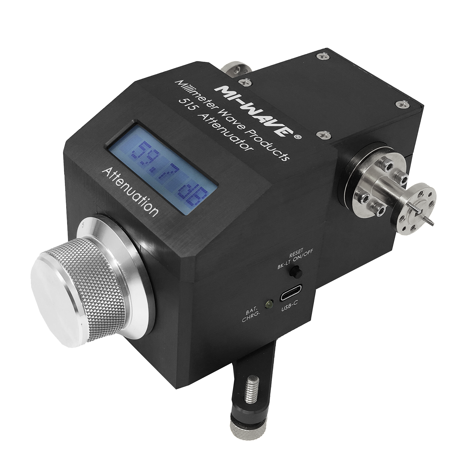
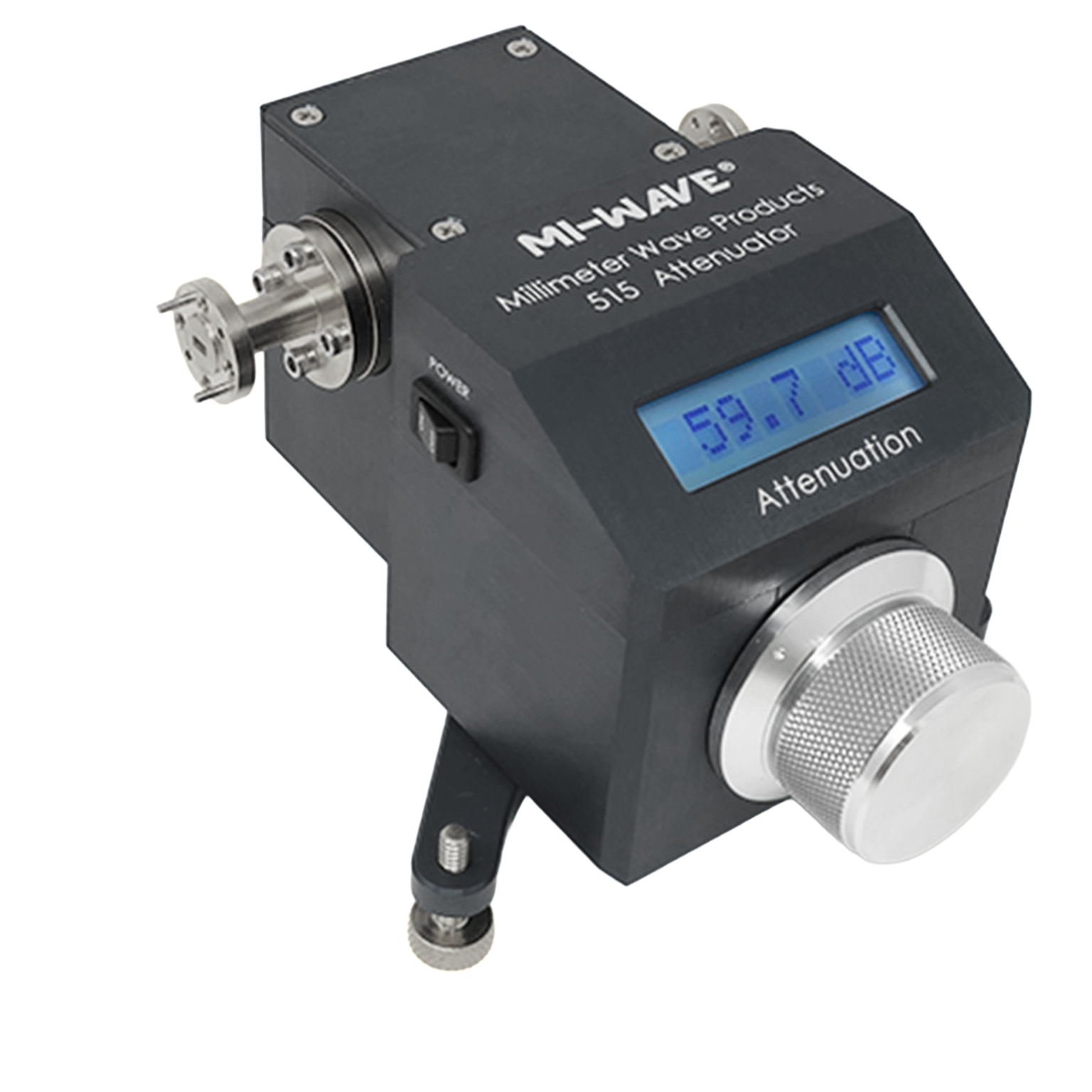
Mi-Wave’s 515 Series Direct-reading electronic Precision Attenuators provide 0 to 60 dB of calibrated attenuation by rotation of a resistive vane mounted in a circular waveguide section. These units are often referred to as precision rotary vane attenuators.
Features
• High Accuracy to 60dB
• Low VSWR
• Direct Reading
• Low Insertion Loss
• Anti-backlash Drive
• Negligible Phase Shift
• Rechargeable Internal Battery using USB C cable
• Battery Life 40 Hours
Applications
• Test & Measurement
• Manual Test Setups
• Mobile & Satellite Communications
• Radar Systems
The standard models shown represent only part of Mi-Wave’s broader product capabilities. Custom configurations are available to support specific frequency bands, interfaces, and application requirements, enabling optimized solutions for specialized RF, microwave, and millimeter-wave systems.
*Actual product may be different from the image shown per customers specifcations
*All data presented is collected from a sample lot.
* Actual data may vary unit to unit, slightly.
*All testing was performed under +25 °C case temperature.
*Consult factory to confirm if material, plating, size, shape, orientation and any electrical parameter is critical for the application as website information is for reference only.
*Millimeter Wave Products, Inc. reserves the right to change the information presented on website without notice as we continue to enhance the performance and design of our products.
Features & Specifications
Mi-Wave’s 515 Series Direct-Reading Electronic Precision Attenuators are engineered to deliver accurate, stable, and repeatable attenuation across microwave and millimeter-wave systems.
Direct-Reading Attenuation Control
Provides calibrated attenuation through a precision mechanical rotation mechanism, allowing users to set attenuation levels directly without external measurement verification.
Attenuation Range: 0 to 60 dB
Offers a wide dynamic range for signal control, calibration, and receiver testing applications.
High Accuracy Performance
Designed for precision applications requiring consistent and repeatable attenuation settings across the full attenuation range.
Low VSWR
Maintains good impedance matching to minimize signal reflections and ensure measurement reliability.
Low Insertion Loss
Minimizes additional signal loss beyond the intended attenuation, preserving signal integrity in high-frequency systems.
Negligible Phase Shift
Engineered to introduce minimal phase variation, making it suitable for sensitive measurement and calibration applications.
Anti-Backlash Drive Mechanism
Ensures smooth, precise, and repeatable attenuation adjustments without mechanical play or drift.
Rechargeable Internal Battery (USB-C)
Powered by a built-in rechargeable battery, allowing portable operation without the need for continuous external power.
Battery Life: Up to 40 Hours
Supports extended use in laboratory or field environments without frequent recharging.
Circular Waveguide Design
Utilizes a resistive vane in a circular waveguide section for stable, mode-free attenuation performance.
Applications
Mi-Wave’s 515 Series Direct-Reading Electronic Precision Attenuators are used in RF, microwave, and millimeter-wave systems where accurate, portable, and repeatable attenuation control is required.
RF & Microwave Test Systems
Provides precise signal level control during testing of amplifiers, receivers, and microwave subsystems.
Calibration & Metrology Laboratories
Ideal for environments requiring repeatable attenuation settings and measurement accuracy, supporting instrument calibration and validation workflows.
Portable RF Testing
With its internal rechargeable battery, the 515 Series is well suited for field testing and mobile RF measurement setups.
Signal Conditioning in Waveguide Systems
Used to control signal levels between RF components to prevent overload and maintain proper system performance.
Receiver Sensitivity Testing
Allows engineers to reduce signal levels in a controlled manner to evaluate receiver thresholds and dynamic range.
Engineering Development & R&D
Supports system tuning, prototyping, and troubleshooting in microwave and mmWave design environments.
Aerospace & Defense Systems
Applicable to radar, communications, and electronic warfare systems where stable and repeatable attenuation is critical.
Frequently Asked Questions (FAQ)
What is a direct-reading electronic precision attenuator?
A direct-reading electronic precision attenuator is a device that provides calibrated attenuation through a mechanical adjustment mechanism, often enhanced with electronic features such as digital readout or battery-powered operation.
What is the attenuation range of the 515 Series?
The 515 Series provides 0 to 60 dB of calibrated attenuation.
How is attenuation adjusted in the 515 Series?
Attenuation is controlled by rotating a resistive vane within a circular waveguide section, providing smooth and repeatable signal reduction.
Does the 515 Series require external power?
No. It features a rechargeable internal battery that can be charged via USB-C, enabling portable operation.
How long does the battery last?
The internal battery provides up to 40 hours of operation depending on usage.
What are the advantages of a rotary vane attenuator design?
Rotary vane attenuators provide smooth attenuation control, high accuracy, low insertion loss, and minimal phase shift, making them ideal for precision RF applications.
Is the 515 Series suitable for calibration applications?
Yes. Its high accuracy, repeatability, and direct-reading capability make it well suited for calibration and metrology environments.
RF Attenuator Calculators
These RF attenuator calculators are designed to support microwave and millimeter-wave engineers working with direct reading precision attenuators, waveguide attenuators, and laboratory RF test setups. Use these tools to quickly convert attenuation values, estimate power levels, evaluate cascaded loss, and analyze impedance match performance for systems spanning X-Band through J-Band.
dB to Power Ratio
Convert attenuation or gain in decibels to a linear power ratio.
Power Ratio to dB
Convert a linear power ratio into decibels.
dBm to Watts
Convert RF power in dBm to watts for test and system-level calculations.
Watts to dBm
Convert watts to dBm for RF signal level analysis.
Cascaded Attenuation Calculator
Add multiple attenuator values together to determine total path attenuation.
VSWR to Return Loss
Estimate return loss from a known VSWR value.
Glossary of Direct-Reading Electronic Attenuator Terms
Attenuator Fundamentals
Direct-Reading Attenuator
An attenuator that allows users to set attenuation levels using a calibrated scale without external measurement equipment.
Rotary Vane Attenuator
An attenuator that uses a rotating resistive vane inside a waveguide to control signal attenuation.
Precision Attenuator
An attenuator designed for accurate, repeatable signal reduction in measurement and calibration environments.
Electrical Performance
Attenuation (dB)
The reduction of signal power expressed in decibels.
Insertion Loss
The signal loss introduced by a device beyond the intended attenuation.
VSWR (Voltage Standing Wave Ratio)
A measure of impedance matching and signal reflection in an RF system.
Phase Shift
The change in phase of a signal as it passes through a device.
Negligible Phase Shift
Minimal phase variation introduced by a component, important for maintaining measurement accuracy.
RF and Frequency
Radio Frequency (RF)
Electromagnetic signals used for communication, sensing, and measurement.
Microwave Frequencies
Frequencies typically ranging from 1 GHz to 30 GHz.
Millimeter-Wave (mmWave)
Frequencies above 30 GHz used in advanced RF systems.
Mechanical and Design
Resistive Vane
A lossy element inserted into a waveguide to control signal attenuation.
Circular Waveguide
A waveguide structure with a circular cross-section used for stable RF propagation.
Anti-Backlash Drive
A mechanical system designed to eliminate play or looseness in movement, ensuring precise adjustment.
Power and Operation
Rechargeable Internal Battery
A built-in power source that allows the attenuator to operate without external power.
USB-C Charging
A modern power interface used for charging the internal battery.
Portable Operation
The ability to operate the device independently of fixed power sources.
System and Applications
Calibration
The process of verifying measurement accuracy using known reference standards.
Signal Conditioning
Adjusting signal levels to meet system requirements.
Receiver Sensitivity Testing
Testing the minimum signal level a receiver can detect.
RF Test & Measurement
The evaluation of RF system performance using specialized equipment.
Note: Our website contains just a few types of Attenuators we build. Consult with us for your specific needs.
| Model | Minimum Frequency (GHz) | Maximum Frequency (GHz) | Insertion Loss (dB) typical | Attenuation Range (dB) | Resolution (dB) | Power Handling (Watts) | RF Ports | Accuracy | LINK |
|---|---|---|---|---|---|---|---|---|---|
| 515Ku/419 | 12.4 | 18 | 0.5 | 0-60 | 0.01 | 0.3 | WR-62 Waveguide with UG-419/U Flanges | 0.1 dB or less than 1% of setting | |
| 515K/595 | 18 | 26.5 | 0.5 | 0-60 | 0.01 | 0.3 | WR-42 Waveguide with UG-595/U Flanges | 0.1 dB or less than 1% of setting | |
| 515(34)/595 | 22 | 33 | 0.5 | 0-60 | 0.01 | 0.2 | WR-34 Waveguide with UG-595/U Flanges | 0.1 dB or less than 1% of setting | |
| 515A/599 | 26.5 | 40 | 0.5 | 0-60 | 0.01 | 10 | WR-28 Waveguide, UG-599/U Flange | 0.1 dB or less than 1% of setting | |
| 515B/383 | 33 | 50 | 0.7 | 0-60 | 0.01 | 7 | WR-22 Waveguide, UG-383/U Flange | 0.1 dB or less than 1% of setting | |
| 515U/383 | 40 | 60 | 1.0 | 0-60 | 0.01 | 5 | WR-19 Waveguide, UG-383/U-M Flange | 0.1 dB or less than 1% of setting | |
| 515V/385 | 50 | 75 | 1.2 | 0-60 | 0.01 | 5 | WR-15 Waveguide, UG-385/U Flange | 0.1 dB or less than 1% of setting | |
| 515E/387 | 60 | 90 | 1.8 | 0-60 | 0.01 | 2 | WR-12 Waveguide, UG-387/U Flanges | 0.1 dB or less than 1% of setting | |
| 515W/387 | 75 | 110 | 3.3 | 0-60 | 0.01 | 2 | WR-10 Waveguide, UG-387/U-M Flanges | 0.1 dB or less than 1% of setting | |
| 515F/387 | 90 | 140 | 3.4 | 0-60 | 0.01 | 0.1 | WR-08 Waveguide, UG-387/U-M Flange | 0.1 dB or less than 1% of setting | |
| 515D/387 | 110 | 170 | 3.5 | 0-60 | 0.01 | 0.1 | WR-06 Waveguide, UG-387/U-M Flange | 0.1 dB or less than 1% of setting | |
| 515G/387 | 140 | 220 | 3.8 | 0-60 | 0.01 | 0.1 | WR-05 Waveguide, UG-387/U-M Flange | 0.1 dB or less than 1% of setting |
High Accuracy Direct-Reading Precision Electronic Attenuator
Key features include:
-Accuracy and resolution has been dramatically improved for better performance.
-Attenuation from 0-60 dB: Up to to 60dB Attenuation (above for reference only) & a High Accuracy of 0.1 db or < 1% of the setting. A digital readout is provided on the front panel to display attenuation settings.
-USB Ready: Operates off a standard USB C cable that will charge the battery
The 515 Series Direct-reading Precision attenuators are used in all RF measurement systems. They are most frequently used in RF substitution-type set-ups for precise measurement of characteristics such as isolation, coupling, insertion loss and gain
Note:
Lower frequency versions are available from 8.4 GHz and up.
Accuracy is based on calibration of test equipment.
Other Band/Waveguide Sizes available
WR-137
WR-112
WR-90
WR-75
WR-62
WR-51
WR-3