

Product Description
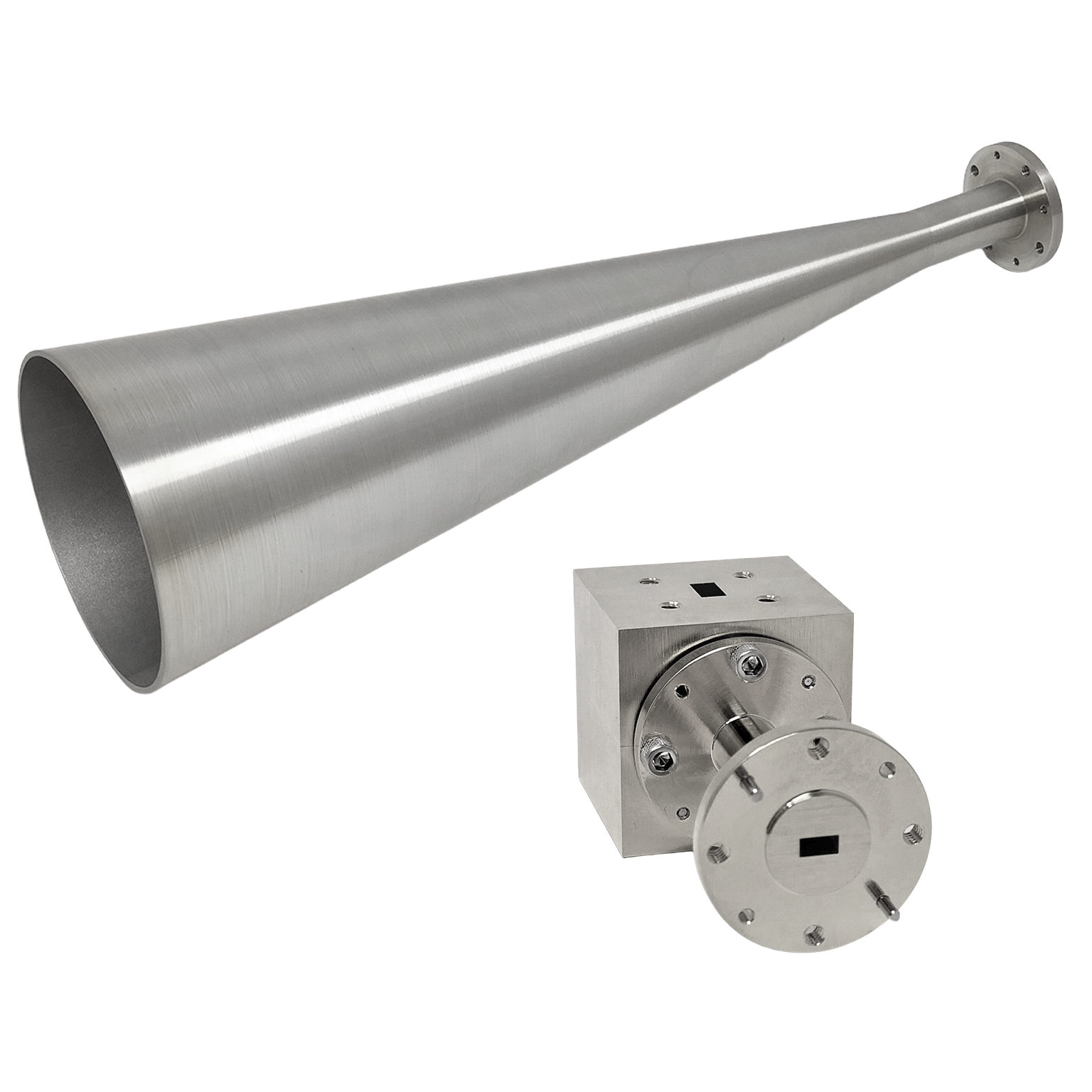
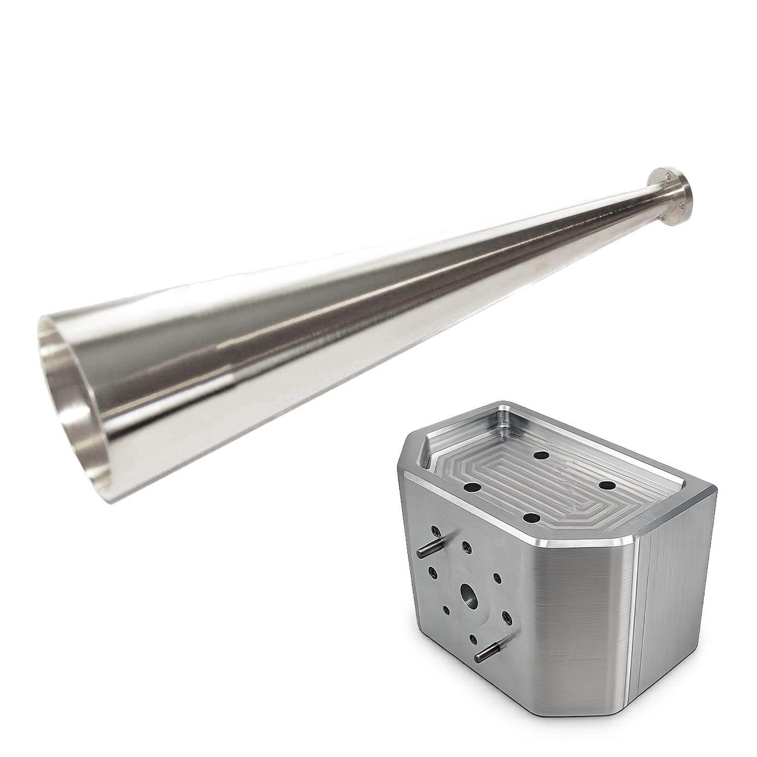
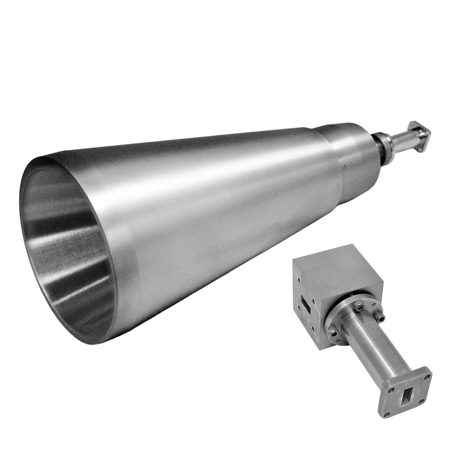
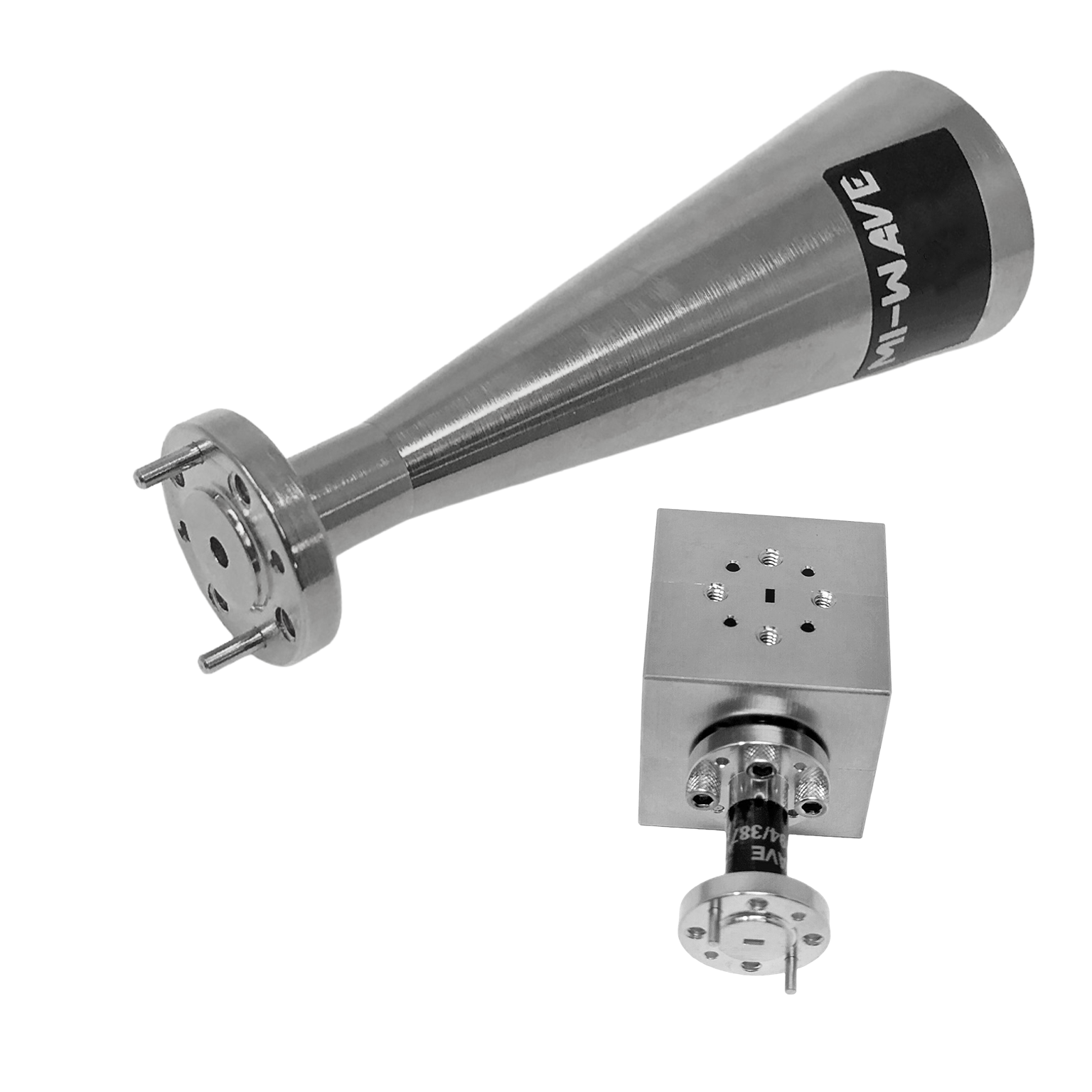
Mi-Wave’s Dual-Polarized Conical Horn Antennas, including the Series 262, are precision-engineered wideband antennas designed to deliver smooth radiation patterns, reliable directivity, stable polarization performance, and broadband frequency coverage across RF, microwave, and millimeter-wave applications from 8.2 to 325 GHz.
These antennas use a circular waveguide with a conical flare to efficiently transition electromagnetic energy into free space. The symmetrical conical geometry supports stable gain, balanced radiation characteristics, low insertion loss, and low VSWR across a wide operating band.
For dual-polarized operation, Series 262 Conical Horn Antennas can be integrated with Mi-Wave’s Series 281 Orthomode Transducer (OMT) to support separate Vertical (V) and Horizontal (H) polarization paths through the same antenna aperture. This allows two orthogonal RF channels to transmit or receive simultaneously while maintaining high isolation between polarization channels.
Conical horn antennas are ideal for systems requiring predictable beam shape, broadband impedance matching, repeatable performance, and stable polarization behavior. Their symmetrical radiation pattern and wideband response make them well suited for communications systems, radar platforms, antenna measurement ranges, RF test environments, and advanced research applications.
The models shown represent only a portion of Mi-Wave’s full capabilities. Custom conical horn antenna designs are available to support specific frequency bands, waveguide sizes, polarization requirements, OMT integration, and mechanical configurations.
RF Orthomode Transducers
The standard models shown represent only part of Mi-Wave’s broader product capabilities. Custom configurations are available to support specific frequency bands, interfaces, and application requirements, enabling optimized solutions for specialized RF, microwave, and millimeter-wave systems.
| Waveguide Band | Model No. | Gain (dBi) | Circular Waveguide Internal Diameter (.XXX in Model No.) in Inches | Frequency Range (GHz) | 3 dB Beamwidth E-Plane (Degrees °) | 3dB Beamwidth (degree) H-plane | Polarization | VSWR | Antenna Port | Link |
|---|---|---|---|---|---|---|---|---|---|---|
| X-band | 262X-15/.XXX/39-DP | 10 | .XXX=1.094 .XXX=.938 .XXX= .797 | 8.2-9.97 8.5-11.6 9.97-12.4 | 59.42 | 57.7 | Vertical | Horizontal | 1.3:1 | Circular Waveguide with UG-39/U Flange | |
| X-band | 262X-15/.XXX/39-DP | 15 | .XXX=1.094 .XXX=.938 .XXX= .797 | 8.2-9.97 8.5-11.6 9.97-12.4 | 15.28 | 18.54 | Vertical | Horizontal | 1.3:1 | Circular Waveguide with UG-39/U Flange | |
| Ku-Band | 262KU-10/.XXX/419-DP | 10 | XXX=.660 XXX=.550 | 12.4-14.6 14.6-18.0 | 47.67 | 50.04 | Vertical | Horizontal | 1.3:1 | Circular Waveguide with UG-419/U Flange | |
| Ku-Band | 262KU-10/.XXX/419-DP | 15 | XXX=.660 XXX=.550 | 12.4-14.6 14.6-18.0 | 28.25 | 32.96 | Vertical | Horizontal | 1.3:1 | Circular Waveguide with UG-419/U Flange | |
| K-Band | 262K-10/.XXX/595-DP | 10 | XXX=.470 XXX .396 XXX=.328 | 18.0-20.5 20.4-24.5 24.5-26.5 | 45.72 | 48.54 | Vertical | Horizontal | 1.3:1 | Circular Waveguide with UG-595/U Flange or UG-425/U Flange | |
| K-Band | 262K-15/.XXX/595-DP | 15 | XXX=.470 XXX .396 XXX=.328 | 18.0-20.5 20.4-24.5 24.5-26.5 | 26.5 | 31.13 | Vertical | Horizontal | 1.3:1 | Circular Waveguide with UG-595/U Flange or UG-425/U Flange | |
| K-Band | 262K-20/.XXX/595-DP | 20 | XXX=.470 XXX .396 XXX=.328 | 18.0-20.5 20.4-24.5 24.5-26.5 | 14.48 | 17.61 | Vertical | Horizontal | 1.3:1 | Circular Waveguide with UG-595/U Flange or UG-425/U Flange | |
| Ka-Band | 262A-10/.XXX/599-DP | 10 | XXX=.328 XXX=.281 XXX=.250 XXX= .219 | 26.5-28.5 28.5-33.0 33.0 -38.5 38.5-40.0 | 47.64 | 49.03 | Vertical | Horizontal | 1.3:1 | Circular Waveguide with UG-599/U Flange or UG-381/U Flange | |
| Ka-Band | 262A-15/.XXX/599-DP | 15 | XXX=.328 XXX=.281 XXX=.250 XXX= .219 | 26.5-28.5 28.5-33.0 33.0 -38.5 38.5-40.0 | 23.44 | 27.94 | Vertical | Horizontal | 1.3:1 | Circular Waveguide with UG-599/U Flange or UG-381/U | |
| Ka-Band | 262A-20/.XXX/599-DP | 20 | XXX=.328 XXX=.281 XXX=.250 XXX= .219 | 26.5-28.5 28.5-33.0 33.0 -38.5 38.5-40.0 | 15.9 | 19.39 | Vertical | Horizontal | 1.3:1 | Circular Waveguide with UG-599/U Flange or UG-381/U | |
| Ka-Band | 262A-25/.XXX/599-DP | 25 | XXX=.328 XXX=.281 XXX=.250 XXX= .219 | 26.5-28.5 28.5-33.0 33.0 -38.5 38.5-40.0 | 8.62 | 10.55 | Vertical | Horizontal | 1.3:1 | Circular Waveguide with UG-599/U Flange or UG-381/U | |
| Q-Band | 262B-10/.XXX/383-DP | 10 | XXX=.250 XXX=.219 XXX=.188 | 33.0-38.5 38.5-43.0 43.0-50.0 | 49.92 | 51.66 | Vertical | Horizontal | 1.3:1 | Circular Waveguide with UG-383/U Flange | |
| Q-Band | 262B-15/.XXX/383-DP | 15 | XXX=.250 XXX=.219 XXX=.188 | 33.0-38.5 38.5-43.0 43.0-50.0 | 25.27 | 29.88 | Vertical | Horizontal | 1.3:1 | Circular Waveguide with UG-383/U Flange | |
| Q-Band | 263B-20/.XXX/383-DP | 20 | XXX=.250 XXX=.219 XXX=.188 | 33.0-38.5 38.5-43.0 43.0-50.0 | 14.36 | 17.56 | Vertical | Horizontal | 1.3:1 | Circular Waveguide with UG-383/U Flange | |
| Q-Band | 262B-25/.XXX/383-DP | 25 | XXX=.250 XXX=.219 XXX=.188 | 33.0-38.5 38.5-43.0 43.0-50.0 | 8.23 | 9.96 | Vertical | Horizontal | 1.3:1 | Circular Waveguide with UG-383/U Flange | |
| U-Band | 262U-10/.XXX/383-DP | 10 | XXX=.219 XXX=.188 XXX=.165 XXX=.141 | 38.5-43.0 43.0-50.0 50.0-58.0 58.0-60.0 | 54.64 | 54.84 | Vertical | Horizontal | 1.3:1 | Circular Waveguide with UG-383/U-M Flange | |
| U-Band | 262U-15/.XXX/383-DP | 15 | XXX=.219 XXX=.188 XXX=.165 XXX=.141 | 38.5-43.0 43.0-50.0 50.0-58.0 58.0-60.0 | 29.53 | 34.39 | Vertical | Horizontal | 1.3:1 | Circular Waveguide with UG-383/U-M Flange | |
| U-Band | 262U-20/.XXX/383-DP | 20 | XXX=.219 XXX=.188 XXX=.165 XXX=.141 | 38.5-43.0 43.0-50.0 50.0-58.0 58.0-60.0 | 12.34 | 15.17 | Vertical | Horizontal | 1.3:1 | Circular Waveguide with UG-383/U-M Flange | |
| U-Band | 262U-25/.XXX/383-DP | 25 | XXX=.219 XXX=.188 XXX=.165 XXX=.141 | 38.5-43.0 43.0-50.0 50.0-58.0 58.0-60.0 | 8.78 | 10.76 | Vertical | Horizontal | 1.3:1 | Circular Waveguide with UG-383/U-M Flange | |
| V-Band | 262V-10/.XXX/385-DP | 10 | XXX=.165 XXX=.141 XXX=.125 | 50.0-58.0 58.0-68.0 68.0-75.0 | 55.99 | 55.68 | Vertical | Horizontal | 1.3:1 | Circular Waveguide with UG-385/U Flange | |
| V-Band | 262V-15/.XXX/385-DP | 15 | XXX=.165 XXX=.141 XXX=.125 | 50.0-58.0 58.0-68.0 68.0-75.0 | 29.69 | 34.56 | Vertical | Horizontal | 1.3:1 | Circular Waveguide with UG-385/U Flange | |
| V-Band | 262V-20/.XXX/385-DP | 20 | XXX=.165 XXX=.141 XXX=.125 | 50.0-58.0 58.0-68.0 68.0-75.0 | 15.22 | 18.64 | Vertical | Horizontal | 1.3:1 | Circular Waveguide with UG-385/U Flange | |
| V-Band | 262V-25/.XXX/385-DP | 25 | XXX=.165 XXX=.141 XXX=.125 | 50.0-58.0 58.0-68.0 68.0-75.0 | 7.68 | 9.32 | Vertical | Horizontal | 1.3:1 | Circular Waveguide with UG-385/U Flange | |
| E-Band | 262E-10/.XXX/387-DP | 10 | XXX=.141 XXX=.125 XXX=.110 XXX=.094 | 60.0-68.0 68.0-77.0 77.0-87.0 87.0-90.0 | 51.39 | 52.7 | Vertical | Horizontal | 1.3:1 | Circular Waveguide with UG-387/U Flange | |
| E-Band | 262E-15/.XXX/387-DP | 15 | XXX=.141 XXX=.125 XXX=.110 XXX=.094 | 60.0-68.0 68.0-77.0 77.0-87.0 87.0-90.0 | 28.39 | 33.22 | Vertical | Horizontal | 1.3:1 | Circular Waveguide with UG-387/U Flange | |
| E-Band | 262E-20/.XXX/387-DP | 20 | XXX=.141 XXX=.125 XXX=.110 XXX=.094 | 60.0-68.0 68.0-77.0 77.0-87.0 87.0-90.0 | 15.59 | 18.97 | Vertical | Horizontal | 1.3:1 | Circular Waveguide with UG-387/U Flange | |
| E-Band | 262E-25/.XXX/387-DP | 25 | XXX=.141 XXX=.125 XXX=.110 XXX=.094 | 60.0-68.0 68.0-77.0 77.0-87.0 87.0-90.0 | 8 | 9.74 | Vertical | Horizontal | 1.3:1 | Circular Waveguide with UG-387/U Flange | |
| W-Band | 262W-10/.XXX/387-DP | 10 | XXX=.125 XXX=.110 XXX=.094 XXX=.082 | 75.0-77.0 77.0-87.0 87.0-100.0 100.0-110.0 | 60.48 | 58.32 | Vertical | Horizontal | 1.3:1 | Circular Waveguide with UG-387/U-M Flange | |
| W-Band | 262W-15/.XXX/387-DP | 15 | XXX=.125 XXX=.110 XXX=.094 XXX=.082 | 75.0-77.0 77.0-87.0 87.0-100.0 100.0-110.0 | 29.86 | 34.73 | Vertical | Horizontal | 1.3:1 | Circular Waveguide with UG-387/U-M Flange | |
| W-Band | 262W-20/.XXX/387-DP | 20 | XXX=.125 XXX=.110 XXX=.094 XXX=.082 | 75.0-77.0 77.0-87.0 87.0-100.0 100.0-110.0 | 16.33 | 19.96 | Vertical | Horizontal | 1.3:1 | Circular Waveguide with UG-387/U-M Flange | |
| W-Band | 262W-25/.XXX/387-DP | 25 | XXX=.125 XXX=.110 XXX=.094 XXX=.082 | 75.0-77.0 77.0-87.0 87.0-100.0 100.0-110.0 | 9.32 | 11.37 | Vertical | Horizontal | 1.3:1 | Circular Waveguide with UG-387/U-M Flange | |
| F-Band | 262F-10/.XXX/387-DP | 10 | XXX=.094 XXX=.082 XXX=.075 XXX=.067 | 87.0-100.0 100.0-112.0 112.0-125.0 125.0-140.0 | 55.75 | 55.54 | Vertical | Horizontal | 1.3:1 | Circular Waveguide with UG-387/U-M Flange | |
| F-Band | 262F-15/.XXX/387-DP | 15 | XXX=.094 XXX=.082 XXX=.075 XXX=.067 | 87.0-100.0 100.0-112.0 112.0-125.0 125.0-140.0 | 30.81 | 35.41 | Vertical | Horizontal | 1.3:1 | Circular Waveguide with UG-387/U-M Flange | |
| F-Band | 262F-20/.XXX/387-DP | 20 | XXX=.094 XXX=.082 XXX=.075 XXX=.067 | 87.0-100.0 100.0-112.0 112.0-125.0 125.0-140.0 | 14.54 | 17.87 | Vertical | Horizontal | 1.3:1 | Circular Waveguide with UG-387/U-M Flange | |
| F-Band | 262F-25/.XXX/387-DP | 25 | XXX=.094 XXX=.082 XXX=.075 XXX=.067 | 87.0-100.0 100.0-112.0 112.0-125.0 125.0-140.0 | 9.25 | 11.48 | Vertical | Horizontal | 1.3:1 | Circular Waveguide with UG-387/U-M Flange | |
| D-Band | 262D-10/.XXX/387-DP | 10 | XXX=.082 XXX=.075 XXX=.067 XXX=.059 | 100.0-112.0 112.0-125.0 125.0-140.0 140.0-170.0 | 55.75 | 55.54 | Vertical | Horizontal | 1.3:1 | Circular Waveguide with UG-387/U-M Flange | |
| D-Band | 262D-15/.XXX/387-DP | 15 | XXX=.082 XXX=.075 XXX=.067 XXX=.059 | 100.0-112.0 112.0-125.0 125.0-140.0 140.0-170.0 | 30.81 | 35.41 | Vertical | Horizontal | 1.3:1 | Circular Waveguide with UG-387/U-M Flange | |
| D-Band | 262D-20/.XXX/387-DP | 20 | XXX=.082 XXX=.075 XXX=.067 XXX=.059 | 100.0-112.0 112.0-125.0 125.0-140.0 140.0-170.0 | 16.29 | 19.9 | Vertical | Horizontal | 1.3:1 | Circular Waveguide with UG-387/U-M Flange | |
| D-Band | 262D-25/.XXX/387-DP | 25 | XXX=.082 XXX=.075 XXX=.067 XXX=.059 | 100.0-112.0 112.0-125.0 125.0-140.0 140.0-170.0 | 9.25 | 11.48 | Vertical | Horizontal | 1.3:1 | Circular Waveguide with UG-387/U-M Flange | |
| G-Band | 262G-10/.XXX/387-DP | 10 | XXX=.059 | 140.0-170.0 | 53.09 | 53.85 | Vertical | Horizontal | 1.3:1 | Circular Waveguide with UG-387/U-M Flange | |
| G-Band | 262G-15/.XXX/387-DP | 15 | XXX=.059 | 140.0-170.0 | 29.71 | 34.61 | Vertical | Horizontal | 1.3:1 | Circular Waveguide with UG-387/U-M Flange | |
| G-Band | 262G-20/.XXX/387-DP | 20 | XXX=.059 | 140.0-170.0 | 16.57 | 20.26 | Vertical | Horizontal | 1.3:1 | Circular Waveguide with UG-387/U-M Flange | |
| G-Band | 262G-25/.XXX/387-DP | 25 | XXX=.059 | 140.0-170.0 | 8.3 | 10.17 | Vertical | Horizontal | 1.3:1 | Circular Waveguide with UG-387/U-M Flange | |
| H-Band | 262H-25/.XXX/387-DP | 25 | XXX=.049 | 170.0-325.0 | 8.31 | 10.2 | Vertical | Horizontal | 1.3:1 | Circular Waveguide with UG-387/U-M Flange | |
| J-Band | 262J-25/.XXX/387-DP | 25 | XXX=.049 | 170.0-325.0 | 9.2 | 11.42 | Vertical | Horizontal | 1.3:1 | Circular Waveguide with UG-387/U-M Flange |
*All data presented is collected from a sample lot.
* Actual data may vary unit to unit, slightly.
*All testing was performed under +25 °C case temperature.
*Consult factory to confirm if material, plating, size, shape, orientation and any electrical parameter is critical for the application as website information is for reference only.
*Millimeter Wave Products, Inc. reserves the right to change the information presented on website without notice as we continue to enhance the performance and design of our products.
Key Features & Performance Benefits
Broadband Frequency Coverage
Supports a wide range of RF, microwave, and millimeter-wave frequencies from 8.2 to 325 GHz, reducing the need for multiple narrowband antennas.
Dual-Polarization Capability
Can integrate with Mi-Wave’s Series 281 Orthomode Transducer (OMT) to support separate Vertical (V) and Horizontal (H) polarization paths through the same antenna aperture.
High Isolation Between Polarization Channels
When paired with an OMT, dual-polarized conical horn systems can maintain strong separation between orthogonal RF channels for cleaner signal performance.
Smooth & Symmetrical Radiation Patterns
The circular aperture and conical geometry produce balanced beam shapes, making these antennas ideal for applications requiring consistent spatial coverage.
Stable Gain Across Frequency
Designed to maintain consistent gain performance across wide frequency ranges, improving reliability in measurement, radar, and communication systems.
Low VSWR & Excellent Impedance Matching
Provides efficient RF power transfer with minimal reflections, helping improve overall system performance.
Low Insertion Loss
The efficient waveguide-to-free-space transition helps minimize signal loss and preserve signal quality.
Reliable Directivity
Offers controlled directional performance for improved signal transmission, reception, and measurement repeatability.
Standard Waveguide Compatibility
Available with standard waveguide interfaces for easier integration into RF, microwave, and millimeter-wave systems.
Custom Configurations Available
Custom options may include frequency bands, waveguide sizes, polarization options, OMT integration, flange interfaces, and mechanical designs.
How Dual-Polarized Conical Horn Antennas Work
Mi-Wave’s Dual-Polarized Conical Horn Antennas, including the Series 262, are designed to provide smooth radiation patterns, broadband frequency coverage, stable polarization performance, and reliable directivity across RF, microwave, and millimeter-wave systems.
These antennas use a circular waveguide and conical flare geometry to efficiently transition electromagnetic energy from guided wave propagation into free-space radiation while maintaining symmetrical beam characteristics and low VSWR.
For dual-polarized operation, the antenna system can integrate with Mi-Wave’s Series 281 Orthomode Transducer (OMT), allowing separate Vertical (V) and Horizontal (H) polarization channels to operate through the same antenna aperture while maintaining high isolation between polarization paths.
Separates or combines Vertical and Horizontal polarization channels while maintaining high isolation.
RF Signals Enter the OMT
Separate Vertical and Horizontal RF channels enter the Series 281 Orthomode Transducer through independent waveguide ports.
Polarization Separation
The OMT separates or combines orthogonal polarization paths while maintaining high isolation between the two RF channels.
Shared Circular Feed
Both polarization channels transition into a shared circular waveguide feed structure connected to the conical horn antenna.
Conical Flare Expands the RF Field
The conical horn geometry gradually expands the electromagnetic field into free-space radiation while maintaining smooth beam symmetry.
Broadband Radiation Forms
The antenna produces symmetrical radiation patterns with stable directivity, low VSWR, and broadband frequency coverage.
Dual-Polarized Operation
The antenna simultaneously supports Vertical and Horizontal polarization operation through the same antenna aperture.
Applications
Mi-Wave Conical Horn Antennas are widely used in RF, microwave, and millimeter-wave systems that require broadband performance, smooth radiation patterns, and consistent directivity.
Communications Systems
Conical horn antennas are well suited for communication systems requiring broadband operation and stable beam characteristics.
Typical applications include:
- Microwave and mmWave communication links
- Broadband signal transmission
- Wireless system testing
- Experimental communication platforms
- Signal propagation studies
Radar Systems
These antennas are used in radar applications where predictable beam shape and wideband response are required.
Common radar applications include:
- Radar signal transmission and reception
- Radar calibration and testing
- FMCW and pulse radar systems
- Millimeter-wave radar research
- Experimental sensing systems
RF Testing and Measurement
Conical horn antennas are widely used in test and measurement environments due to their consistent performance.
Typical applications include:
- RF system characterization
- Antenna testing and validation
- Calibration setups
- Measurement system verification
- Laboratory testing
Antenna Measurement Ranges
These antennas are used in measurement ranges where uniform radiation patterns are important.
Typical applications include:
- Near-field and far-field testing
- Radiation pattern measurement
- Beamwidth verification
- Sidelobe analysis
Research and Development
Widely used in academic and advanced RF research environments.
Typical applications include:
- Microwave and mmWave experimentation
- RF propagation studies
- Advanced antenna development
- Prototype validation
- Government and defense research
Conical Horn Antenna Engineering Calculators
These RF engineering calculators help estimate antenna performance for conical horn antennas, including communications systems, radar platforms, antenna measurement ranges, and microwave and millimeter-wave test environments. Use them to calculate antenna gain, beamwidth, aperture diameter required for target gain, effective aperture, free-space path loss, and wavelength across RF, microwave, and millimeter-wave frequencies.
Conical horn antennas are designed for broadband impedance matching, symmetrical radiation patterns, and consistent directivity. A typical starting efficiency range for many systems is 0.50 to 0.75.
Antenna Gain Calculator
Antenna Gain (dBi):
Antenna Beamwidth Calculator
Aperture Size Required for Target Gain
Antenna Effective Aperture Calculator
Effective Aperture (m²):
Free Space Path Loss Calculator
RF Wavelength Calculator
Wavelength (mm):
Frequently Asked Questions (FAQ)
What is a conical horn antenna?
A conical horn antenna is a circular waveguide antenna with a conical flare that provides broadband performance, symmetrical radiation patterns, and stable directivity.
What are the advantages of conical horn antennas?
They offer wide bandwidth, smooth beam patterns, low VSWR, low insertion loss, and consistent performance across frequency.
What frequencies do these antennas support?
Mi-Wave conical horn antennas are available from 8.2 GHz to 325 GHz.
Why are conical horn antennas used in broadband systems?
Their geometry supports broadband impedance matching and stable performance, reducing the need for multiple antennas.
What is the benefit of a symmetrical radiation pattern?
It provides uniform signal distribution, which is important for testing, measurement, and certain communication applications.
Are conical horn antennas suitable for radar systems?
Yes. They are commonly used in radar testing, calibration, and experimental systems.
Can these antennas be used for measurement applications?
Yes. Their stable performance and predictable radiation patterns make them ideal for RF testing and calibration.
Are conical horn antennas customizable?
Yes. Mi-Wave offers custom options for frequency ranges, interfaces, polarization, and mechanical configurations.
Glossary of Conical Horn Antenna Terms
This glossary defines key concepts related to conical horn antennas, which are widely used in RF, microwave, and millimeter-wave systems requiring broadband performance, smooth radiation patterns, and consistent directivity.
Antenna Fundamentals
Conical Horn Antenna
A circular waveguide antenna with a conical flare that provides broadband impedance matching, symmetrical radiation patterns, and stable performance across a wide frequency range.
Horn Antenna
A flared waveguide structure that transitions electromagnetic energy from guided propagation into free space with controlled directivity.
Circular Waveguide
A waveguide with a circular cross-section, commonly used in conical horn antennas to support symmetrical radiation patterns.
Conical Flare
The gradual expansion of the horn from the waveguide to the aperture, which determines beam shape and impedance matching.
Antenna Aperture
The opening of the horn through which RF energy is radiated. Aperture size influences gain and beamwidth.
Radiation Pattern
A representation of how RF energy is distributed in space by an antenna.
Symmetrical Radiation Pattern
A radiation pattern that is uniform in all azimuth directions, a key characteristic of conical horn antennas.
Main Lobe
The region of the radiation pattern where the majority of energy is concentrated.
Sidelobes
Secondary radiation lobes that represent unwanted energy distribution outside the main beam.
Back Lobe
Radiation emitted in the opposite direction of the main beam.
Electrical Performance Terms
Gain (dBi)
A measure of how effectively an antenna directs RF energy compared to an isotropic radiator.
Directivity
The degree to which an antenna concentrates energy in a specific direction.
Broadband Impedance Matching
The ability of an antenna to maintain good impedance match over a wide frequency range.
VSWR (Voltage Standing Wave Ratio)
A measure of impedance matching quality. Lower VSWR indicates better performance and reduced reflections.
Return Loss (dB)
The amount of reflected signal power due to impedance mismatch.
Insertion Loss
The reduction in signal strength as RF energy passes through the antenna.
Gain Stability
The consistency of antenna gain across frequency.
Phase Center
The apparent point from which radiation emanates, important for measurement accuracy.
Polarization
The orientation of the electric field of the RF signal, typically linear for conical horns.
RF and Frequency Terms
Radio Frequency (RF)
Electromagnetic frequencies used for communication, radar, and sensing applications.
Microwave Frequencies
Typically defined as frequencies from 1 GHz to 30 GHz.
Millimeter-Wave (mmWave)
Frequencies from 30 GHz to 300 GHz, where wavelengths are in the millimeter range.
Extended mmWave / Submillimeter
Frequencies above 300 GHz used in advanced research and specialized applications.
Frequency Band
A defined range of frequencies used for a particular application.
Bandwidth
The range of frequencies over which the antenna performs effectively.
Wavelength (λ)
The physical length of one cycle of an electromagnetic wave.
Waveguide and Interface Terms
Waveguide
A structure that guides electromagnetic energy, commonly used at microwave and mmWave frequencies.
Waveguide Size (WR Designation)
Standardized waveguide dimensions (e.g., WR-90, WR-10) corresponding to frequency ranges.
Flange Interface
A standardized mechanical connection used to join waveguide components.
Mode (TE11, TM01, etc.)
The electromagnetic field distribution inside a waveguide. The dominant mode in circular waveguide is often TE11.
Cutoff Frequency
The minimum frequency at which a waveguide mode can propagate.
Single-Mode Operation
Operation where only the dominant mode propagates, ensuring clean signal transmission.
Mode Conversion
Unwanted conversion between modes, which can degrade performance.
Measurement and Test Concepts
Calibration
The process of verifying system performance using known reference standards.
Reference Antenna
An antenna with known performance used for comparison in measurements.
Near-Field Measurement
Measurement performed close to the antenna, requiring transformation to far-field data.
Far-Field Measurement
Measurement taken at a sufficient distance where the radiation pattern is fully developed.
Antenna Measurement Range
A controlled environment used to test antenna performance.
Dynamic Range
The range between the smallest and largest measurable signals.
Repeatability
The ability to achieve consistent measurement results under the same conditions.
Performance and Efficiency
Aperture Efficiency (η)
The ratio of effective radiating area to physical aperture area.
Effective Aperture (Ae)
The portion of the antenna that effectively captures or transmits RF energy.
Spillover Loss
Energy that does not properly propagate through the antenna aperture.
Ohmic Loss
Losses caused by resistance in conductive materials.
Surface Roughness Effects
At high frequencies, surface imperfections increase RF losses and reduce efficiency.
Thermal Stability
The ability of the antenna to maintain performance across temperature variations.
Materials and Construction
Conductive Materials
Typically aluminum, copper, or plated metals used to minimize RF losses.
Surface Finish
The smoothness of the antenna surface, which becomes critical at millimeter-wave frequencies.
Mechanical Tolerance
The allowable variation in dimensions during manufacturing.
Precision Machining
High-accuracy fabrication required for high-frequency antenna performance.
Structural Integrity
The ability of the antenna to maintain physical and electrical performance over time.
Applications and Systems
Communications Systems
Systems that transmit and receive RF signals for data or voice communication.
Radar Systems
Systems that use RF signals for detection, tracking, and ranging.
Test and Measurement Systems
Systems used to evaluate RF components and antenna performance.
Antenna Measurement Range
Facilities designed for controlled antenna testing and validation.
Research and Development (R&D)
Experimental work in laboratories, universities, and government programs.
EMC Testing
Electromagnetic compatibility testing to ensure systems do not interfere with each other.
Frequency Bands (Typical)
- X-Band: 8–12 GHz
- Ku-Band: 12–18 GHz
- Ka-Band: 26–40 GHz
- Q-Band: 33–50 GHz
- V-Band: 50–75 GHz
- W-Band: 75–110 GHz
- D-Band: 110–170 GHz
- Extended mmWave / Submillimeter: 170–325 GHz
Interested in this product or other Mi-Wave solutions?
Contact our team to discuss your frequency range, interface needs, and application requirements.
Custom configurations are available for specialized RF, microwave, and millimeter-wave systems.
Return to Dual-Polarized Antennas
Return to Antennas
Return to Products Page
