
Product Description
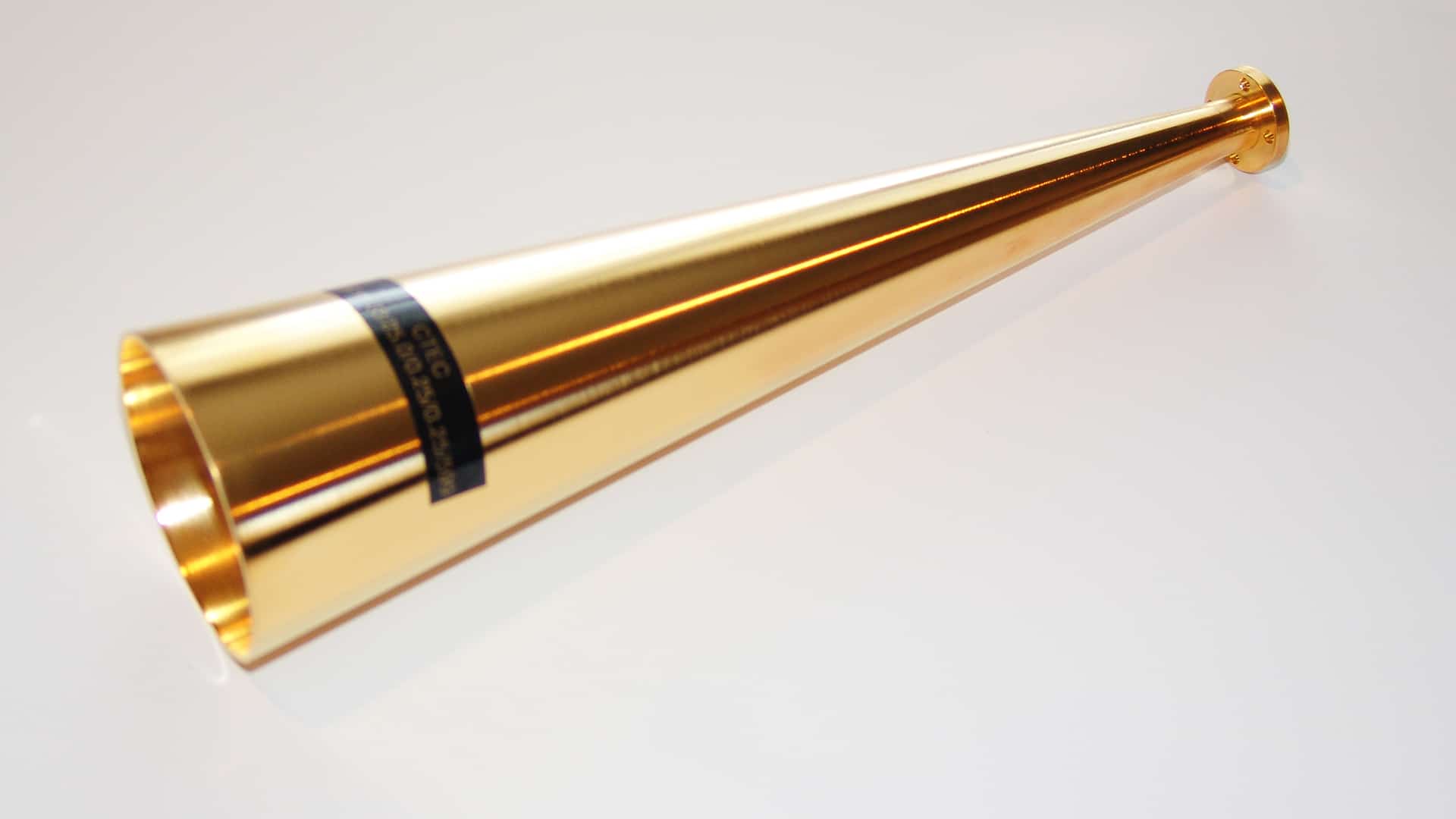
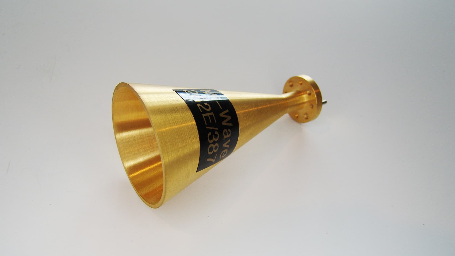
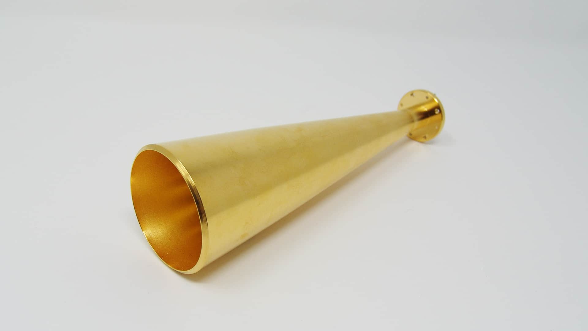
Mi-Wave’s Series 262 Conical Horn Antennas are precision-engineered, wideband antennas designed to deliver smooth radiation patterns, reliable directivity, and consistent performance across RF and microwave frequency ranges. Conical horn antennas are valued for their broadband impedance matching, stable beam shape, and low insertion loss, making them versatile solutions for a wide range of high-frequency applications.
The Series 262 design features a circular aperture horn with a conical flare that efficiently transitions electromagnetic energy from a waveguide into free space. This geometry provides stable gain, symmetrical radiation characteristics, and low VSWR across a wide operating band, reducing system complexity and minimizing the need for multiple narrowband antennas.
Series 262 conical horn antennas are well suited for communication links, radar systems, test and measurement environments, and research applications where predictable radiation patterns, repeatable performance, and broadband operation are essential.
Note: The conical horn antennas shown on this website represent only a portion of Mi-Wave’s manufacturing capabilities. Mi-Wave designs and builds a wide range of additional conical horn antenna configurations beyond those listed, including custom frequency ranges, waveguide interfaces, polarization options, and mechanical form factors. Consult with Mi-Wave to discuss your specific application requirements.

| Waveguide Band | Model No. | Gain (dBi) | Circular Waveguide Internal Diameter (.XXX in Model No.) in Inches | Frequency Range (GHz) | 3 dB Beamwidth E-Plane (Degrees °) | 3dB Beamwidth (degree) H-plane | Polarization | VSWR | Antenna Port | Material | LINK |
|---|---|---|---|---|---|---|---|---|---|---|---|
| X-band | 262X-10/.XXX/39 | 10 | .XXX=1.094 .XXX=.938 .XXX= .797 | 8.2-9.97 8.5-11.6 9.97-12.4 | 59.42 | 57.7 | Circular Polarized | 1.3:1 | Circular Waveguide with UG-39/U Flange | Aluminum/Brass | |
| X-band | 262X-15/.XXX/39 | 15 | .XXX=1.094 .XXX=.938 .XXX= .797 | 8.2-9.97 8.5-11.6 9.97-12.4 | 15.28 | 18.54 | Circular Polarized | 1.3:1 | Circular Waveguide with UG-39/U Flange | Aluminum/Brass | |
| Ku-Band | 262KU-10/.XXX/419 | 10 | XXX=.660 XXX=.550 | 12.4-14.6 14.6-18.0 | 47.67 | 50.04 | Circular Polarized | 1.3:1 | Circular Waveguide with UG-419/U Flange | Aluminum/Brass | |
| Ku-Band | 262Ku-15/.XXX/419 | 15 | XXX=.660 XXX=.550 | 12.4-14.6 14.6-18.0 | 28.25 | 32.96 | Circular Polarized | 1.3:1 | Circular Waveguide with UG-419/U Flange | Aluminum/Brass | |
| K-Band | 262K-10/.XXX/595 | 10 | XXX=.470 XXX .396 XXX=.328 | 18.0-20.5 20.4-24.5 24.5-26.5 | 45.72 | 48.54 | Circular Polarized | 1.3:1 | Circular Waveguide with UG-595/U Flange or UG-425/U Flange | Aluminum/Brass | |
| K-Band | 262K-15/.XXX/595 | 15 | XXX=.470 XXX .396 XXX=.328 | 18.0-20.5 20.4-24.5 24.5-26.5 | 26.5 | 31.13 | Circular Polarized | 1.3:1 | Circular Waveguide with UG-595/U Flange or UG-425/U Flange | Aluminum/Brass | |
| K-Band | 262K-20/.XXX/595 | 20 | XXX=.470 XXX .396 XXX=.328 | 18.0-20.5 20.4-24.5 24.5-26.5 | 14.48 | 17.61 | Circular Polarized | 1.3:1 | Circular Waveguide with UG-595/U Flange or UG-425/U Flange | Aluminum/Brass | |
| Ka-Band | 262A-10/.XXX/599 | 10 | XXX=.328 XXX=.281 XXX=.250 XXX= .219 | 26.5-28.5 28.5-33.0 33.0 -38.5 38.5-40.0 | 47.64 | 49.03 | Circular Polarized | 1.3:1 | Circular Waveguide with UG-599/U Flange or UG-381/U Flange | Aluminum/Brass | |
| Ka-Band | 262A-15/.XXX/599 | 15 | XXX=.328 XXX=.281 XXX=.250 XXX= .219 | 26.5-28.5 28.5-33.0 33.0 -38.5 38.5-40.0 | 23.44 | 27.94 | Circular Polarized | 1.3:1 | Circular Waveguide with UG-599/U Flange or UG-381/U | Aluminum/Brass | |
| Ka-Band | 262A-20/.XXX/599 | 20 | XXX=.328 XXX=.281 XXX=.250 XXX= .219 | 26.5-28.5 28.5-33.0 33.0 -38.5 38.5-40.0 | 15.9 | 19.39 | Circular Polarized | 1.3:1 | Circular Waveguide with UG-599/U Flange or UG-381/U | Aluminum/Brass | |
| Ka-Band | 262A-25/.XXX/599 | 25 | XXX=.328 XXX=.281 XXX=.250 XXX= .219 | 26.5-28.5 28.5-33.0 33.0 -38.5 38.5-40.0 | 8.62 | 10.55 | Circular Polarized | 1.3:1 | Circular Waveguide with UG-599/U Flange or UG-381/U | Aluminum/Brass | |
| B-Band | 262B-10/.XXX/383 | 10 | XXX=.250 XXX=.219 XXX=.188 | 33.0-38.5 38.5-43.0 43.0-50.0 | 49.92 | 51.66 | Circular Polarized | 1.3:1 | Circular Waveguide with UG-383/U Flange | Aluminum/Brass | |
| B-Band | 262B-15/.XXX/383 | 15 | XXX=.250 XXX=.219 XXX=.188 | 33.0-38.5 38.5-43.0 43.0-50.0 | 25.27 | 29.88 | Circular Polarized | 1.3:1 | Circular Waveguide with UG-383/U Flange | Aluminum/Brass | |
| B-Band | 263B-20/.XXX/383 | 20 | XXX=.250 XXX=.219 XXX=.188 | 33.0-38.5 38.5-43.0 43.0-50.0 | 14.36 | 17.56 | Circular Polarized | 1.3:1 | Circular Waveguide with UG-383/U Flange | Aluminum/Brass | |
| B-Band | 262B-25/.XXX/383 | 25 | XXX=.250 XXX=.219 XXX=.188 | 33.0-38.5 38.5-43.0 43.0-50.0 | 8.23 | 9.96 | Circular Polarized | 1.3:1 | Circular Waveguide with UG-383/U Flange | Aluminum/Brass | |
| U-Band | 262U-10/.XXX/383 | 10 | XXX=.219 XXX=.188 XXX=.165 XXX=.141 | 38.5-43.0 43.0-50.0 50.0-58.0 58.0-60.0 | 54.64 | 54.84 | Circular Polarized | 1.3:1 | Circular Waveguide with UG-383/U-M Flange | Aluminum/Brass | |
| U-Band | 262U-15/.XXX/383 | 15 | XXX=.219 XXX=.188 XXX=.165 XXX=.141 | 38.5-43.0 43.0-50.0 50.0-58.0 58.0-60.0 | 29.53 | 34.39 | Circular Polarized | 1.3:1 | Circular Waveguide with UG-383/U-M Flange | Aluminum/Brass | |
| U-Band | 262U-20/.XXX/383 | 20 | XXX=.219 XXX=.188 XXX=.165 XXX=.141 | 38.5-43.0 43.0-50.0 50.0-58.0 58.0-60.0 | 12.34 | 15.17 | Circular Polarized | 1.3:1 | Circular Waveguide with UG-383/U-M Flange | Aluminum/Brass | |
| U-Band | 262U-25/.XXX/383 | 25 | XXX=.219 XXX=.188 XXX=.165 XXX=.141 | 38.5-43.0 43.0-50.0 50.0-58.0 58.0-60.0 | 8.78 | 10.76 | Circular Polarized | 1.3:1 | Circular Waveguide with UG-383/U-M Flange | Aluminum/Brass | |
| V-Band | 262V-10/.XXX/385 | 10 | XXX=.165 XXX=.141 XXX=.125 | 50.0-58.0 58.0-68.0 68.0-75.0 | 55.99 | 55.68 | Circular Polarized | 1.3:1 | Circular Waveguide with UG-385/U Flange | Aluminum/Brass | |
| V-Band | 262V-15/.XXX/385 | 15 | XXX=.165 XXX=.141 XXX=.125 | 50.0-58.0 58.0-68.0 68.0-75.0 | 29.69 | 34.56 | Circular Polarized | 1.3:1 | Circular Waveguide with UG-385/U Flange | Aluminum/Brass | |
| V-Band | 262V-20/.XXX/385 | 20 | XXX=.165 XXX=.141 XXX=.125 | 50.0-58.0 58.0-68.0 68.0-75.0 | 15.22 | 18.64 | Circular Polarized | 1.3:1 | Circular Waveguide with UG-385/U Flange | Aluminum/Brass | |
| V-Band | 262V-25/.XXX/385 | 25 | XXX=.165 XXX=.141 XXX=.125 | 50.0-58.0 58.0-68.0 68.0-75.0 | 7.68 | 9.32 | Circular Polarized | 1.3:1 | Circular Waveguide with UG-385/U Flange | Aluminum/Brass | |
| E-Band | 262E-10/.XXX/387 | 10 | XXX=.141 XXX=.125 XXX=.110 XXX=.094 | 60.0-68.0 68.0-77.0 77.0-87.0 87.0-90.0 | 51.39 | 52.7 | Circular Polarized | 1.3:1 | Circular Waveguide with UG-387/U Flange | Aluminum/Brass | |
| E-Band | 262E-15/.XXX/387 | 15 | XXX=.141 XXX=.125 XXX=.110 XXX=.094 | 60.0-68.0 68.0-77.0 77.0-87.0 87.0-90.0 | 28.39 | 33.22 | Circular Polarized | 1.3:1 | Circular Waveguide with UG-387/U Flange | Aluminum/Brass | |
| E-Band | 262E-20/.XXX/387 | 20 | XXX=.141 XXX=.125 XXX=.110 XXX=.094 | 60.0-68.0 68.0-77.0 77.0-87.0 87.0-90.0 | 15.59 | 18.97 | Circular Polarized | 1.3:1 | Circular Waveguide with UG-387/U Flange | Aluminum/Brass | |
| E-Band | 262E-25/.XXX/387 | 25 | XXX=.141 XXX=.125 XXX=.110 XXX=.094 | 60.0-68.0 68.0-77.0 77.0-87.0 87.0-90.0 | 8 | 9.74 | Circular Polarized | 1.3:1 | Circular Waveguide with UG-387/U Flange | Aluminum/Brass | |
| W-Band | 262W-10/.XXX/387 | 10 | XXX=.125 XXX=.110 XXX=.094 XXX=.082 | 75.0-77.0 77.0-87.0 87.0-100.0 100.0-110.0 | 60.48 | 58.32 | Circular Polarized | 1.3:1 | Circular Waveguide with UG-387/U-M Flange | Aluminum/Brass | |
| W-Band | 262W-15/.XXX/387 | 15 | XXX=.125 XXX=.110 XXX=.094 XXX=.082 | 75.0-77.0 77.0-87.0 87.0-100.0 100.0-110.0 | 29.86 | 34.73 | Circular Polarized | 1.3:1 | Circular Waveguide with UG-387/U-M Flange | Aluminum/Brass | |
| W-Band | 262W-20/.XXX/387 | 20 | XXX=.125 XXX=.110 XXX=.094 XXX=.082 | 75.0-77.0 77.0-87.0 87.0-100.0 100.0-110.0 | 16.33 | 19.96 | Circular Polarized | 1.3:1 | Circular Waveguide with UG-387/U-M Flange | Aluminum/Brass | |
| W-Band | 262W-25/.XXX/387 | 25 | XXX=.125 XXX=.110 XXX=.094 XXX=.082 | 75.0-77.0 77.0-87.0 87.0-100.0 100.0-110.0 | 9.32 | 11.37 | Circular Polarized | 1.3:1 | Circular Waveguide with UG-387/U-M Flange | Aluminum/Brass | |
| F-Band | 262F-10/.XXX/387 | 10 | XXX=.094 XXX=.082 XXX=.075 XXX=.067 | 87.0-100.0 100.0-112.0 112.0-125.0 125.0-140.0 | 55.75 | 55.54 | Circular Polarized | 1.3:1 | Circular Waveguide with UG-387/U-M Flange | Aluminum/Brass | |
| F-Band | 262F-15/.XXX/387 | 15 | XXX=.094 XXX=.082 XXX=.075 XXX=.067 | 87.0-100.0 100.0-112.0 112.0-125.0 125.0-140.0 | 30.81 | 35.41 | Circular Polarized | 1.3:1 | Circular Waveguide with UG-387/U-M Flange | Aluminum/Brass | |
| F-Band | 262F-20/.XXX/387 | 20 | XXX=.094 XXX=.082 XXX=.075 XXX=.067 | 87.0-100.0 100.0-112.0 112.0-125.0 125.0-140.0 | 14.54 | 17.87 | Circular Polarized | 1.3:1 | Circular Waveguide with UG-387/U-M Flange | Aluminum/Brass | |
| F-Band | 262F-25/.XXX/387 | 25 | XXX=.094 XXX=.082 XXX=.075 XXX=.067 | 87.0-100.0 100.0-112.0 112.0-125.0 125.0-140.0 | 9.25 | 11.48 | Circular Polarized | 1.3:1 | Circular Waveguide with UG-387/U-M Flange | Aluminum/Brass | |
| D-Band | 262D-10/.XXX/387 | 10 | XXX=.082 XXX=.075 XXX=.067 XXX=.059 | 100.0-112.0 112.0-125.0 125.0-140.0 140.0-170.0 | 55.75 | 55.54 | Circular Polarized | 1.3:1 | Circular Waveguide with UG-387/U-M Flange | Aluminum/Brass | |
| D-Band | 262D-15/.XXX/387 | 15 | XXX=.082 XXX=.075 XXX=.067 XXX=.059 | 100.0-112.0 112.0-125.0 125.0-140.0 140.0-170.0 | 30.81 | 35.41 | Circular Polarized | 1.3:1 | Circular Waveguide with UG-387/U-M Flange | Aluminum/Brass | |
| D-Band | 262D-20/.XXX/387 | 20 | XXX=.082 XXX=.075 XXX=.067 XXX=.059 | 100.0-112.0 112.0-125.0 125.0-140.0 140.0-170.0 | 16.29 | 19.9 | Circular Polarized | 1.3:1 | Circular Waveguide with UG-387/U-M Flange | Aluminum/Brass | |
| D-Band | 262D-25/.XXX/387 | 25 | XXX=.082 XXX=.075 XXX=.067 XXX=.059 | 100.0-112.0 112.0-125.0 125.0-140.0 140.0-170.0 | 9.25 | 11.48 | Circular Polarized | 1.3:1 | Circular Waveguide with UG-387/U-M Flange | Aluminum/Brass | |
| G-Band | 262G-10/.XXX/387 | 10 | XXX=.059 | 140.0-170.0 | 53.09 | 53.85 | Circular Polarized | 1.3:1 | Circular Waveguide with UG-387/U-M Flange | Aluminum/Brass | |
| G-Band | 262G-15/.XXX/387 | 15 | XXX=.059 | 140.0-170.0 | 29.71 | 34.61 | Circular Polarized | 1.3:1 | Circular Waveguide with UG-387/U-M Flange | Aluminum/Brass | |
| G-Band | 262G-20/.XXX/387 | 20 | XXX=.059 | 140.0-170.0 | 16.57 | 20.26 | Circular Polarized | 1.3:1 | Circular Waveguide with UG-387/U-M Flange | Aluminum/Brass | |
| G-Band | 262G-25/.XXX/387 | 25 | XXX=.059 | 140.0-170.0 | 8.3 | 10.17 | Circular Polarized | 1.3:1 | Circular Waveguide with UG-387/U-M Flange | Aluminum/Brass | |
| H-Band | 262H-25/.XXX/387 | 25 | XXX=.049 | 170.0-325.0 | 8.31 | 10.2 | Circular Polarized | 1.3:1 | Circular Waveguide with UG-387/U-M Flange | Aluminum/Brass | |
| J-Band | 262J-25/.XXX/387 | 25 | XXX=.049 | 170.0-325.0 | 9.2 | 11.42 | Circular Polarized | 1.3:1 | Circular Waveguide with UG-387/U-M Flange | Aluminum/Brass |
Conical Horn Antennas
Mi-Wave designs and manufactures high-performance conical horn antennas engineered for reliable operation across RF, microwave, and millimeter-wave frequency ranges. With decades of experience in high-frequency RF hardware, Mi-Wave delivers conical horn antennas built to meet demanding requirements for electrical performance, mechanical stability, and repeatability.
Conical horn waveguide antennas are widely used for their broadband impedance matching, strong directivity, low insertion loss, and stable radiation characteristics across wide frequency ranges. Mi-Wave conical horn antennas are designed to maintain consistent gain and predictable beam shape across the operating band, making them well suited for communications, radar, and test and measurement applications.
Conical horn antennas are part of Mi-Wave’s broader portfolio of RF products and components supplied to customers worldwide, supporting both laboratory-based testing and field-deployed systems.
Features
-
Low VSWR across the operating frequency band, ensuring efficient power transfer, minimal signal reflection, and improved overall system performance
-
Wide bandwidth capability, allowing a single conical horn antenna to support multiple frequencies without retuning or replacement
-
Smooth, well-controlled beamwidths, providing reliable directivity, consistent coverage, and reduced susceptibility to off-axis interference
-
Polarization-insensitive performance, enabling flexible system integration and stable operation across varying polarization conditions
-
High power handling capability, suitable for demanding transmit and receive applications
-
Low insertion loss and stable electrical characteristics, supporting accurate measurements and reliable long-term operation
-
Precision mechanical construction, ensuring repeatable performance in both laboratory and field environments
-
Compatibility with standard waveguide interfaces, allowing easy integration into existing RF, microwave, and millimeter-wave systems
Applications
-
Radar and Telemetry Systems
Used in radar, tracking, and telemetry applications where consistent beam shape, stable gain, and reliable signal transmission are required. -
Point-to-Point Communication Systems
Ideal for line-of-sight RF, microwave, and millimeter-wave communication links that require strong directivity, high link margins, and minimal interference. -
Test and Measurement Environments
Commonly used for antenna characterization, gain measurements, system calibration, and performance validation in laboratory and field test setups. -
RF, Microwave, and Millimeter-Wave Communication Links
Supports broadband signal transmission and reception across a wide range of operating frequencies. -
Research and Development Platforms
Suitable for R&D applications requiring broadband performance, predictable radiation patterns, and repeatable results.
Why Choose Mi-Wave for SatCom
Mi-Wave is a trusted manufacturer of RF, microwave, and millimeter-wave antennas and components supporting satellite communications (SatCom) systems worldwide. Our conical horn antennas are engineered to deliver wideband performance, stable radiation patterns, and reliable electrical characteristics required for satellite uplink, downlink, and ground station applications.
High-Frequency SatCom Engineering Expertise
With decades of experience in microwave and millimeter-wave design, Mi-Wave develops conical horn antennas optimized for low VSWR, controlled beamwidth, and consistent gain across satellite communication bands, ensuring reliable link performance and predictable system behavior.
Precision Manufacturing and Quality Control
Each antenna is manufactured using precision machining and controlled assembly processes to ensure repeatable electrical performance, mechanical stability, and long-term reliability in continuous-duty SatCom environments, including gateway and ground station deployments.
Broad SatCom Frequency and Application Support
Mi-Wave supports conical horn antennas across a wide range of satellite communication frequency bands, including X-, Ku-, Ka-, Q-, V-, and W-Band, making them suitable for satellite gateways, feeder links, point-to-point SatCom links, and system validation environments.
Custom SatCom Antenna Solutions
In addition to standard offerings, Mi-Wave provides custom conical horn antenna designs tailored to specific SatCom frequency plans, bandwidth requirements, polarization schemes, waveguide interfaces, and mechanical constraints. Our sales engineering team works closely with customers to ensure seamless integration into satellite ground and gateway systems.
What Conical Horn Antennas Are and What They Do in SatCom Systems
Conical horn antennas are directional, broadband antennas used in satellite communications (SatCom) systems to efficiently transition electromagnetic energy from a rectangular or circular waveguide into free space. The circular, cone-shaped flare produces rotationally symmetric radiation patterns, providing stable impedance matching, predictable beam characteristics, and consistent polarization behavior across satellite frequency bands.
In SatCom ground stations and gateway systems, conical horn antennas are commonly used where wide bandwidth, stable gain, and repeatable radiation patterns are required. Their robust and straightforward design makes them a reliable solution for both fixed satellite gateways and transportable ground station platforms.
How Conical Horn Antennas Work in SatCom Applications
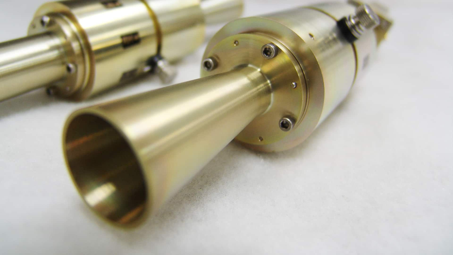
In SatCom systems, RF energy enters the conical horn antenna through a standard WR waveguide interface connected to the uplink or downlink RF chain. As the signal propagates through the gradually expanding conical flare, the electromagnetic fields are smoothly converted from guided wave propagation into free-space radiation.
This controlled transition delivers several performance advantages critical to satellite communications:
-
Low VSWR, improving power transfer and uplink efficiency
-
Stable beamwidth and consistent gain, supporting reliable satellite links
-
Smooth, symmetrical radiation patterns, reducing pointing and alignment sensitivity
-
Minimal pattern distortion across wide operating bandwidths
The circular symmetry of conical horn antennas ensures uniform E-plane and H-plane radiation patterns, which is especially important for gateway antenna alignment, system commissioning, and long-term operational stability.
SatCom Frequency Coverage and WR Waveguide Interfaces
Mi-Wave Series 262 conical horn antennas support operation across key microwave and millimeter-wave satellite communication bands, depending on configuration. Typical SatCom coverage spans from 8.2 GHz through 110 GHz, with custom frequency ranges available to support evolving satellite architectures.
Supported WR waveguide interfaces include:
-
WR-90 | 8.2–12.4 GHz | X-Band
-
WR-62 | 12.4–18.0 GHz | Ku-Band
-
WR-42 | 18.0–26.5 GHz | K-Band
-
WR-28 | 26.5–40.0 GHz | Ka-Band
-
WR-22 | 33.0–50.0 GHz | Q-Band
-
WR-15 | 50.0–75.0 GHz | V-Band
-
WR-10 | 75.0–110.0 GHz | W-Band
This wide compatibility allows conical horn antennas to integrate seamlessly into SatCom RF chains, including high-power amplifiers (HPAs), low-noise amplifiers (LNAs), upconverters, downconverters, and monitoring equipment used in satellite ground stations and gateways.
What Conical Horn Antennas Do in SatCom Systems
In satellite communication systems, conical horn antennas are used to transmit and receive satellite uplink and downlink signals with controlled directivity and broadband performance. They provide a balance between wide frequency coverage and directional gain, supporting:
-
Satellite gateway and ground station operations
-
Point-to-point satellite communication links
-
Feeder link and backhaul systems
-
Antenna pattern verification and system alignment
-
SatCom test, measurement, and validation environments
Their predictable radiation behavior makes them suitable as reference antennas and verification tools during gateway deployment and system maintenance.
Why Conical Horn Antennas Matter in Satellite Communications
The controlled flare geometry and symmetrical radiation characteristics of conical horn antennas provide several advantages essential to SatCom performance:
-
Low VSWR across wide bandwidths, maximizing link margin and system efficiency
-
Stable polarization characteristics, minimizing polarization mismatch losses
-
Consistent gain and beamwidth, supporting reliable uplink and downlink performance
-
Low pattern distortion and controlled sidelobes, reducing interference and spillover
These characteristics make conical horn antennas a dependable solution for satellite gateways, feeder links, ground station systems, and SatCom test and validation environments.